Leaky Coaxial Cable based Generalized Pinching-Antenna Systems with Dual-Port Feeding
By leveraging the distributed leakage radiation of leaky coaxial cables (LCXs), the concept of pinching antennas can be generalized from the conventional high-frequency waveguide based architectures to cable based structures in lower-frequency scenar…
Authors: Kaidi Wang, Zhiguo Ding, Daniel K. C. So
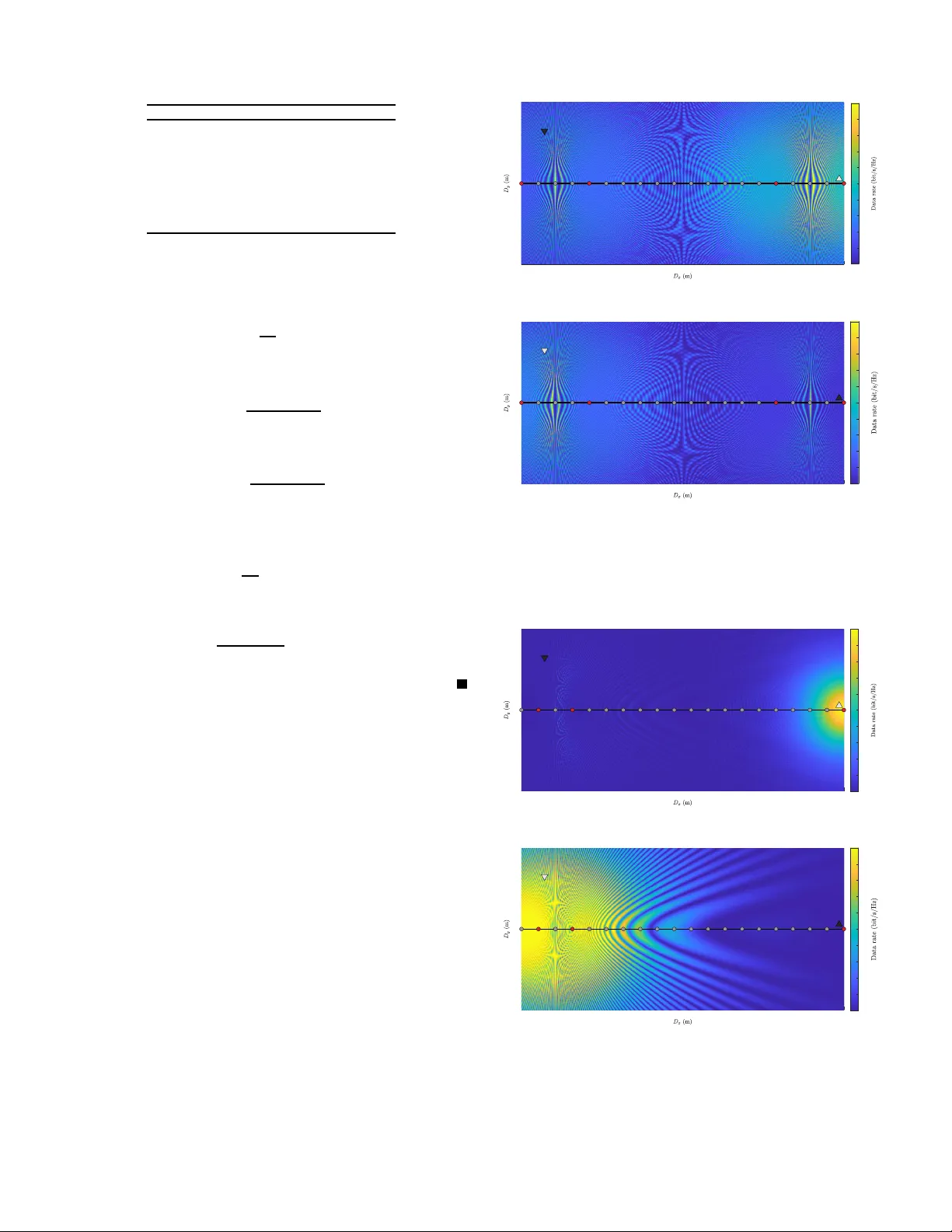
1 Leak y Coaxial Cable based Generalized Pinching-Antenna Systems with Dual-Port Feeding Kaidi W ang, Membe r , IEEE, Zhiguo Ding, F ellow , IEEE, and Dan iel K. C. So , Senior Memb e r , IEEE Abstract —By lev eraging the distributed leakage radiation of leaky coaxial cabl es (LCXs), the concept of pinching antennas can be g eneralized fro m the c onv entional high-frequency wa veguide based a rchitectures to cable based structures in lower -fr equency scenarios. This paper inv estigates an LCX based generalized pinchin g-anten na sy stem with du al-p ort feeding. By enabling bidirectional excitation along each ca ble, the p roposed d esign significantly enhances spatial d egrees of freedom. A compre- hensive chann el model is d ev eloped to characterize intra-cable attenuation, bidirectional phase progression, sl ot based radiation , and wireless pro pagation. Based on this model, both analog and hybrid beamforming framewor ks are stu died with the objectiv e of maximizing the min imum achieva ble data rate. For analog transmission, slot activ ation, port selection, and power allocation are jointly optimized u sing matching theory , coalitional games, and b isection based power control. For hybrid transmission, zero- fo rcing (ZF ) d igital precoding is incorporated to eliminate int er - user interference, thereby simplifying slot activation and enablin g closed-fo rm optimal power allocation. Simu lation results demon- strate that d ual-port feedin g p ro vides n otable performa nce gains ov er single-port LCX systems an d fixed-antenna benchmarks, validating the effective ness of th e proposed beamforming and resour ce allocation designs under various transmit power lev els and cable para meters. Index T erms —Generalized pinching-anten na systems, leaky coaxial cable (L CX), dual-port feeding, port selection, slot ac- tiva tion, r esource allocation I . I N T R O D U C T I O N The r a p id ev olution o f wireless co mmunicatio n n etworks has driven a co ntinuou s increase in de m and f or flexible and reconfigu rable antenn a tec h nologies, p articularly in co mplex propag ation en viro nments such as in door scenarios, transp orta- tion systems, and ind ustrial deploymen ts. T o adap t wireless channels to dy namic environments, a variety of flexible an- tenna parad igms have b een extensiv ely in vestigated, including reconfigu rable intelligen t surfaces (RISs), fluid antennas, and movable antennas [1]–[ 3]. RISs reconfigu re wireless chan - nels b y ad justing the electromag netic responses of passive reflecting elem ents, th ereby r e shaping the compo site prop- agation paths between transmitters and r eceiv ers [4]. Fluid antennas exploit conductive fluids to dynamically reco nfigure antenna p ositions within a constrain e d p hysical space [5], while m ovable antenn as enable spatial adaptatio n th rough mechanical displacemen t of rad iating elemen ts [6] . Th ese Kaidi W ang and Daniel K. C. So are with the Department of E lectrical and Electroni c E nginee ring, the Uni versity of Mancheste r, Manchest er , M1 9BB, UK (email: kaidi.wa ng@ieee.or g; d.so@manchester . ac.uk). Zhiguo Ding is with the School of Electrical and Electronic Engineer - ing (EEE), Nanyang T echno logical Univ ersity , Singapore 639798 (e-mail: zhiguo.din g@ntu.edu.sg). technolog ies h a ve dem onstrated significan t po tential in im- proving link reliability and spectral efficiency thr ough pr e cise channel ada p tation. Howe ver , such reconfigur ation is gener ally realized throu gh ind irect channel manip ulation via cascaded transmitter-surface-receiver link s or wa velength- scale element displacement, wh ich limits direct co ntrol over th e ph ysical radiation lo cation an d large-scale p r opagation geometr y . T o meet th e need for large-scale spatial reconfigu rability , the con cept of pinching an tennas has recently em erged as a promising solution [7 ]. By attaching controllable perturb ation elements, comm only re f erred to as pin c hes, onto a gu ided- wa ve structur e, the electr omagnetic energy p ropagatin g along the med ium can be in tentionally leaked at selected locatio n s [8]. As a result, th e radiation position beco mes d ynamically reconfigu rable over distances far e xceed ing the carrier wa ve- length, enabling substan tial mo dification of wireless ch annel condition s [9], [10]. Such a mechanism allows pinchin g an- tennas to reshap e spatial radiation pattern s, improve coverage perfor mance, and ev en establish line - of-sight (Lo S) link s in scenarios with severe blo ckage [1 1], [1 2]. Comp ared with conv ention al flexible an tenna technolo g ies, p inching antennas provide a f undame n tally different re c onfiguratio n paradigm by directly manipu lating gu ided-wave propa g ation, while re ta in - ing attractive featu res such as low hardware cost, minimal reliance on active rad io -frequ ency (RF) com ponents, an d high implementatio n flexibility [13]. A. Related W orks Building upon the fund amental con c ept of pinch ing anten- nas, extensive research e fforts h av e been dev oted to extend- ing system mo dels an d enhancin g com munication capab ili- ties. From an implementa tio n perspective, a p r actical m ulti- wa veguide pinch ing-anten na system was prop osed by intro- ducing pre- installed p inching a n tennas at d iscrete candidate locations, thereby transfor ming the conventional co ntinuous antenna placement pr oblem into a discrete antenna acti vation and resource allocatio n f r amew ork [1 4]. Beyond mo deling realism, several studies have further explor ed wave guide mor- pholog y as an impo rtant design dim ension to enh ance d eploy- ment flexibility and transmission per formanc e [ 15], [16] . I n this co ntext, a segmented wa veguide enabled pinching -antenna system was prop osed to en able phy sically co nsistent u plink commun ications by elimin ating in te r-antenn a re-radiation ef - fects, while simultaneou sly mitigating in-wave gu id e attenu a - tion and improvin g sy stem maintainability throug h m odular wa veguide deploymen t [1 5]. In contrast, a two-d imensional pinching -antenna architectu re was p roposed to extend the 2 conv ention al line sh aped wave guid e to for m planar co nfigura- tions, thereby enabling re c o nfigurab le ap ertures for en hanced spatial beamformin g capability [16]. At the sy stem par a digm lev el, en viro nment division mu ltiple access (EDMA) was introdu c ed as a novel multiple-a c cess framew ork ena b led by the c ontrollable establishment and blo ckage of LoS lin ks using pinching an tennas, wh ich facilitates spatial user separation an d interferen ce supp r ession beyon d conventional beam dom ain multiplexing [17] . From the sign al doma in transmission p erspective, enhanced transmission architectures have a lso been in vestigated. Specif- ically , a fully conn ected tri- h ybrid beamf orming design em- ployed a tunab le phase shifter n e twork to inter c onnect all radio frequency c h ains with all w ave guid es, thereby en abling joint dig ital, analog, an d pinch ing b eamform ing with increased spatial degrees of freedom [18 ]. In addition , a multi-mo de pinching -antenna system exploited a wa veguide supportin g the simultaneou s propaga tion of multiple guided modes, e n abling mode d omain m ultiplexing for multi-user commun ications [19]. Meanwhile, th e f eeding architectur e of pinching- antenna systems has attracted growing atten tion, as it fund amentally determines the excitation man ner and pr opagation cha r acter- istics of the guide d wa ves. A wireless fed pinchin g-antenn a system was p roposed to relax wired dep loyment co nstraints and imp rove installation flexibility [2 0], while a center-fed pinching -antenna arch itecture enab led bidirection al guid ed- wa ve pro pagation within a single wav eguide throu gh control- lable power splitting, thereb y do ubling the av ailable spatial degrees of f r eedom com pared to conventional end -fed c o nfig- urations [21]. B. Motivatio n and Contrib utions Despite the extensive sy stem level advancements achiev ed in p inching-a ntenna research, existing studies have pred om- inantly focu sed on dielectric wav eguide based imp lementa- tions, which in herently restrict o peration to hig h-frequ ency bands and limit app licability in sub-6 GHz wireless scena r ios. Motiv ated by this limitation, the extension of th e pin ching- antenna paradig m to more genera l guidin g structu res has been explored, where leaky coax ia l ca b les (LCXs) were identified as a poten tial p hysical platform [22]. In [23], an LCX based generalized pinch ing-anten na fram ework was developed v ia slot activation, illustrating the feasibility of flexible and large- scale antenna reconfigu r ation beyond wa veguide based struc- tures. Follo wing th is d irection, th is work incorpo rates dual- port fe e ding into LCX b ased g eneralized pinch ing-anten na architecture s with slot activ ated radiation . Although du al-port excitation is common in conventional LCX systems [24] , [25], its integration with dynam ic slot activ ation introduce s distinct cha n nel character istics an d beamfor ming ch allenges due to b idirectional gu ided-wave pro pagation an d controllab le radiation patterns. By exploiting the resulting additiona l spa- tial degrees of fr eedom, this work develops tailore d channel models and beam f orming designs, demonstra tin g significant perfor mance gains. The main contributions of this p aper a r e summarized as follows. • A du al-port f ed LCX based gen e r alized p inching- antenna system is pr oposed, where bidirectio nal excitation fund a- mentally ch anges the guided-wave p ropagatio n and rad ia- tion charac te r istics. K ey insights into the resulting channel structure and interferen ce be h avior are r e vealed, which serve as the basis for the subsequent design of analog and hybr id transmission schemes. A correspo nding channel mo del is established to capture the c o mposite effects o f b idirectional guided tr ansmission an d wireless radiation. • Based on the developed dual-po rt LCX chan nel mod el, two max-min optimization p roblems a re f o rmulated to m aximize the minimu m achievable data rate u n der the analog and hybrid transmission schemes, respectively . For the a n alog scheme, slot activ ation, port selection, and p ower allocation are jointly considered, whereas for the hybrid sch e m e, slot activ ation an d power allo cation ar e o ptimized un der d ig ital precod in g to ensure user fairness. • For the an a lo g transmission schem e, an efficient solu tion framework is developed to solve the resulting mixed-integer optimization pro blem thr ough pr oblem d ecomposition . Port selection is fo r mulated a s a perfect matchin g, within wh ich slot activ ation is updated via a coalitional game, while power allocation is o ptimized u sin g a bisection based ap proach , enabling low-comp lexity analog transmission design under bidirection al LCX excitation . • For the h ybrid transmission scheme, ze r o-forc in g (ZF) beamfor ming is inco rporated into the analog design to suppress inter-user inter f erence. As a resu lt, all activ ated slots can be treated as a single coalition in the co rrespon d ing coalitional game fo rmulation . The resulting inter ference-f ree transmission structure enables a clo sed -form solutio n for power allo cation, leading to an efficient hy brid beamfor m ing design under bidirection al LCX excitation . • Simulation results are p r esented to validate th e prop osed dual-po rt fed LCX b a sed gen e r alized pinch in g-antenn a ar - chitecture an d the effecti veness of the developed analog an d hybrid tran smission sche m es. The results d emonstrate th e advantages of dua l-port feeding and confir m th at the pro- posed solutions sign ificantly improve the min imum achiev- able rate comp ared with conventional single-po rt LCX con- figuration s and fixed-anten na benc hmark systems. I I . S Y S T E M M O D E L Consider an LCX based gen eralized pinching-anten na sy s- tem, as sh own in Fig. 1, consisting of K para llel cables, each equippe d with M r a diation slots, serving a total o f N users, where N = 2 K . All cables are installed at a un iform height d and are or iented along the x -ax is. Th e sets of ca b les an d users are den oted b y K = { 1 , 2 , . . . , K } and N = { 1 , 2 , . . . , N } , respectively , an d the slo t index set f or cable k is giv en by M k = { 1 , 2 , . . . , M } . I n the considered system, users ar e random ly d istributed within a rectangu la r service region of dimensions D x × D y , centered at (0 , 0 , 0 ) . The location of user n is den oted by ψ n = ( x n , y n , 0) . Th e k -th cable is located at y = y k , and the position of th e m -th slot on cab le k is given by ψ slot k,m = ( x m , y k , d ) , where adjacent slots are unifor m ly sp a ced such that x m +1 − x m = ∆ d . 3 Fig. 1: An illustration of the pr oposed LCX based generalized pinching -antenna system op erating in dual-port mod e. A. Chan n el Model As shown in Fig. 1, the dual-por t ope rating mode is considered , in which each c able is excited f r om both end s, referred to as ports L an d R [24] , [26 ]. Owing to th e d ifferent propag ation distan c es a lo ng the cable, the sig nals injected from the two po rts experience distinct attenu ation and pha se variations 1 [27]. For cab le k , the intra-cable chann el between port L , located at the left end of th e c able, an d the m -th slot is expre ssed as h L k,m = 10 − κ r 20 ( m − 1)∆ d e − j 2 π λ √ ε r ( m − 1)∆ d , (1) where κ r is the attenu ation constant of the co axial cab le in decibels per meter , λ is the free-space wa velength, and ε r is the relative permittivity of the dielectr ic ma terial. Similarly , for port R lo cated at the r ight end o f the cab le, the pr opagation distance to the m -th slot is ( M − m )∆ d , and the correspo n ding intra-cable ch annel is giv en by h R k,m = 10 − κ r 20 ( M − m )∆ d e − j 2 π λ √ ε r ( M − m )∆ d . (2) Based on the above intra-ca b le channel model, the following remark provides insight into th e attenuation redu ction achieved by d ual-por t f eeding. Remark 1. Compared with single- port feeding, dual-p ort feeding can sub stantially reduce the intra-cable atten uation. Under single- port op e ration, the ma ximum pr opagation dis- tance occurs at the farthest slot and equals ( M − 1)∆ d . In contrast, with dual-p ort feeding, ea ch slot is effectively served by its nea r est p ort, such tha t the maximum pr opaga tion distance is reduced to at mo st M − 1 2 ∆ d . As a r esult, the worst-case intra-ca b le atten uation, expr essed in decibels, is appr oximately ha lved. In ad dition to enh ancing the d esired sign al strength , dua l- port feeding can also facilitate multi-user inter ference mitiga- tion, a s summarized in the fo llowing r e mark. 1 T o enable dual-port ex citation in practi ce, both ports c an be dri ven by a single base station via external feeder cables. Since these feeder cables are low-loss transmission lines, the associat ed loss is typical ly negl igible compared with the longitudi nal attenuati on of the LCX and is therefore omitted from the channel model. Remark 2. When the desired sign a l for each u ser is injected thr ough a sing le selected po rt, the signa ls intended for other users fr om an o ther port typically pr opagate over a longer distance along th e ca ble b e for e bein g radiated to war d a g iven user . Consequently , these interfering compo n ents e xperien c e str onger intra-cable attenuation , which effectively r educes the interfer ence p ower o bserved at the users. In th e co nsidered system, each c oaxial cab le is installed with the r a d iation slots oriented downward. As a result, each slot b e h av es as a magnetic dip ole radia to r and directs electro - magnetic radiation tow ards the u ser plan e beneath the c able. As repor ted in [2 8], the downward radiation pattern of each slot follows Lamber t’ s cosine law . When exp r essed in terms o f the elevation angle, this Lambertian chara cteristic introd uces a sin( θ ) factor , which captures the ang u lar dep e ndence of th e radiated en e rgy towards the user plane [ 29]. Accordin gly , the LoS co mponen t of the channel b e tween slot m on ca b le k and user n is gi ven by h LoS k,m,n = η e − j 2 π λ k ψ n − ψ slot k,m k ψ n − ψ slot k,m sin( θ k,m,n ) , (3) where η = c 4 π f c is the fre e -space path-loss con stan t, with c den o ting the speed of light and f c the carr ier freque n cy , k ψ n − ψ slot k,m k is the Euclidea n distance between slot m o n cable k an d user n , and θ k,m,n is th e elev ation angle from slot m on ca b le k to u ser n . Specifically , due to the vertical separation d between the slot and the user plane, as shown in Fig. 1, the elevation an gle satisfies sin( θ k,m,n ) = d ψ n − ψ slot k,m . (4) T o mod el the non-lin e-of-sigh t (N L oS) componen t, L scat- tering p o ints are intro d uced. The resulting cha n nel between slot m on ca b le k an d user n is expressed as f ollows: h NLoS k,m,n = η L X ℓ =1 δ ℓ e − j 2 π λ ( k ψ scat ℓ − ψ slot k,m k + k ψ n − ψ scat ℓ k ) ψ scat ℓ − ψ slot k,m ψ n − ψ scat ℓ sin( θ k,m,ℓ ) , (5) where δ ℓ ∼ C N (0 , 1) is the comp lex gain associated with the propag ation p ath v ia scatter er ℓ , ψ scat ℓ = ( x ℓ , y ℓ , z ℓ ) is the location of scatterer ℓ , k ψ scat ℓ − ψ slot k,m k and k ψ n − ψ scat ℓ k a re the distances from slot m on cable k to scatterer ℓ and from scatterer ℓ to user n , respecti vely , and θ k,m,ℓ is the ele vation angle f rom slot m on cable k to scatterer ℓ . The overall channel f rom feed p ort X ∈ { L , R } to user n via slot m on cable k is gi ven by h X k,m,n = h X k,m h LoS k,m,n + h NLoS k,m,n . (6) According ly , the channel vecto r from the f eed po r t of cable k to user n c a n be presented as follows: h X k,n = h X k, 1 ,n , h X k, 2 ,n , . . . , h X k,M ,n T . (7) B. Ana log Beamforming via Slot Ac tivation Since the signals tran smitted f rom different feed p orts a lo ng the same cable e xper ience distinct phase variations, eac h slot 4 can radiate signals with identical amp litudes but different phases. By selectively activ ating or deactivating these slots 2 , pinching b ased an alog beamfo rming can thus be realized throug h binar y radiation contr ol. This mechanism fo llows the concept of pinching be a m forming introd u ced in [3 1], [32], in which spatial beam shaping is achieved without explicit ph ase shifters. Th e slot acti vation vector of cable k is defined as α k = [ α k, 1 , α k, 2 , . . . , α k,M ] T , (8) where α k,m is the a c ti vation indicator of slot m on cab le k , with α k,m = 1 in dicating that the slot is activ ated and α k,m = 0 otherwise. Accordin gly , the effecti ve channel from f e ed po rt X ∈ { L , R } on cable k to user n is giv en by h X k,n = 1 √ N k α T k h X k,n = 1 √ N k M X m =1 α k,m h X k,m,n , (9) where N k = P M m =1 α k,m is the num ber of acti vated slots on cable k . In th e co n sidered system, all slots exhibit identical radiation cha racteristics. The signal launched f rom a given feed por t is equally distributed in power across the activ ated slots, which lead s to the normalizatio n factor 1 / √ N k to r eflect the equal power sp lit of the injected port signal over th e N k activ ated slots. Nevertheless, the radiated power contributed b y each activated slot is g enerally unequ al d ue to the distance- depend ent in tra-cable attenu ation. The phy sical interpr etation o f the slot activ ation vector in the pr oposed L CX based arch itecture is summarized in the following remark. Remark 3. In the LCX b ased pin ching-anten na system, the slot activation vector serves as a n analog bea mformer . Activat- ing a slo t en a bles a po rtion of the guide d wave to radiate into fr ee space, with the radiated signal inheriting its a mplitude and phase fr om th e in tra-cable pr opagation . Acc or dingly , the contribution of e a ch slot d epends on its relative p osition to the users and the associated amplitud e attenu a tion and ph ase variations along the cable and th e wir eless channel. Since the signals transmitted fro m po rts L an d R experience different phase variations alon g the cable, coh erent comb ining across th e two p o rts is n ot fe asible unde r slot activ ation. In this case, the desired signal of each user is transmitted throug h only one selected por t on a single cable. The r efore, the tr a nsmit signal fr om p o rt X ∈ { L , R } of cable k is given by x X k = N X n =1 β X k,n p P t p n s n , (10) where β X k,n is th e port selection in d icator, P t is the total av ailable transmit p ower , p n is the power allocation coefficient for user n , and s n is the desired inform ation sym bol of user n . In particular, β X k,n = 1 indicates that th e sign al in tended for user n is transmitted through port X of cable k , whereas β X k,n = 0 o therwise. Moreover , the tran smitted symbols satisfy E | s n | 2 = 1 , ∀ n ∈ N . 2 Slot acti v ation and deacti va tion can be implemente d through va rious LCX reconfigura tion mechanisms, such as the applic ation of remov able conduct iv e or absorbing cov erings, or mechanical ly reconfigura ble outer conductors and layers that locall y exp ose or s hield radiatio n slots [30]. At user n , the signa ls transmitted fro m all feed p orts can be rec e i ved, as follows: y A n = K X k =1 h L k,n x L k + h R k,n x R k + n 0 (11) = K X k =1 r P t N k N X i =1 β L k,i α T k h L k,n + β R k,i α T k h R k,n √ p i s i + n 0 , where n 0 ∼ C N (0 , σ 2 ) is the add iti ve white Gaussian no ise (A WGN), an d σ 2 is the correspo n ding n oise po wer . Since each user is served by only one selected por t a n d coheren t c ombining acro ss different cables or feed ports is not co n sidered, the desired signal a n d interf erence powers are ev aluated as the sum of the corr esponding per-link received powers. A c cording ly , the received signa l- to-interfer ence-plus- noise ra tio (SINR) at user n is g iv en by γ A n = p n P K k =1 P t N k P X ∈{ L , R } β X k,n α T k h X k,n 2 P N i =1 ,i 6 = n p i P K k =1 P t N k P X ∈{ L , R } β X k,i α T k h X k,n 2 + σ 2 . (12) The co rrespond ing ach ie vable data r ate o f user n is R A n = log 2 1 + γ A n . (13) C. Hybrid Beamforming with Digital Pr ecod in g In the p roposed LCX b ased generalized pin ching-an tenna system, the two feed ports on each cable can be r egarded a s indepen d ent RF chains. With K cables d eployed, the downlink transmission can the r efore be mode le d as a multiple-inpu t single-outp ut (MISO) system with 2 K RF ch ains, in which the inform a tion sign als o f all user s are jointly precod ed at baseband and simultaneou sly transmitted throug h all feed ports on all cables. For user n , the corre sponding chan n el vector can be obtained by stacking the effecti ve chann els from all f eed ports to this user , g iv en by h n = h L 1 ,n h R 1 ,n h L 2 ,n h R 2 ,n · · · h L K,n h R K,n ∈ C 1 × 2 K . (14) By stackin g th e ch annel vectors of all users, the overall channel m a tr ix can be expressed a s follows: H = [ h 1 h 2 · · · h N ] T ∈ C N × 2 K . (15) It is worth notin g that the chan nel matrix inherently incorp o- rates the ef fects of LCX attenu ation, phase pro g ression along the ca b le, r a d iation char acteristics of the slots, an d th e slot activ ation across all cables. At baseban d, ZF digital beamfo rming can be employed to suppress inter-user interfer ence. Th e ZF preco d ing matrix is designed as follows: f W = H H ( HH H ) − 1 = [ e w 1 e w 2 · · · e w N ] ∈ C 2 K × N , (16) where e w n is the unno rmalized d igital precod ing vecto r fo r user n , giv en b y e w n = ˜ w L 1 ,n ˜ w R 1 ,n ˜ w L 2 ,n ˜ w R 2 ,n · · · ˜ w L K,n ˜ w R K,n T ∈ C 2 K × 1 . (17) 5 T o facilitate the enforce ment o f the transmit power con straint, each p recoding vector is norma lize d as follows: w n = e w n k e w n k , ∀ n ∈ N , (18) and the resulting no rmalized ZF precoding matrix is given by W = [ w 1 w 2 · · · w N ] ∈ C 2 K × N . (19) According ly , the ZF pr ecoder satisfies h n w n = 1 / k e w n k , ∀ n and h n w i = 0 , ∀ i 6 = n . Based on the ZF preco ding ma tr ix, th e tra n smit signal vector across all cable f eed p o rts can be expressed as follows: x = N X n =1 w n p P t p n s n , (20) which satisfies E [ k x k 2 ] = P t P N n =1 p n . W ith th e Z F based hybrid b eamformin g ar chitecture, inter-user inter ference is completely elimin ated. Accordin gly , the received sign al at u ser n can be written as f o llows: y H n = h n x + n 0 = p P t h n w n √ p n s n + n 0 . (21) The SINR experienced by user n is given b y γ H n = p n P t | h n w n | 2 σ 2 , (22) and th e corr espondin g ach ie vable d ata r ate is expressed as R H n = log 2 1 + γ H n . (23) I I I . P RO B L E M F O R M U L A T I O N The objective o f th e proposed LCX based pinch ing-anten na system with dual-p ort feed in g is to en su re u ser fairness by efficiently exploiting th e a vailable sp a tial degrees of freedo m. T o th is end, the minimum achievable d ata rate is a dopted as the system performanc e m etric [33]. B ased on the developed signal mo dels for analo g and hybrid beamform ing, two mini- mum rate m aximization pro blems ar e formu lated. Specifically , the first pro blem co nsiders slot acti vation, p ort selection, and power allocation for an alog beamfor m ing, wh e reas the secon d problem optimize s slot activ ation an d power allocation for hybrid beam forming with digital pr e c oding. The m in imum rate maximizatio n problem for the analo g beamfor ming sch e me is formulated as follows: max α , β , p min { R A n | n ∈ N } s.t. α k,m ∈ { 0 , 1 } , ∀ m ∈ M k , ∀ k ∈ K , X M m =1 α k,m ≥ 1 , ∀ k ∈ K , β X k,n ∈ { 0 , 1 } , ∀ X ∈ { L , R } , ∀ n ∈ N , ∀ k ∈ K , X K k =1 ( β L k,n + β R k,n ) = 1 , ∀ n ∈ N , X N n =1 β X k,n = 1 , ∀ X ∈ { L , R } , ∀ k ∈ K , p n ≥ 0 , ∀ n ∈ N , X N n =1 p n ≤ 1 , (24a) (24b) (24c) (24d) (24e) (24f) (24g) (24h) where α , β , an d p denote the sets of slot ac tivation indicato rs, port selection in dicators, an d power allo cation coefficients, respectively . C on stra in t (24c) en sures that at least one sl ot is activ ated on each cab le . Constraints (24 e) and (24 f) enfo r ce a one-to- one association between users an d fee d ports, i.e., each user is assigned to exactly o ne port, and each port serves exactly one user . For the h ybrid bea m forming architectur e with digital pre- coding, the correspon ding minim um ra te m aximization prob- lem is formulate d as follows: max α , p min { R H n | n ∈ N } s.t. α k,m ∈ { 0 , 1 } , ∀ m ∈ M k , ∀ k ∈ K , X M m =1 α k,m ≥ 1 , ∀ k ∈ K , p n ≥ 0 , ∀ n ∈ N , X N n =1 p n ≤ 1 . (25a) (25b) (25c) (25d) (25e) In the ab ove p r oblem, con stra in t (25c) ensures that at least one slot is activ ated on each cab le , while co n straints (2 5d) and (25e ) impo se th e n on-negativity and su m-power con- straints o n the power a llocation coefficients, resp ecti vely . I V . S O L U T I O N F O R A NA L O G B E A M F O R M I N G T o facilitate the solution of the mixed-integer op tim ization problem in (2 4 ), the origin a l prob lem is d ecoupled in to two subprob lems. Specifically , th e first subpr oblem optimizes the discrete slot a c ti vation and port selection variables fo r a given power a llocation, while th e second subpro b lem d etermines the optimal power allocation under fixed slot activ ation and p ort selection. Accord in gly , the slot activation a nd port selection subprob lem is presen ted as follows: max α , β min { R A n | n ∈ N } s.t. (24b) , (24c) , (24d ) , (24e) , and (24f ) , (26a) and th e power alloca tion subpro blem is gi ven by max p min { R A n | n ∈ N } s.t. (24g) , and (24h) . (27a) The correspon ding solution method s for the resulting sub p rob- lems a re intro duced in the following subsections. A. Joint P ort Selection and Slot Activatio n via Matching and Coalitional Ga m e s Since each user is assigned to exactly on e p ort and each port serves exactly one user, th e port selection pro b lem in (26) can be modeled as a perfe c t matching between the user set an d the p o rt set [34] . Specifically , the port set is d efined as P = { ( k , L) , ( k , R) | k ∈ K} , which satisfies |P | = |N | = 2 K . Based on constraints (24e) and (24f) , the user-port association establishes a b ijecti ve mapp ing between N and P . This mapping can be formally character ized as a perfect matching [35], d efined as follows. Definition 1. A perfect matching µ is a mapp ing fr om the user set N to the port set P , i.e., µ : N → P , which satisfies: 6 1) µ ( n ) ∈ P , ∀ n ∈ N , an d µ − 1 ( k , X) ∈ N , ∀ ( k , X) ∈ P ; 2) | µ ( n ) | = 1 , ∀ n ∈ N , and | µ − 1 ( k , X) | = 1 , ∀ ( k , X) ∈ P ; 3) µ ( n ) = ( k , X) ⇔ µ − 1 ( k , X) = n . Based on the above d efinition, the perfect matching µ can uniquely determine port selection indicators. Sp ecifically , the port s election indicator can be expressed as follows: β X k,n = ( 1 , if µ ( n ) = ( k , X) , 0 , otherwise . (28) As a re sult, the binary con straint in (24d) an d the assignmen t constraints in (2 4e) an d ( 24f) are guar anteed b y the perfec t matching stru cture. When a user intend s to change its assigned po r t, a dir ect reassignment is not feasible d ue to the on e-to-on e a ssoc iatio n constraint. Instead, th e u ser m ust exchang e its assigned por t with another user occupyin g the target p ort. Th is leads to a swap op eration in volving two users, defined as follows. Definition 2. Given a matching µ , a swap operation between users n and n ′ assigned to ports µ ( n ) = ( k , X) and µ ( n ′ ) = ( k ′ , X ′ ) results in a new matching µ n n ′ defined by µ n n ′ ( n ) = ( k ′ , X ′ ) , (29) and µ n n ′ ( n ′ ) = ( k , X) , (30) while the assignments of all othe r users r emain un changed. The res ulting matching µ n n ′ is also a perfect matching an d ther efor e p r eserves the feasibility of the user-port association . T o facilitate the swap operation , a prefer e n ce relation over perfect match ings is constru cted. In the con sidered system, the ac h iev able data rate of each user depends on the en tire matching thro ugh in ter-user in te r ference, which intro duces ex- ternalities among users. As a result, individual user preferen ces are insu fficient to c haracterize the impact of a swap oper ation. T o align with the system perfor mance objective, the m in imum achiev able d ata rate is adopted as the glob al utility metric. The preferen ce r elation over match in gs is therefore defined as µ ≺ µ n n ′ ⇔ min { R A i ( µ ) | i ∈ N } < min { R A i ( µ n n ′ ) | i ∈ N } . (31) In oth er words, a swap op eration b etween user s n an d n ′ is accepted if an d only if the minimum achievable data rate is strictly increased. Otherwise, th e swap is re jected and the original ma tc h ing is retained. When a user is reassigned to a different por t, the cab les for transmitting the desired sig n al and the interfere n ce sign als m a y change. Hence, slot a cti vation o n the affected cables needs to be updated in order to ev aluate the resu ltin g minim um da ta rate. In this con text, the slot activ ation pr o blem o n cable k can b e m odeled as a c o alitional g ame ( M k , v , S k ) , wh ere v is the coalition value. I n this g ame, each slot can be activated or dea cti vated by jo ining or le aving coalition S k , respectively . Defining the co alition structure as S = {S 1 , S 2 , . . . , S K } , the activ ation of slot m on cable k , where m / ∈ S k , leads to an updated c oalition stru cture given b y S ′ = S \ S k ∪ {S k ∪ { m }} . (32) Algorithm 1 Port Selectio n and Slot Activation Algo rithm 1: Initializatio n: 2: Rando m ly assign all users to ports to obtain µ . 3: Activ ate th e n earest slot for each user to obtain S . 4: Main Loop: 5: for n ∈ N , where R A n = min { R A i | i ∈ N } do 6: Find ( k , X) = µ ( n ) . 7: for ( k ′ , X ′ ) ∈ P do 8: if µ ( n ) 6 = ( k ′ , X ′ ) then 9: Find n ′ = µ − 1 ( k ′ , X ′ ) . 10: Generate µ n n ′ . 11: for i ∈ { k , k ′ } do 12: for m ∈ M i do 13: if m ∈ S i then 14: S ′ = S \ S i ∪ { S i \{ m }} . 15: else 16: S ′ = S \ S i ∪ { S i ∪ { m }} 17: end if 18: if S ≺ S ′ then 19: S = S ′ . 20: end if 21: end for 22: end for 23: if µ ≺ µ n n ′ then 24: µ = µ n n ′ . 25: end if 26: end if 27: end for 28: end f or Similarly , if slot m on cable k is deactiv ated, the coalition structure is updated a s follows: S ′ = S \ S k ∪ { S k \{ m }} . (33) Since the activ ation or deactiv ation of any slot affects the received signals of all users, the coalition value is d e fin ed as the min imum achievable da ta rate, i.e. , v ( S ) = min { R A i ( S ) | i ∈ N } . (34) According ly , a slot u pdate is accepted only if the resu ltin g coalition structu re leads to a n on-decr easing coalition value, as f o llows: S ≺ S ′ ⇔ v ( S ) < v ( S ′ ) . (35) Based o n the pro posed matchin g framework with an embe d - ded co alitional game, a joint port selection an d slot acti vation algorithm is presented in Algorithm 1 . In Algorithm 1, the developed power allocation solution can be inco rporated into the ev aluation o f the achievable data rates, which serve as the matchin g utilities and coalitio n values. In each iter ation, th e user with the minimu m achiev able data ra te is selected under equal power allocation, as sh own in line 5, thereby identifying the user experiencing th e worst ch annel condition s. For th e selected user , all feasible swap opera tio ns with o ther users are examined , an d the c o rrespon d ing slot activ ation on the affected cables is updated throu g h the coali- tional g ame mechan ism, as illustrated in lines 11-22. A sw ap 7 operation is accepted only if it results in a strict in crease in the minim um data rate. Th e algorith m term inates when no user can furth er impr ove the system p e rforman ce through any swap operation o ver a complete iteration cycle. The prop osed algorithm adopts a local improvement strategy in wh ich user assignmen t and slot activation updates are accepted only if they strictly incr ease the minimu m ach ie vable data rate. Since the numb e rs of feasible user-port matchings and slot activ ation con figuration s are finite, and the minimum achiev able data r a te is upper b ounded du e to limited transmit power and cha nnel g ains, the algorithm canno t admit an infi- nite sequence of improvin g u pdates an d is therefo r e guaran teed to con verge in a finite nu mber of iterations. In the worst ca se, the user w ith the minim um ach ie vable data rate needs to examine all possible por t excha n ges, re su lt- ing in 2 K − 1 candidate swap operation s. For each can didate swap, the slot activ ation on at m ost two cable s is lo cally updated . On each affected cable, a ll M slots are sequentially examined for possible activation or deactiv ation, leading to 2 M slot update trials. There fore, the total nu mber of slot- update trials per iteratio n is upp er boun ded by 2 (2 K − 1) M . Let T d enote the total numb er of outer iteratio ns. By igno r- ing constant factors, the ov erall compu tational co mplexity o f Algorithm 1 is g i ven by O ( T K M ) . B. Bisection based P o wer Alloca tion In this subsection, the power allocation pro blem is solved for given port selection and slot activation co nfiguration s. The following lemma establishes an intr insic proper ty o f the optimal power allocation tha t ho lds un der b oth th e an alog a n d hybrid beam forming arch itectures. Lemma 1. Consider a minimum data rate maximization pr oblem as follows: max p min { R n ( p ) | n ∈ N } s.t. p n ≥ 0 , ∀ n ∈ N , X N n =1 p n ≤ 1 . (36a) (36b) (36c) Ther e exists an op timal solution p ⋆ such that all u sers a chieve the same data rate, i.e., R 1 ( p ⋆ ) = R 2 ( p ⋆ ) = · · · = R N ( p ⋆ ) . (37) Pr oof: Let p be an o ptimal feasib le solutio n of (36) , and define R min ( p ) = min { R n ( p ) | n ∈ N } . If (37) does not hold, there exists a b ottleneck user i ∈ arg min { R n ( p ) | n ∈ N } , and a nother user j such that R j ( p ) > R i ( p ) . Since the data rate of each user is strictly increasing with respect to its own power allocation coefficient when the power allocations o f the other u sers are fixed, a small amoun t o f power ∆ p > 0 can b e transferred from user j to user i while preserv in g feasibility , resulting in p ′ i = p i + ∆ p and p ′ j = p j − ∆ p . In this case, R i ( p ′ ) strictly incre a ses, while R j ( p ′ ) de- creases. For sufficiently small ∆ p , it h olds that R j ( p ′ ) > R i ( p ) . Since R n ( p ) is con tinuous in p for the analog beamfor ming scheme, o ne can choo se ∆ p sufficiently small such that R n ( p ′ ) ≥ R i ( p ) , ∀ n / ∈ { i, j } . For the hybr id beamfor ming sch eme with zero -forcing preco ding, the rates of all remaining u sers remain unchanged . As a r esult, th e minim um data rate satisfies R min ( p ′ ) > R min ( p ) , wh ich contrad icts th e optimality of p . Th erefore, there exists an optimal solu tion in which all users achieve the same data rate, wh ic h completes th e proof. Based on Lemma 1, the optimal power allo cation can be obtained by searching fo r the max imum commo n data rate, leading to the fo llowing bisection based solutio n . W ith the given α a n d β , th e link gains for de sire d sig nal and interferen ce signal can be r espectiv ely represented as follows: a n = K X k =1 P t N k X X ∈{ L , R } β X k,n | α T k h X k,n | 2 , ( 38) and b n,i = K X k =1 P t N k X X ∈{ L , R } β X k,i | α T k h X k,n | 2 , ∀ i 6 = n. (39) According ly , the SINR o f user n can be rewritten as f ollows: γ A n ( p ) = p n a n P N i =1 ,i 6 = n p i b n,i + σ 2 . (40) Since R A n = log 2 (1 + γ A n ) is monotonically incre a sing in γ A n , the power allocation subpro b lem in ( 27) is equiv alent to the following max-min SINR optimization : max p min { γ A n ( p ) | n ∈ N } s.t. (24g) , an d (24h) . (41a) By intro ducing a SI NR target τ , where τ ≥ 0 , problem (41) can b e equiv alently refo rmulated as follo ws: max p ,τ τ s.t. p n a n ≥ τ N X i =1 ,i 6 = n p i b n,i + τ σ 2 , ∀ n ∈ N , (24g) , and (24h) . (42a) (42b) In pro blem (42) , co nstraint (42 b) is ob tained by rewriting γ A n ( p ) ≥ τ into an equiv alent inequ ality form . For any τ ≥ τ ′ , the con dition γ A n ( p ) ≥ τ implies γ A n ( p ) ≥ τ ′ . As a result, the feasible set of problem ( 42) e xhibits a monoton ic structure. By defining a n on-negative matrix F ∈ R N × N + and a vector u ∈ R N × 1 + as [ F ] n,i = ( b n,i a n , i 6 = n, 0 , i = n, (43) and [ u ] n = σ 2 a n , (44) problem (42) can be further r eformu la te d as follows: max p ,τ τ s.t. p τ Fp + τ u , p 0 , 1 T p ≤ 1 . (45a) (45b) (45c) (45d) 8 Algorithm 2 Bisection b a sed Alg orithm fo r Solving (45) 1: Construc t F and u with a n and b n,i . 2: Set τ min , τ max , and ǫ > 0 . 3: while τ max − τ min > ǫ do 4: τ = ( τ min + τ max ) / 2 . 5: Solve ( I − τ F ) x = u for x . 6: p = τ x . 7: if p 0 and 1 T p ≤ 1 then 8: τ min = τ , p ⋆ = p . 9: else 10: τ max = τ . 11: end if 12: end while Constraint (45b ) implies that, in or der to satisfy the target SINR τ , the p ower allo cated to ea ch user m ust be at least a term pro portional to the a g gregate interf erence, i.e., τ Fp , plus an ad d itional n oise related term given b y τ u . If I − τ F is invertible and its in verse is non -negativ e, the min imum power allocatio n coe fficients requ ired to satisfy constraint (45b) can be expressed as follows: p min ( τ ) = τ ( I − τ F ) − 1 u . (46) It is n oted that the above expression is valid when ρ ( τ F ) < 1 , wh e re ρ ( · ) de notes the spec tral radius. By incor porating constraint (45d), the SINR target τ is feasible if and only if 1 T p min ( τ ) ≤ 1 . (47) Based on th e monoton ic f easibility , a bisection based alg orithm is pr oposed in Algorithm 2 to o b tain the optimal solution . Since the f e asibility is mono tonic in τ , th e set of feasible SINR targets fo rms an interval [0 , τ ⋆ ] , where τ ⋆ denotes the optimal value. Specifically , f or any τ < τ ⋆ , the SINR target is feasible and yields a valid power allocation p min ( τ ) , whereas f or any τ > τ ⋆ , the correspon ding pro b lem becom e s infeasible. As a result, p min ( τ ⋆ ) is f easible an d satisfies min n γ n ( p ) ≥ τ ⋆ . That is, by the d efinition of τ ⋆ , no power allocation can ach ie ve a larger minimu m SINR. T herefor e, p ⋆ = p min ( τ ⋆ ) is globally o ptimal fo r pr oblem (27 ). V . S O L U T I O N F O R H Y B R I D B E A M F O R M I N G In this sectio n, the hy brid b eamform ing d e sign is inves ti- gated by d ecomposin g prob lem (25) into two subpr oblems, where each subp r oblem is solved with the other bein g fixed. The slot acti vation sub problem is formulated as max α min { R H n | n ∈ N } s.t. (25b) , an d (25c) , (48a) and th e corr espondin g power allocation subproblem is max p min { R H n | n ∈ N } s.t. (25d) , an d (25e) . (49a) The solu tion appro aches for the above two subpr oblems ar e presented in the fo llowing sub sections. A. Slot Activation via Coalitional Games In the hybrid b eamform ing scen ario, the in ter-user interf er- ence is co mpletely eliminated by the ZF digital prec o ding. As a result, th e slot activ ation prob lem in (48) can be reform ulated as an eq uiv alent ma x-min effecti ve chan n el gain o ptimization, which facilitates the subsequen t coalitio n al game b ased design. For a given s lot activ ation α , the effecti ve channel matrix H is dete r mined accor ding to (9 ), (14 ), and (15). Un der the ZF precod in g, th e con ditions h n w n = 1 / k e w n k , ∀ n , and h n w i = 0 , ∀ i 6 = n , ar e satisfied. Accordin gly , the received SINR of user n in ( 22) can be rewritten as γ H n = p n P t σ 2 | h n w n | 2 = p n P t σ 2 1 k e w n k 2 . (50) Moreover , it hold s that k e w n k 2 = ( HH H ) − 1 n,n . Therefore, the effectiv e chan nel ga in of user n can be defined as ζ n ( α ) , | h n w n | 2 = 1 k e w n k 2 = 1 [( HH H ) − 1 ] n,n . (51) According ly , the achie vable d ata rate of user n is gi ven by R H n = log 2 1 + p n P t σ 2 ζ n ( α ) . (52) Since log 2 (1 + x ) is strictly increasing for x ≥ 0 , m aximiz- ing the minimum achiev able rate is equiv alent to max im izing the m inimum SI NR, which f urther redu ces to maxim izing the m inimum weig hted effectiv e ch annel gain . Accordin gly , problem (48) can be equiv alently refo r mulated as f ollows: max α min { p n ζ n ( α ) | n ∈ N } s.t. (25b) , an d (25c) . (53a) When solv ing p r oblem (48), the po wer allocation vector p is treated as fixed. Hence, prob lem (5 3) r educes to an un weighted max-min ef fectiv e chan nel gain optimization, giv en by max α min { ζ n ( α ) | n ∈ N } s.t. (25b) , and (25c) . (54a) As indicated by problem (54), under the hybr id beamf orm- ing architectu r e, all ac ti vated slots jointly determ in e the effec- ti ve ch annel matrix and the resulting ZF precoder . Therefo re, the slot activ ation pro blem can be mode led as a coalitional formation g ame, in wh ich all a cti vated slots co o perate b y forming a single co alition. T he set o f play ers consists o f all radiation slots deployed on all cables, gi ven by V = { ( k , m ) | k ∈ K , m ∈ M k } . (55) The coalition is defined as a su bset S ⊆ V , which represents the set o f activ ated slots. This coalition uniqu ely determin es the slot ac ti vation vector α and satisfies constraint (25b ), where α k,m = 1 if ( k , m ) ∈ S and α k,m = 0 otherwise. Moreover , accordin g to constraint (25c) , at least on e slot must be activ ated o n each c able, wh ich lead s to th e fo llowing condition : |S ∩ M k | ≥ 1 , ∀ k ∈ K . (56) 9 Algorithm 3 Slot Acti vation Alg orithm 1: Initializatio n: 2: Activ ate th e n earest slot on each cable to obtain S . 3: Set δ ∈ { 0 , 1 } as an indica tor variable. 4: Main Loop: 5: for ( k , m ) ∈ V do 6: δ ← 0 . 7: if ( k, m ) / ∈ S then 8: S ′ = S ∪ { ( k , m ) } . 9: δ ← 1 . 10: else if |S ∩ M k | > 1 then 11: S ′ = S \ { ( k , m ) } . 12: δ ← 1 . 13: end if 14: if δ = 1 and v ( S ) < v ( S ′ ) then 15: S = S ′ . 16: end if 17: end f or Based o n pr oblem (54 ), the coalition value is d efined as the minimum effective chan nel gain among all users, i.e., v ( S ) , min { ζ n ( S ) | n ∈ N } , (57) where ζ n ( S ) is th e effecti ve chann el gain of user n un der coalition S . In the coalitio n al gam e , each slo t adop ts a merge-and-sp lit strategy [36 ], [37] , which is d escribed a s fo llows . Definition 3. Given a pla y er ( k, m ) ∈ V and a co alition S , the following mer ge-and-split op erations ar e defi ned. 1) Merge Rule : Any pla yer ( k, m ) / ∈ S is allowed to mer ge with th e coalitio n S to form a new coalition S ′ = S ∪ { ( k , m ) } , (58) if a nd o n ly if v ( S ′ ) > v ( S ) . 2) Split Rule : Any player ( k , m ) ∈ S is allowed to split fr om the coa lition S , r esulting in a n ew coalition S ′ = S \ { ( k , m ) } , (59 ) if a nd o n ly if v ( S ′ ) > v ( S ) and |S ∩ M k | > 1 . Based on the pr oposed merge-and-split rules, the slot ac ti- vation proced ure is summ arized in Algorithm 3. The slot activation process follows an iterative coalition formation proc edure b ased on loc a l im provement. Starting from an initial feasible co a litio n, slots sequentially attempt merge or split ope rations. Each cand id ate update is accep ted only if it leads to a strict increase in the coalition value. The proced u re termina te s when no fur th er imp roving merge or sp lit operation e xists. The nu mber of feasib le coalitions is finite, since each cable contains a finite number of non-emp ty slot subsets. M o reover , the coalition value strictly increases at e very acce p ted up date and is up per bound ed due to the finite transmit power an d channel gains. Th e r efore, the p roposed co alition for m ation process is g uaranteed to converge in a finite n umber of iterations to a locally stable coa lition structu re. Algorithm 3 pe rforms slot acti vation updates by sequ entially scanning all available slots. In the worst case, each iteration in volves at most on e merge o r split attempt f o r ev ery slot, resulting in K M candidate upd ates per iteration. Let T denote the number of iterations un til con vergence. The overall com- putational com plexity o f the propo sed slot activ ation algor ithm therefor e scales as O ( T K M ) . Under hybr id beamfor m ing, the coalition value dep ends on ly on th e effective chann e l g ains, which eliminates the need for interf e r ence and rate e valuations and leads to a sign ificantly red uced computation al com plexity compare d with the analo g schem e. B. Closed-F orm P o wer Alloca tion For the considered hybr id beamfo rming schem e, the inter- user interferen ce is comp letely elimina ted by the ZF dig ital precod in g. Acco rdingly , the achievable rate of user n ca n be expressed as follo ws: R H n = log 2 (1 + c n p n ) , ( 6 0) where c n = P t | h n w n | 2 σ 2 . (61) Therefo re, for a given slot acti vation α , the po wer allocation subprob lem in ( 4 9) redu ces to max p min { log 2 (1 + c n p n ) | n ∈ N } s.t. (25d) , an d (25e) , (62a) T o solve the ab ove pro blem, the following pr oposition is obtained. Proposition 1 . F or any given slot activa tio n result, the optima l solution to pr oblem (62 ) is given by p ⋆ n = 1 /c n P N i =1 1 /c i , ∀ n ∈ N . (63) Pr oof: Since log 2 ( · ) is strictly in creasing, max imizing log 2 (1 + c n p n ) is e q uiv alent to m aximizing the minim u m SINR, wh ich lead s to the following equiv alent pr oblem: max p min { c n p n | n ∈ N } s.t. (25d) , an d (25e) . (64a) By in troducin g a target minimum SINR γ > 0 , problem (64) can b e equiv alently refo rmulated as max p γ s.t. c n p n ≥ γ , ∀ n ∈ N , (25d) , an d (25e) . (65a) (65b) From c o nstraint (65 b), it follo ws th a t p n ≥ γ c n , ∀ n ∈ N . (66) That is, a given SINR target γ is feasible if and only if there exists a power allo c ation vector p satisfying (25 d), (25e) , 10 T ABLE I: Si mu la tio n Parameters Parame ter V alue Cable height ( d ) 3 m Regi on size ( D y ) 20 m Relat iv e permitti vity ( ε r ) 1 . 26 Number of s catt erers ( L ) 10 Carrier frequenc y ( f c ) 3 . 5 GHz Scatte ring path gain ( δ ℓ ) δ ℓ ∼ C N (0 , 1) Noise power ( σ 2 ) − 64 dBm Con ve rgence toleranc e ( ǫ ) 10 − 4 and (6 6). Since γ > 0 , constra int (25d ) is always satisfied. Based o n (6 6), the sum-power con straint (2 5e) results in N X n =1 γ c n ≤ 1 , (67) which c a n be equiv alently expressed as γ ≤ 1 P N n =1 1 /c n . (68 ) Therefo re, the m aximum feasible SINR is gi ven by γ ⋆ = 1 P N n =1 1 /c n . (69) According to Lemm a 1, und er the o p timal power alloc a tion p ⋆ , all users achie ve the same SINR. Hen ce, it follows th a t p ⋆ n = γ ⋆ c n , ∀ n ∈ N . (70) Substituting (6 9) into the ab ove expression yield s p ⋆ n = 1 /c n P N i =1 1 /c i , ∀ n ∈ N , (71) which c o mpletes th e proof. V I . S I M U L A T I O N R E S U L T S In this section , M onte Carlo simu lations are cond ucted to ev aluate b oth the system per forman c e an d the effecti veness of the prop osed algorith ms for the LCX based genera lized pinching -antenna system under analog and hybrid beam form- ing. I n the simu lation, u sers ar e u niformly distributed in the D x × D y area, and the L scatterers are random ly placed on the bound ary (walls) with heig h ts u niformly distributed in [0 , 3] m. Three b enchmark s are considered : i) a conventional fixed- antenna system witho u t preco ding, whe re the BS transmits the super posed signals o f all users with equ al p ower from 2 K antennas deployed at the cen ter o f the service area at height 3 m and spacing λ/ 2 ; ii) a con ventional fixed-antenn a MISO system with Z F beamfo rming, using th e same antenna deployment; and iii) a single- p ort LCX f eeding scheme in which transmission is p erforme d solely th rough por t L . The simulation parameters are listed in T able I. Figs. 2 and 3 illustrate the optimized results and th e corre- sponding ach ie vable data r ate d istributions under analo g and hybrid beamfor ming, respectiv ely , for the same user dep loy- ment scenario. Th e up ward an d d ownward triang le markers indicate the location s of User 1 and User 2, resp e c ti vely , while the red and gr ey dots denote the activated and deactiv ated radiation slots. In the an alog beamfor ming scheme shown in -20 -15 -10 -5 0 5 10 15 20 -10 -8 -6 -4 -2 0 2 4 6 8 10 0 0.5 1 1.5 2 2.5 3 3.5 4 4.5 5 (a) User 1 as the intende d user -20 -15 -10 -5 0 5 10 15 20 -10 -8 -6 -4 -2 0 2 4 6 8 10 0 0.5 1 1.5 2 2.5 3 3.5 4 4.5 5 (b) User 2 as the intended user Fig. 2: The ach iev able data rate distribution in the LCX ba sed generalized pin ching-an tenna system with analog b eamform - ing, where whe re κ = 0 . 1 dB/m, D x = 40 m , K = 1 , N = 2 , M = 2 0 , L = 10 , and P t = 20 dBm. -20 -15 -10 -5 0 5 10 15 20 -10 -8 -6 -4 -2 0 2 4 6 8 10 0 0.5 1 1.5 2 2.5 3 3.5 4 4.5 5 (a) User 1 as the intende d user -20 -15 -10 -5 0 5 10 15 20 -10 -8 -6 -4 -2 0 2 4 6 8 10 0 0.5 1 1.5 2 2.5 3 3.5 4 4.5 5 (b) User 2 as the intended user Fig. 3: The ach iev able data rate distribution in the LCX ba sed generalized pinching -antenn a system with hybrid beamfor m- ing, where κ = 0 . 1 dB/m, D x = 40 m, K = 1 , N = 2 , M = 2 0 , L = 10 , and P t = 20 dBm. 11 0 5 10 15 20 25 30 35 40 0 2 4 6 8 10 12 14 (a) K = 1 and N = 2 0 5 10 15 20 25 30 35 40 0 2 4 6 8 10 12 (b) K = 2 and N = 4 Fig. 4: T he impact of th e transmit power , w h ere κ = 0 . 1 dB/m, D x = 50 m, and M = 50 . Fig. 2, a relatively large numbe r of radiation slots ar e acti vated, as pinch ing based beamforming relies on the selective activ a- tion o f slots with d ifferent propagation induced p hase shifts. This mecha nism pr ovides flexible phase contro l but also makes the perf ormance highly sensitive to user location s, resulting in no ticeable sp a tial variations in the d a ta rate distribution. Moreover , the intrinsic atten u ation of the cable le a ds to asymmetric signal strength s across the service region, the r eby forming distinct coverage char acteristics on the lef t an d rig h t sides of the cable. In contrast, the h y brid bea m forming resu lts in Fig. 3 exhibit a much smoother rate distribution due to th e inc lu sion of ZF d igital prec o ding, which effecti vely suppresses multi-user inter f erence. As a r esult, when a user is located close to th e ca b le, activ ating o nly th e n earest slot is gen erally sufficient to ensure reliable tran sm ission, whereas for users positioned f arthe r away , multiple slots are activated to jointly enhance the received signal power thro u gh a n alog beamfor ming, c ompensating fo r the in creased path loss. Figs. 4(a) and 4(b) demonstrate the impact of the tra n smit power o n the system perf ormance under the single- cable and mu lti-cable scenarios, r espectiv ely . It can be ob ser ved that the prop osed an alog and hyb rid b eamform ing scheme s 20 25 30 35 40 45 50 55 60 0 1 2 3 4 5 6 7 Fig. 5: Impact of the length of cables, where κ = 0 . 1 dB/m, K = 2 , N = 4 , ∆ d = 1 m, and P t = 20 dBm. consistently ou tperform th e benc h mark metho ds, and the p er- forman ce advantage becomes more significant in the mu lti- cable dep loyment. I n the analog b eamform ing sche me, the perfor mance is mainly d etermined b y port selection and slot activ ation, which jo intly determ in e the spatial distribution of the radiated signals. Howe ver , d u e to the presen ce of residu al multi-user interf e rence, th e achiev able data r a te gradu ally saturates as the transmit power incr eases. In co ntrast, by suppressing inter-user interference throug h ZF d igital p recod- ing, th e h ybrid be amformin g ap proach exhib its a markedly different trend . Specifically , when the transmit power exceeds 10 dBm, th e achiev able data rate increases almo st linearly with the tran smit power , lead ing to a rapid ly wid ening perfo r mance gap compa r ed with analog beamfo r ming, par ticularly in the multi-cable scen ario with a larger nu mber of served users. Fig. 5 presents the impact o f the cable len gth o n the system perfor mance, which also cor respond s to an increase in the coverage region size. The slot spacing is fixed, and th erefore increasing the cab le len g th results in a larger n u mber of radiation slots. It can be observed that the p erform ance o f the single-por t feeding sche m e r emains n early u nchange d as th e cable length incre a ses, since both the de sired and inter f ering compon ents experience stron ger intra- cable a ttenuation over longer pr opagation distances, which largely o ffsets the impact of additional distant slots on the resulting SINR. In contrast, the analog b eamform in g scheme benefits f r om th e in creased slot diversity , which pr ovides additio nal degrees of freedom for pinching based b eamform ing and leads to impr oved per - forman ce. On the other ha n d, the hy brid beamfo rming sch eme exhibits an opposite trend, as the accumulation o f attenuation over distant slots d egrades the ch annel c o nditions and redu ces the efficiency of d igital preco ding. This o bservation is consis- tent with Remark 1 and furth er co n firms the critical impact of propag ation distan ce and attenuation in LCX based systems. Fig. 6 illustrates the impact of the attenu ation constant on the minimum achiev able rate. As the attenuation constant increases, the pe rforman ce of all co n sidered sch emes degrades due to stro nger intra- cable power loss. It can be observed, howe ver , that the pro posed analog be a mformin g scheme ex- 12 0 0.02 0.04 0.06 0.08 0.1 0.12 0.14 0.16 0.18 0.2 0 0.5 1 1.5 2 2.5 3 3.5 4 4.5 5 Fig. 6 : Im pact o f the attenuation constant, where D x = 10 0 m, K = 2 , N = 4 , M = 5 0 , and P t = 20 dBm. 20 40 60 80 100 120 140 160 180 0 1 2 3 4 5 6 Fig. 7: Conv ergence pe rforman ce of the pro posed alg orithms, where κ = 0 . 1 dB/m, D x = 50 m, K = 2 , N = 4 , M = 50 , and P t = 20 dBm. hibits a no ticeably slower perf o rmance degrad ation. This is mainly attributed to port selection, where the desired signal of each user is tr ansmitted through a single selected port, while interfering compo nents typically propag ate over longer cable distances and thus experie n ce strong er attenuatio n. In c ontrast, the hybrid beamfor ming and bench mark schemes are mo re sensiti ve to attenu ation, resulting in a steeper decline in th e achiev able minim um rate. Fig. 7 shows the co n vergence pe rforman ce of Algorithm 1 and Algorith m 3 fo r the ana lo g an d hybrid beamform ing schemes, resp ecti vely . It can be observed that b oth algorithm s conv erge to stab le solution s within a lim ited nu mber of itera- tions, which validates th e con vergence and complexity analysis discussed in th e p revious sections. The analog beamfo rming algorithm converges m ore slowly due to the ad ditional port selection pro cess, which enlarges th e search space. More- over , incor porating power allocation significantly acceler ates conv ergence an d leads to higher achiev able minimu m rates, demonstra tin g the e ffectiveness o f join t bea m forming and power allocation o ptimization. V I I . C O N C L U S I O N S This pape r in vestigated an LCX based g e neralized pinch ing- antenna system with dual-p ort fee ding. By enab ling bidirec- tional signa l injec tio n along th e cable, the propo sed arch i- tecture increases the av ailable spatial d egrees of freedo m, thereby facilitating mo re flexible and effecti ve beamfo rming designs. Both analog and h ybrid beamfor ming frameworks were con sid e red under the pro p osed ar c hitecture, where the minimum d ata rate was max imized throu gh th e jo int design of port selection, slot activ ation, a nd power allocation. The resulting o ptimization problem s were efficiently addr essed using m atching based port selection, c o alitional game based slot ac tivation, and low-complexity p ower c o ntrol methods. Simulation results co nfirm the ad vantages of dual-p ort feed in g and furth er dem onstrate the effecti veness of the prop osed optimization metho ds u nder different transmit power levels and p hysical cable parameters. R E F E R E N C E S [1] Q. W u and R. Zhang, “T o wards smart and reconfigurabl e en vironme nt: Intell igent reflecting surfa ce aided wire less network , ” IEEE Co mmun. Mag . , vol. 58, no. 1, pp. 106–112, Jan. 2020. [2] K.-K. W ong, A. Shojaeifa rd, K.-F . T ong, and Y . Zhang, “Fluid antenna systems, ” IEEE T rans. W ir eless Commun. , vol. 20, no. 3, pp. 1950–1962, Mar . 2020. [3] L. Zhu, W . Ma, and R. Zhang, “Modeling and performance analysi s for mov able antenn a enabled wirele ss communicati ons, ” IEEE T ran s. W ir eless Commun. , vol. 23, no. 6, pp. 6234–6250, June 2024. [4] Q. Wu, S. Zhang, B. Zheng, C. Y ou, and R. Zhang, “Intellige nt reflecti ng surface-a ided wireless communicat ions: A tutoria l, ” IEEE T rans. Commun. , vol. 69, no. 5, pp. 3313–3351, May 2021. [5] T . W u, K. Zhi, J. Y ao, X. Lai, J. Zheng, H. Niu, M. Elka shlan, K.- K. W ong, C.-B. Chae, Z. Ding, G. K. Karagiannidis, M. Debbah, and C. Y uen, “Fluid antenna systems enabling 6G: Principles, applic ations, and research directi ons, ” IEEE W irel ess Commun. , pp. 1–9, 2025. [6] W . Ma, L. Zhu, and R. Z hang, “MIMO capacity charac terizati on for mov able antenna systems, ” IEE E T rans. W irel ess Commun. , vol. 23, no. 4, pp. 3392–3407, Apr . 2024. [7] Z. Ding, R. Schober , and H. V incent Poor , “Flexibl e-antenna systems: A pinching-a ntenna perspecti ve , ” IEEE T rans. Commun. , pp. 1–1, 2025. [8] Y . Liu, Z . W ang, X. Mu, C. Ouyang, X. Xu, and Z. D ing, “Pinching - antenna systems: Architecture designs, opportunities, and outlook, ” IEEE Commun. Mag . , pp. 1–7, Sept. 2025. [9] K. W ang, Z. Ding, and R. Schober , “ Antenn a acti va tion for NOMA as- sisted pinchi ng-antenna systems, ” IEE E W ir eless Commun. Lett. , v ol. 14, no. 5, pp. 1526–1530, Mar . 2025. [10] Y . Xu, Z. Ding, and G. K. Karagiannidis, “Rate maximizat ion for do wnlink pinching-ante nna systems, ” IE EE W irel ess Commun. Lett. , pp. 1–1, 2025. [11] K. W ang, C. Ouyang, Y . Liu, and Z. Ding, “Pinching-an tenna syst ems with LoS blockages, ” IEEE W ir eless Commun. Lett. , pp. 1–1, Sept. 2025. [12] X. Xie, F . Fang, Z. Ding, and X . W ang, “Pinchi ng antennas in blockag e-awa re en vironments: Modeling , design, and optimization, ” arXiv preprint arXiv:2601.0127 7 , 2026. [13] F . Fang, Z. Ding, V . Leung, and L. Hanzo, “Pinching antennas meet AI in next-g eneration wireless netw orks, ” arXiv pr eprint arXiv:2511.07442 , 2025. [14] K. W ang, Z. Ding, a nd G. K. Karagiannidi s, “ Anten na acti v ation and resource all ocation in multi-w ave guide pinching-ant enna s ystems, ” IEE E T rans. W ir eless Commun. , pp. 1–1, Sept. 2025. [15] C. Ouyang, H. Jiang, Z. W ang , Y . Liu, and Z. Ding, “Uplin k and do wnlink communicati ons in segme nted wav eguid e-enabled pinching- antenna systems (SW ANs), ” IE EE T rans. Commun. , pp. 1–1, 2026. [16] Y . Z hong, Y . Xiao, Y . L i, H. Chen, X. Lei, and P . Fan, “T wo-dimensional pinchin g-antenna systems: Model ing and beamfor ming design, ” arXiv pre print arXiv:2511.09207 , 2025. [17] Z. Ding, R. Schobe r , and H. V . Poor , “En vironment div ision multipl e access (EDMA): A feasibilit y study via pinching antenna s, ” arXiv pre print arXiv:2511.03820 , 2025. 13 [18] C.-J. Zhao, Z. W ang, H. Shi n, and Y . L iu, “T ri-hybrid beamforming design for fully-conne cted pinchi ng antenna systems, ” arXiv pr eprint arXiv:2511.14517 , 2025. [19] X. Xu, X. Mu, Y . Liu, and A. Nallanatha n, “Multi-mode pinching antenna systems enabled multi-user communicati ons, ” arXiv prep rint arXiv:2601.20780 , 2026. [20] K. R. Wij ew ardhana, A. Y adav , M. Zeng, M. Elsayed, O. A. Dobre, and Z. Ding, “Wi reless-fed pinchi ng-antenna systems (Wi- P ASS) for next g wireless networks, ” arXiv pre print arXiv:2510.18743 , 2025. [21] X. Gan and Y . Liu, “Center-fe d pinching antenna system (C-P ASS) aided wireless communications, ” arXiv preprint arXiv:2601.07424 , 2026. [22] Y . Xu, J. Cui, Y . Zhu, Z. Ding, T .-H. Chang, R. Schober , V . W . W ong, O. A. Dobre, G. K. Karagia nnidis, H. V . Poor et al. , “General ized pinchin g-antenna systems: A tutorial on principles, design strate gies, and future direct ions, ” arXiv pre print arX iv:2510 .14166 , 2025. [23] K. W ang, Z. Ding, and L. Hanzo, “General ized pinching-ant enna systems: A leak y-coaxia l-cable perspect iv e, ” arXiv pre print arXiv:2512.04979 , 2025. [24] Y . Hou, S. T sukamoto, S. Li, T . Higashino, K. K obayashi, and M. Okada, “Capac ity ev aluat ion of mimo channel with one leaky coaxia l cable used as two antenn as o ver linea r-cell env ironments, ” IEE E T ransacti ons on V ehicular T ec hnolo gy , vol . 66, no. 6, pp. 4636–4646, 2017. [25] Y . W u, G. Zheng, A. Saleem, and Y . P . Zhang, “ An exp erimental study of MIMO pe rformance using leaky coaxial cables in a tunnel, ” IEE E Antennas W irel ess Propa g. Lett. , vol . 16, pp. 1663–1666, 2017. [26] K. Zhang, G. Zheng, H. W ang, C. Z hang, and X. Y u, “Chann el model and performance analysis for MIMO systems with single leaky coaxial cable in tunnel scenarios, ” Sensors , vol. 22, no. 15, p. 5776, 2022. [27] J. T orrance, T . Kell er , and L . Hanzo, “Mult i-le vel modulation in the indoors leaky feeder en vi ronment, ” in Pr oceedings of V ehicular T ec h- nolo gy Confe rence - VTC , vol. 3, 1996, pp. 1554–1558 vol.3. [28] S. Morgan, “ Prediction of indoor wirel ess covera ge by leak y coaxial cable using ray tracing , ” IEEE T rans. V eh. T ec hnol. , vol. 48, no. 6, pp. 2005–2014, 1999. [29] L. Y in, T . Song, Q. Ni, Q. Xiao , Y . Sun, and W . Guo , “Ne w signal and algorithms for 5g/6g high precisi on train positioning in tunnel with leak y coaxial cable, ” IEEE J . Sel. A re as Commun. , vol. 42, no. 1, pp. 223–238, 2024. [30] H. Asplund, J.-E. Berg, and J. Medbo, “Leaky coaxial cable havin g radiat ion slots that can be acti v ated or deacti v ated, ” Aug. 30 2016, US Pate nt 9431716. [31] Z. W ang, C. Ouyang, X. Mu, Y . Liu, and Z. Ding, “Modeling and beamforming optimiz ation for pinching -antenna systems, ” IEEE T rans. Commun. , vol. 73, no. 12, pp. 13 904–13 919, Oct. 2025. [32] K. W ang, Z. Ding, an d N. Al-Dhah ir , “Pinchi ng-antenna systems for physical layer securit y , ” IEEE W ir eless Commun. Lett. , vol. 15, pp. 260– 264, Oct. 2025. [33] S. A. T e gos, P . D. Diamantoulak is, Z. Ding, and G. K. Karagiannidis, “Minimum data rate maximiz ation for uplink pinchi ng-antenna systems, ” IEEE W ire less Commun. Lett. , vol. 14, no. 5, pp. 1516–1520, Mar . 2025. [34] R. Burkard, M. Dell’Amico, and S. Martel lo, Assignment probl ems: re vised reprint . SIAM, 2012. [35] L. Lov ´ asz and M. D. Plu mmer, Matc hing theory . American Mathe- matical Soc., 2009, vol. 367. [36] Z. Han, Game theory in wire less and communication networks: theory , models, and applicat ions . Cambridge Unive rsity Press, 2012. [37] K. W an g, Z. Ding, and G. K. Karagia nnidis, “User clusteri ng for coe xistence between near-fiel d and far-fiel d communications, ” IEE E Commun. Lett. , vol. 28, no. 10, pp. 2442–2446, Oct. 2024.
Original Paper
Loading high-quality paper...
Comments & Academic Discussion
Loading comments...
Leave a Comment