Cross-Pilot Superposition for Fractional Parameter Estimation in DoA-Aided OTFS Receivers
In this letter, a novel superimposed pilot scheme is proposed for channel estimation in multi-antenna orthogonal time frequency space (OTFS) receivers. Under the assumption of a large uniform linear array (ULA) size at the receiver, the multipath com…
Authors: Mauro Marchese, Pietro Savazzi
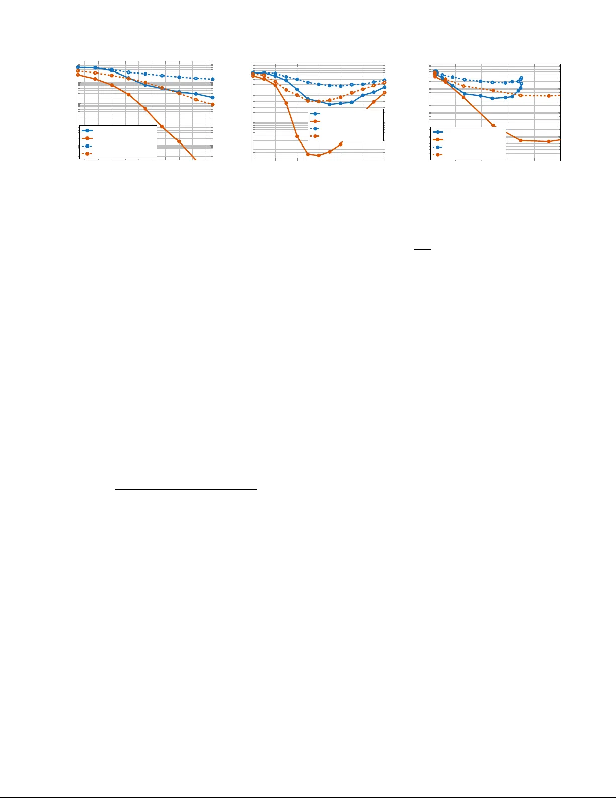
1 Cross-Pilot Superposition for Fractional P arameter Estimation in DoA-Aided O TFS Recei v ers Mauro Marchese , Graduate Student Member , IEEE , Pietro Sav azzi , Senior Member , IEEE Abstract —In this letter , a novel superimposed pilot scheme is pr oposed for channel estimation in multi-antenna orthogonal time frequency space (OTFS) receivers. Under the assumption of a large unif orm linear array (ULA) size at the receiv er , the multipath components are separated directly in the angular domain. It is then shown that the proposed superimposed pilot scheme enables the computation of integrated delay and Doppler profiles by a veraging the r eceived delay-Doppler matrix across the Doppler and delay axes, respecti vely . This procedure helps reduce data-to-pilot interference through data averaging. Moreo ver , it is demonstrated that fractional delays and Dopplers of the multipath components can be estimated by correlating the integrated delay and Doppler profiles with the corresponding delay/Doppler terms. Simulation results sho w that the pr o- posed approach outperforms existing O TFS superimposed pilot schemes, achieving a lower bit error rate (BER) while exhibiting a trade-off between peak-to-average power ratio (P APR) and communication performance. Index T erms —Channel estimation, DoA-aided, O TFS, superi- mosed pilot. I . I N T R O D U C T I O N A NGLE-domain processing allows for the separation of multipath components when the recei ver is equipped with a large antenna array [1]–[4], thereby transforming a doubly-dispersiv e channel into multiple parallel flat-fading channels. In [1]–[3], multi-antenna orthogonal frequency divi- sion multiplexing (OFDM) receivers are proposed for reliable communications under receiv er mobility [1], [2] and the mo- bility of both transceiv ers and scatterers [3]. Similarly , as the orthogonal time frequency space (O TFS) wa veform proposed in [5] has gained significant attention for the dev elopment of next-generation wireless systems, a multi-antenna receiver is designed in [4] to separate multipaths in the angular domain. This approach increases sparsity in the delay-Doppler domain and reduces the data detection complexity of the message passing (MP) algorithm. Howe ver , [4] assumes ideal channel estimation. The channel estimation problem in O TFS has been addressed in sev eral works [6]–[15]. Embedded-pilot and full- pilot schemes have been in vestigated in [6]–[8] and [9]–[11], respectiv ely . The algorithm in [6] assumes integer delays and Doppler shifts, thereby exhibiting performance degradation in real-world scenarios with fractional delays and Doppler shifts [8]–[11]. The problem of fractional parameter estimation M. Marchese is with the Department of Electrical, Computer and Biomedical Engineering, University of Pavia, 27100 Pavia, Italy (e-mail: mauro.marchese01@univ ersitadipavia.it). Pietro Savazzi is with the Department of Electrical, Computer and Biomedical Engineering, University of Pavia, Pa via, 27100 Italy (e-mail: pietro.sav azzi@unipv .it), and with the Consorzio Nazionale Interuni versitario per le T elecomunicazioni - CNIT . has been addressed in [7] and further in vestigated in [8]– [11]. Specifically , in [7], [8], [11], disjoint delay-Doppler estimation is performed, reducing complexity compared to joint delay-Doppler estimation [9], [10]. Superimposed pilot schemes have been introduced in the literature [12]–[15] to increase spectral efficienc y compared to embedded-pilot and full-pilot approaches. Single-pilot and multiple-pilot schemes hav e been proposed in [12] and [15], respectiv ely . Moreover , in [15], it is shown that the multiple superimposed pilot scheme outperforms embedded-pilot and single superimposed pilot schemes by achieving higher throughput. Ho wev er , in superimposed pilot approaches, it is typically assumed that the channel consists of integer delays and Doppler shifts [12]– [15]. In light of the above discussion, this letter proposes a novel superimposed pilot scheme, termed superimposed cross-pilots , for direction-of-arri v al (DoA)-aided O TFS-based recei vers. It is demonstrated that the proposed scheme enables the computation of integrated delay and Doppler profiles through av eraging. This procedure effecti vely reduces data-to-pilot in- terference, eliminating the need for iterati ve schemes required by state-of-the-art superimposed pilot approaches [15]. Finally , based on the proposed scheme, a low-complexity disjoint fractional delay-Doppler estimation algorithm is designed. I I . S Y S T E M M O D E L The scenario includes a single-antenna transmitter (TX) and a multi-antenna receiv er (RX) equipped with a uniform linear array (ULA) with N r receiving antennas and working at carrier frequency f c . The TX sends to the RX an O TFS frame including M delay bins and N Doppler bins. Therefore, the O TFS transmit signal is made of M subcarriers with spacing ∆ f = 1 /T , where T is the symbol duration, and N time slots. Thus, the signal bandwidth is B = M ∆ f . The TX adopts cyclic prefix (CP)-OTFS, meaning that each block of the transmit O TFS frame is preceded by a CP with duration T P C > σ τ to pre vent intersymbol interference (ISI), where σ τ is the channel delay spread. Hence, the ov erall symbol duration is T ′ = T C P + T and the frame duration is T f = N T ′ . A. Single-Antenna O TFS T ransmitter The O TFS modulator arranges M N symbols in the delay- Doppler (DD) domain over the two-dimensional grid I DD = m ∆ τ , n ∆ ν | 0 ≤ m ≤ M − 1 , 0 ≤ n ≤ N − 1 , where ∆ τ = 1 /B and ∆ ν = 1 /T f represent the delay and Doppler resolutions, respectiv ely . Hence, the DD matrix X ∈ C M × N is obtained. The TX uses N p superimposed pilots for channel estimation. Therefore, X = p E s X d + p E p X p ∈ C M × N , (1) 2 where X d contains quadrature amplitude modulation (QAM) data with E [ X d ] m,n 2 = 1 and X p contains pilot symbols such that [ X p ] m,n = 1 if ( m, n ) = ( m (1) p , n (1) p ) , ( m (2) p , n (2) p ) , . . . , ( m ( N p ) p , n ( N p ) p ) , and [ X p ] m,n = 0 otherwise. Moreover , E s is the average energy per symbol allocated for data and E p is the pilot ener gy . The total energy is split between pilot and data by fixing the pilot-to-data ratio (PDR), which is defined as PDR = E p /E s . The TX is subject to an a verage power constraint so that to total ener gy per frame E f = M N E s + N p E p is fixed. The transmit vector is obtained via inv erse discrete Zak transform (IDZT) as s = F H N ⊗ I M x ∈ C M N , (2) where [ F N ] p,q = 1 √ N e − j 2 π pq N is the N -point unitary discrete Fourier transform (DFT) matrix, I M is the identity matrix of order M and x = vec ( X ) . B. Observation Model at the Multi-Antenna Receiver The transmit signal passes through a doubly-dispersi ve wireless channel made of P propagation paths with delay τ p , Doppler shift ν p , channel gain α p and DoA θ p . According to [11], the receiv ed time-spatial observations R ∈ C M N × N r are obtained as R = P X p =1 α p ∆ ( k p ) I N ⊗ C M ( l p ) sa ⊤ rx ( θ p ) + N , (3) where l p = τ p / ∆ τ and k p = ν p / ∆ ν are the normalized delay and Doppler shifts, respectiv ely . Moreov er , N ∈ C M N × N r is the additive white gaussian noise (A WGN) matrix and vec ( N ) ∼ C N (0 , σ 2 I M N N r ) . Noise variance is giv en as σ 2 = N 0 where N 0 is the noise po wer spectral density . Further , a rx ( θ ) is the steering vector of the ULA at the RX. It is com- puted as a rx ( θ ) = 1 e j 2 π λ d sin( θ ) . . . e j 2 π λ d ( N r − 1) sin( θ ) ⊤ assuming the antenna spacing at the RX is d = λ/ 2 , where λ = c/f c is the wa velength and c denotes the speed of light. Finally , the Doppler matrix ∆ ( k ) ∈ C M N × M N is gi ven as ∆ ( k p ) = D k p N ⊗ ˜ D k p M , (4) where D N ∈ C N × N and ˜ D M ∈ C M × M are diagonal matrices with [ D N ] n,n = e j 2 π N n and [ ˜ D M ] m,m = e j 2 π M N mT T ′ , respec- tiv ely . Moreover , D N and ˜ D M capture intersymbol and in- trasymol (i.e., intercarrier interference (ICI)) Doppler-induced phase rotations, respectiv ely . The delay matrix C M ( l p ) ∈ C M × M is a circulant matrix defined as C M ( l p ) = F H M ( D ∗ M ) l p F M , (5) where D M ∈ C M × M is a diagonal matrix with [ D M ] m,m = e j 2 π M m . The signal-to-noise ratio (SNR) is obtained as SNR = E f M N σ 2 = M N E s + N p E p M N σ 2 . (6) C. Angle-Domain Beamforming Hereafter , the following assumptions are made: (i) the DoAs are known due to previous estimation 1 , (ii) the receiver 1 The estimation of DoAs is beyond the scope of this work, which focuses on fractional delay and Doppler estimation for superimposed pilot-based angle- domain O TFS receivers. Since the proposed approach and the baseline method are ev aluated under identical operating conditions, any impairment from imperfect DoA knowledge affects both equally , ensuring a fair comparison. 0 10 0 20 40 60 0 0 . 5 1 Doppler delay (a) 0 10 0 20 40 60 0 0 . 5 1 Doppler delay (b) Fig. 1: Pilot matrix X p configurations: (a) multiple pilot scheme [15] and (b) proposed cross-pilot scheme. is equipped with a large ULA (the number of antennas is suf ficienlty high), so that the interpath interference (IPI) between multipaths with dif ferent angles is negligible [1], [3]. The first operation made by angle-domain based receivers is multipath separaion by means of a matched filter (MF) [1], [3]. Using the fact that a ⊤ rx ( θ 1 ) a ∗ rx ( θ 2 ) ≈ 0 if θ 1 = θ 2 and a ⊤ rx ( θ 1 ) a ∗ rx ( θ 2 ) = N r if θ 1 = θ 2 for sufficiently high N r [1], [3], multipaths are separated in the angular domain performing r p = Ra ∗ rx ( θ p ) N r ≈ α p ∆ ( k p ) I N ⊗ C M ( l p ) s + n p , (7) where n p = Na ∗ rx ( θ p ) / N r . Hence, n p ∼ C N ( 0 M N , σ 2 I M N / N r ) . After that, the signal in (7) is con verted to delay-Doppler domain via discrete Zak transform (DZT) as y p = F N ⊗ I M r p ≈ α p F N ⊗ I M ∆ ( k p ) F H N ⊗ C M ( l p ) x + z p = α p F N D k p N F H N ⊗ ˜ D k p M C M ( l p ) x + z p , (8) where z p = F N ⊗ I M n p is the delay-Doppler domain A WGN vector . I I I . P RO P O S E D S U P E R I M P O S E D P I L OT S C H E M E F O R D O A - A I D E D R E C E I V E R S This section presents the proposed superimposed pilot scheme and the proposed fractional delay-Doppler estimation algorithm. A. Superimposed Cr oss-Pilots Figure 1a shows the multiple superimposed pilot scheme adopted in [15]. A limitation of the multiple superimposed pilot scheme is that, in the presence of fractional channel parameters, the pilots interfere with each other due to the spreading effect [9], [11], [16]. In DoA-aided receiv ers, the following superimposed pilot scheme can be adopted, where the delay-Doppler pilots are allocated as x p = ( 1 N ⊗ e m p ) + e n p ⊗ ( 1 M − e m p ) , (9) where m p and n p represent the delay and Doppler indices over which the pilots are superimposed, respectively . Consequently , the number of superimposed pilots is N p = M + N − 1 . Figure 1b illustrates an example of the proposed pilot scheme compared to the multiple superimposed pilot scheme in [15]. B. Disjoint Delay-Doppler Estimation V ia A veraging Giv en the proposed superimposed cross-pilot scheme, it is possible to estimate delay and Doppler shifts separately 3 as follows. The delay profile is obtained by a veraging the columns of the delay-Doppler matrix Y p = vec − 1 ( y p ) as u p = Y p 1 N N = ( 1 ⊤ N ⊗ I M ) y p N ∈ C M . (10) Similarly , the Doppler profile is obtained by summing up the rows of Y p as v p = Y ⊤ p 1 M M = ( I N ⊗ 1 ⊤ M ) y p M ∈ C N . (11) Lemma 1. The integr ated delay profile in (10) is given by 2 u = α p E p N g u ( l, k ) + √ E s N ˜ D k M C M ( l ) N − 1 X n =0 [ X d ] : ,n + ˜ z u , (12) wher e ˜ z u ∼ C N 0 M , σ 2 N N r I M and g u ( l, k ) = ( N − 1) ˜ D k M F H M [ F M ] : ,m p ⊙ d − l M + ˜ d k M (13) with d M = diag D M and ˜ d M = diag ˜ D M . Pr oof. The proof relies on the Kronecker product properties and on the DFT property F N e 0 = 1 N / √ N . Combining (1), (8), (9) and plugging (8) into (10), the term related to the pilot in the delay profile becomes proportional to the following terms: ( 1 ⊤ N ⊗ I M ) F N D k N F H N ⊗ ˜ D k M C M ( l ) ( 1 N ⊗ e m p ) = 1 ⊤ N F N D k N F H N 1 N ⊗ ˜ D k M C M ( l ) e m p = N e ⊤ 0 D k N e 0 ˜ D k M C M ( l ) e m p = N ˜ D k M C M ( l ) e m p = N ˜ D k M F H M [ F M ] : ,m p ⊙ d − l M , (14) ( 1 ⊤ N ⊗ I M ) F N D k N F H N ⊗ ˜ D k M C M ( l ) ( e n p ⊗ 1 M ) = 1 ⊤ N F N D k N [ F H N ] : ,n p ⊗ ˜ D k M F H M ( D ∗ M ) l F M 1 M = √ M N e ⊤ 0 [ F H N ] : ,n p ˜ D k M F H M ( D ∗ M ) l e 0 = ˜ D k M 1 M , (15) ( 1 ⊤ N ⊗ I M ) F N D k N F H N ⊗ ˜ D k M C M ( l ) ( e n p ⊗ e m p ) = ˜ D k M C M ( l ) e m p = ˜ D k M F H M [ F M ] : ,m p ⊙ d − l M . (16) Moreov er , the term related to data becomes proportional to ( 1 ⊤ N ⊗ I M ) F N D k N F H N ⊗ ˜ D k M C M ( l ) x d = √ N e ⊤ 0 D k N F H N ⊗ ˜ D k M C M ( l ) x d = 1 ⊤ N ⊗ ˜ D k M C M ( l ) x d , (17) where the last equality implies that the data term is propor - tional to the average of the columns of the data symbol matrix X d . This av eraging reduces the power of the interfering data by a factor of N . In fact, as the frame size increases, the data-to-pilot interference tends to zero lim N →∞ 1 N N − 1 X n =0 [ X d ] : ,n = E h [ X d ] : ,n i = 0 M . (18) The same av eraging procedure applies to the noise, thereby reducing the noise power by a factor of N . Lemma 2. Assuming k ≪ N (negligible ICI), the inte grated 2 The subscript p , indicating the path brench, is omitted to lighten the notation in both the statement of the Lemma and the proof. Algorithm 1: Proposed fractional delay-Doppler esti- mation using superimposed cross-pilots Input: R , x p , { θ p } P p =1 for p = 1 to P do r p = Ra ∗ rx ( θ p ) N r ; y p = F N ⊗ I M r p ; v p = ( I N ⊗ 1 ⊤ M ) y p ; ˆ k p = arg max k g H v ( k ) v p ; u p = ( 1 ⊤ N ⊗ I M ) y p ; ˆ l p = arg max l g H u ( l, ˆ k p ) u p ; ˆ α p = D ˆ k p N F H N ⊗ ˜ D ˆ k p M C M ( ˆ l p ) x p H r p N p E p ; Output: { ˆ α p , ˆ l p , ˆ k p } P p =1 ; Doppler pr ofile in (11) can be appr oximated as v ≈ α p E p M g v ( k ) + √ E s M F N D k N F H N M − 1 X m =0 X ⊤ d : ,m + ˜ z v , (19) wher e ˜ z v ∼ C N ( 0 N , σ 2 M N r I N ) and g v ( k ) = ( M − 1) F N F H N : ,n p ⊙ d k N + 1 N (20) with d N = diag D N . Pr oof. The proof relies on the approximation ˜ D k M ≈ I M , which holds if k ≪ N . Combining (1), (8) and (9), and plugging (8) into (11), the term related to the pilot in the Doppler profile becomes proportional to the following terms: ( I N ⊗ 1 ⊤ M ) F N D k N F H N ⊗ ˜ D k M C M ( l ) ( 1 N ⊗ e m p ) ≈ F N D k N F H N 1 N ⊗ √ M e ⊤ 0 ( D ∗ M ) l F M e m p = √ N F N D k N e 0 = 1 N , (21) ( I N ⊗ 1 ⊤ M ) F N D k N F H N ⊗ ˜ D k M C M ( l ) ( e n p ⊗ 1 M ) ≈ F N D k N F H N e n p ⊗ 1 ⊤ M F H M ( D ∗ M ) l F M 1 M = M e ⊤ 0 ( D ∗ M ) l e 0 F N D k N [ F H N ] : ,n p = M F N F H N : ,n p ⊙ d k N , (22) ( I N ⊗ 1 ⊤ M ) F N D k N F H N ⊗ ˜ D k M C M ( l ) ( e n p ⊗ e m p ) ≈ F N F H N : ,n p ⊙ d k N . (23) Moreov er , the term related to data becomes proportional to ( I N ⊗ 1 ⊤ M ) F N D k N F H N ⊗ ˜ D k M C M ( l ) x d ≈ √ M F N D k N F H N ⊗ e ⊤ 0 ( D ∗ M ) l F M x d = F N D k N F H N ⊗ 1 ⊤ M x d , (24) where the last equality implies that the data term is propor - tional to the average of the rows of the data symbol matrix X d . This reduces the po wer of the interfering data by a factor of M . In fact, as the frame size increases, the data-to-pilot interference tends to zero lim M →∞ 1 M M − 1 X m =0 [ X ⊤ d ] : ,m = E h [ X ⊤ d ] : ,m i = 0 N . (25) As with the delay profile, the same averaging procedure applies to the noise, thereby reducing its impact. Based on the results presented in Lemma 1 and Lemma 2, disjoint delay-Doppler estimation can be performed as follo ws. 4 − 14 − 12 − 10 − 8 − 6 − 4 − 2 0 2 4 10 − 4 10 − 3 10 − 2 10 − 1 10 0 Signal-to-Noise Ratio (SNR) [dB] BER 4 -QAM, baseline [15] 4 -QAM, proposed 16 -QAM, baseline [15] 16 -QAM, proposed (a) The bit error rate (BER) is shown against SNR. The PDR is fixed to PDR = − 5 dB. − 20 − 15 − 10 − 5 0 5 10 10 − 3 10 − 2 10 − 1 10 0 PDR [dB] BER 4 -QAM, baseline [15] 4 -QAM, proposed 16 -QAM, baseline [15] 16 -QAM, proposed (b) The BER is shown against the PDR. The SNR is fixed to SNR = − 2 dB. 8 10 12 14 16 18 10 − 4 10 − 3 10 − 2 10 − 1 10 0 P APR [dB] BER 4 -QAM, baseline [15] 4 -QAM, proposed 16 -QAM, baseline [15] 16 -QAM, proposed (c) The BER vs peak-to-av erage power ratio (P APR) trade- off. The curves are obtained by sweeping the PDR in the range [ − 20 , 10] dB. Fig. 2: Simulation results Since the CP prev ents ISI, as shown in (19), the Doppler profile is independent of the delay . Therefore, the Doppler shift can be estimated through a MF as ˆ k p = arg max k g H v ( k ) v p . (26) In contrast, due to the presence of ICI, the delay profile in (12) depends on both Doppler and delay shifts. Thus, the delay can be estimated after obtaining the Doppler estimate as ˆ l p = arg max l g H u ( l, ˆ k p ) u p . (27) The maximization in (26) and (27) is carried out in two steps: (i) a coarse estimate of the integer part is obtained by identifying the absolute peak of the integrated delay and Doppler profiles; (ii) the search space is narrowed to include fractional delays and Doppler shifts around the initial estimates (specifically l ∈ [ ˆ l − 0 . 5 , ˆ l + 0 . 5] and k ∈ [ ˆ k − 0 . 5 , ˆ k + 0 . 5] ) to maximize the correlation via MFs. Once the delay-Doppler pairs are determined, the channel gain of the p -th path is obtained via least squares (LS) estimation as ˆ α p = D ˆ k p N F H N ⊗ ˜ D ˆ k p M C M ( ˆ l p ) x p H r p N p E p . (28) The details of the proposed approach are provided in Algo- rithm 1. It can also be noted that the complexity of the pro- posed estimation algorithm is O ( P ( M N N r + M N log 2 N )) . Under the assumption of a lar ge-scale antenna array at the receiv er, where the number of antennas N r is suf ficiently high such that N r ≫ log 2 N , spatial processing becomes the dominant factor .Consequently , the complexity simplifies to O ( P M N N r ) , thus scaling linearly with the system param- eters. I V . S I M U L A T I O N R E S U LT S T o e valuate the performance of the proposed approach, simulations are conducted considering a carrier frequency f c = 5 . 9 GHz with a subcarrier spacing ∆ f = 30 kHz. The O TFS system employs M = 64 subcarriers and N = 16 blocks, while the receiver is equipped with N r = 32 antennas. The wireless channel is characterized by P = 4 multipath components with propagation delays τ p = [0 , 0 . 9 , 2 . 4 , 3] µ s, av erage path powers P p = [0 , − 1 , − 5 , − 7] dB, and DoAs θ p = [10 ◦ , 42 ◦ , − 25 ◦ , 24 ◦ ] . T o simulate high-mobility con- ditions, a maximum speed v max = 500 km/h is assumed, with Doppler shifts ν p = f c v max c cos( ϕ p ) , where ϕ p ∼ U [0 , 2 π ] . The proposed approach is compared against the multiple superimposed pilot scheme in [15]; for data detection, a path- wise MF is applied, follo wed by maximum ratio combining (MRC). Fig. 2a illustrates the BER performance as a function of the SNR. It is observed that the baseline scheme suffers significant performance degradation due to the presence of fractional delays and Doppler shifts. Conv ersely , the proposed method effecti vely accounts for fractional channel parameters, thereby achieving a lo wer BER. The impact of the PDR on com- munication performance is analyzed in Fig. 2b. A lo w PDR allocates more energy to data symbols, potentially facilitating detection, but reduces the energy av ailable for pilots, which impairs channel estimation accuracy . In contrast, a higher PDR enhances pilot energy and estimation precision at the expense of the data SNR. This inherent trade-of f leads to an optimal PDR that minimizes the BER [16]. As shown in Fig. 2b, the minimum BER is reached at a PDR of approximately − 5 dB and − 2 dB for the proposed and baseline methods, respectiv ely . Finally , Fig. 2c depicts the trade-off between P APR and BER for both schemes across various PDR values. Although the proposed scheme exhibits a higher P APR for a fixed PDR, it provides a lower BER when compared at a target P APR le vel, demonstrating its superior efficiency . V . C O N C L U S I O N In this letter , a no vel O TFS superimposed cross-pilot scheme for DoA-aided multi-antenna receivers has been proposed. By exploiting the angular separability of multipaths, it has been demonstrated that the proposed scheme enables the integration of received delay-Doppler matrices; this reduces the effecti ve data-to-pilot interference through averaging, thereby eliminat- ing the need for complex iterativ e cancellation. Furthermore, a lo w-complexity disjoint estimation algorithm has been de- veloped to accurately estimate fractional delays and Doppler shifts. Simulation results confirm that the proposed scheme achiev es a significantly lo wer BER compared to state-of- the-art superimposed approaches in high-mobility scenarios, while providing a manageable trade-of f between P APR and communication performance. 5 R E F E R E N C E S [1] Y . Ge, W . Zhang, F . Gao, and H. Minn, “Angle-Domain Approach for Parameter Estimation in High-Mobility OFDM W ith Fully/Partly Cali- brated Massive ULA, ” IEEE T ransactions on W ireless Communications , vol. 18, no. 1, pp. 591–607, 2019. [2] W . Guo, W . Zhang, P . Mu, and F . Gao, “High-Mobility OFDM Downlink T ransmission W ith Large-Scale Antenna Array, ” IEEE Tr ansactions on V ehicular T echnology , vol. 66, no. 9, pp. 8600–8604, 2017. [3] M. Marchese, M. F . Keskin, H. W ymeersch, and P . Savazzi, “6G OFDM Communications with High Mobility Transcei vers and Scatterers via Angle-Domain Processing and Deep Learning, ” 2026. [Online]. A vailable: https://arxiv .org/abs/2601.12970 [4] J. Cheng, C. Jia, H. Gao, W . Xu, and Z. Bie, “OTFS Based Receiv er Scheme with Multi-Antennas in High-Mobility V2X Systems, ” in 2020 IEEE International Conference on Communications W orkshops (ICC W orkshops) , 2020, pp. 1–6. [5] R. Hadani, S. Rakib, M. Tsatsanis, A. Monk, A. J. Goldsmith, A. F . Molisch, and R. Calderbank, “Orthogonal Time Frequency Space Mod- ulation, ” in 2017 IEEE W ir eless Communications and Networking Con- fer ence (WCNC) , 2017, pp. 1–6. [6] P . Raviteja, K. T . Phan, and Y . Hong, “Embedded Pilot-Aided Channel Estimation for O TFS in Delay–Doppler Channels, ” IEEE T ransactions on V ehicular T echnology , vol. 68, no. 5, pp. 4906–4917, 2019. [7] I. A. Khan and S. K. Mohammed, “A Low-Complexity O TFS Chan- nel Estimation Method for Fractional Delay-Doppler Scenarios, ” IEEE W ireless Communications Letters , vol. 12, no. 9, pp. 1484–1488, 2023. [8] V . Y ogesh, S. R. Mattu, and A. Chockalingam, “Low-Complexity Delay- Doppler Channel Estimation in Discrete Zak Transform Based O TFS, ” IEEE Communications Letters , vol. 28, no. 3, pp. 672–676, 2024. [9] S. P . Muppaneni, S. R. Mattu, and A. Chockalingam, “Channel and Radar Parameter Estimation With Fractional Delay-Doppler Using O TFS, ” IEEE Communications Letters , vol. 27, no. 5, pp. 1392–1396, 2023. [10] M. Marchese, H. W ymeersch, P . Spallaccini, and P . Sav azzi, “Progressive Inter-P ath Interference Cancellation Algorithm for Channel Estimation Using Orthogonal T ime–Frequency Space, ” Sensors , vol. 24, no. 4414, 2024. [Online]. A vailable: https://doi.org/10.3390/s24134414 [11] M. Marchese, M. F . Keskin, P . Sav azzi, and H. W ymeersch, “Disjoint Delay-Doppler Estimation in O TFS ISAC with Deep Learning-aided Path Detection, ” 2025. [Online]. A vailable: https: //arxiv .org/abs/2504.20659 [12] W . Y uan, S. Li, Z. W ei, J. Y uan, and D. W . K. Ng, “Data-Aided Channel Estimation for OTFS Systems W ith a Superimposed Pilot and Data T ransmission Scheme, ” IEEE W ireless Communications Letters , vol. 10, no. 9, pp. 1954–1958, 2021. [13] H. B. Mishra, P . Singh, A. K. Prasad, and R. Budhiraja, “O TFS Channel Estimation and Data Detection Designs W ith Superimposed Pilots, ” IEEE T ransactions on W ireless Communications , vol. 21, no. 4, pp. 2258–2274, 2022. [14] F . Jesbin, S. Rao Mattu, and A. Chockalingam, “Sparse Superimposed Pilot Based Channel Estimation in OTFS Systems, ” in 2023 IEEE W ireless Communications and Networking Conference (WCNC) , 2023, pp. 1–6. [15] Y . Kanazawa, H. Iimori, C. Pradhan, S. Malomsoky , and N. Ishikaw a, “Superimposed Pilot-Based O TFS – W ill it W ork?” 2025. [Online]. A vailable: https://arxiv .org/abs/2501.15935 [16] M. Marchese and P . Sav azzi, “Robust 6G OFDM High-Mobility Communications Using Delay-Doppler Superimposed Pilots, ” 2025. [Online]. A vailable: https://arxiv .org/abs/2512.16496
Original Paper
Loading high-quality paper...
Comments & Academic Discussion
Loading comments...
Leave a Comment