Dual-Hop Joint Visible Light and Backscatter Communication Relaying under Finite Blocklength
This paper investigates a dual-hop joint visible light communication (VLC) and backscatter communication (BC) relaying framework under the finite blocklength (FBL) constraint, aiming at energy-neutral Ambient Internet of Things (A-IoT) deployments. I…
Authors: Boxuan Xie, Lauri Mela, Alexis A. Dowhuszko
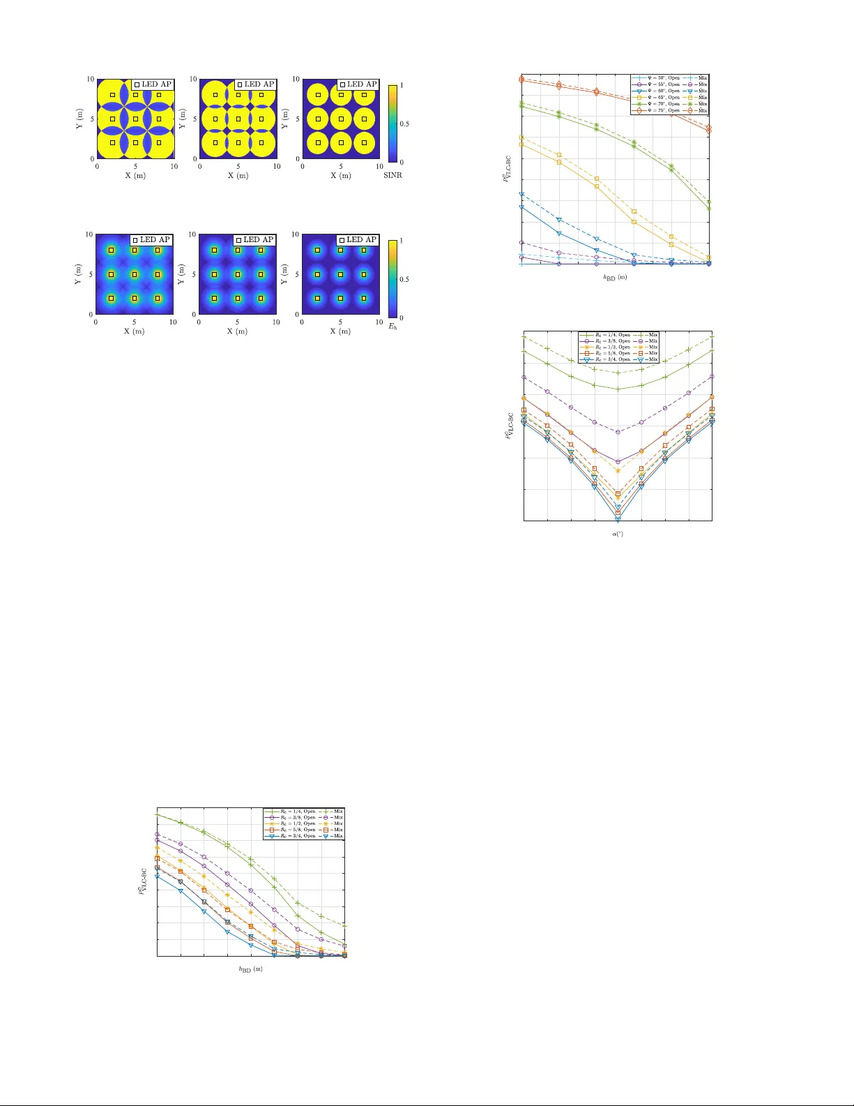
Dual-Hop Joint V isible Light and Ba ckscatter Communication Relaying under Finite Blocklength Boxuan Xie ∗ , Lauri Mela ∗ , Alexis A. Do whuszko ∗ , Jiacheng W ang † , Kalle Ruttik ∗ , Riku J ¨ antti ∗ ∗ Departmen t of Info rmation and Communic a tions Engine ering, Aalto University , 0215 0 Espoo , Finland † College of Compu ting and Data Science , Nanyan g T echnological University , Singapore 63 9 798 Abstract —This paper in vestigates a dual-hop joint visible light communication (VLC) and b ackscatter communication (BC) re- laying framew ork u nder the finite blocklength (FBL) constraint, aiming at energy-neutral Ambient Inter net of Things (A-IoT) deployments. In the proposed system, indoor LED access p oints are used to simultaneously provide illumination and transmit informa tion ov er light to a bac kscatter device (BD), which harv ests optical energy and backscatters th e rece ive d messages to u ser equipments ( UEs) equip ped with radio frequency (RF) front ends. This fo rwarding of the information from VLC to RF channels is implemented without the need for carrier synthesizers and po wer amplifiers at the IoT node. By modeling th e end-to-end communication link with short-pack et IoT traffic and realistic lev els of interference between adjacent VLC cov erage areas, we analyze the outage p erf ormance and achiev able data rate of the proposed system. Simulation results demonstrate that key factors, such as placement and orientation of the BD, as well as th e selected code rate of the system affect reliability and data rate that can be achi eved for communication purposes. The in sights gained from this study pa ve the way f or ambient power -enabled IoT solutions and fu t u re hybrid VLC/RF network d esigns. Index T erms —Ambi ent IoT , hybrid VLC/R F , visible li ght communication, b ackscatter communication, re lay , short p acket. I . I N T RO D U C T I O N W ith the a d vent of the sixth gener ation (6G) er a , visible light commun ication (VLC) has emerged as a key en a bling technolog y fo r th e energy-efficient con nectivity of Inte r net of Thing s ( IoT). VLC le verages the ubiqu ito us light-emitting diode ( LED) infrastructu re fo r bo th indo or illumin a tion and wireless data transmission, thereby addressing the dual need s of ligh ting an d conn ecti vity . VLC-en abled I oT solution s ar e attractive bec a use of their ad vantages in energy con sumption and spectrum utilization [ 1 ]. Recen t advances prop ose hy- brid indoor wireless networks that com bine VLC with radio frequen cy ( RF) comm u nications, enhan ced b y simultaneou s lightwav e infor mation an d power transfe r (SLI PT ) [ 2 ], [ 3 ]. This method har nesses th e capability of VLC to conv ey both informa tio n and power to IoT devices, supporting b attery-free operation s rang ing from smart homes to indu strial a u tomation. Despite its prom ising pr ospects, the deployment of VLC- enabled I oT systems faces several challenges. Ex isting solu- tions in this regard typically r equire complex recep tion and relaying mechanisms, o ften relyin g on sensitive photod etectors and retroreflectors to forward VLC signa ls from LED acce ss This work is partially supported by the funding through AMBIENT -6G project under the European Union’ s Horizon Europe research and innov ation programme (Grant Agreement No 101192113), and the W ALL P APER project from Research Council of Finland (Grant Agreement No 352912). points (APs) to the target receiver . An a lternative appro ach in volves conv erting the incoming VLC sign als into ou tgoing RF signals, wh ic h are fo rwarded using an intermed iate Io T node. Several stud ies have propo sed VLC-RF relaying ar- chitectures wh ere the VLC signal is received, d ecoded, an d then enco ded ag ain for its transmission in the RF domain such that con ventional RF rec e i vers can process the data [ 4 ], [ 5 ]. However , the se meth o ds assume the pr esence of p ower amplifiers and active RF tra nsmitters in the relay nodes, which increases h ardware complexity an d imp le m entation costs. Fur- thermor e , existing works often overlook the impact o f th e finite blocklen gth (FBL) traffic, a cr itica l factor in short-p acket commun ications that is co mmonly co nsidered in practical IoT network s [ 6 ], [ 7 ]. Th is oversight u n derscores the need for system mo d els that fully account fo r the n on-asymp totic perfor mance of IoT application s. Recent ad vances in A m bient IoT within the 3rd Generation Partnership Project (3GPP) h ave undersco r ed the po tential of ultra-low-power backscatter comm unication (BC) as a fo un- dational technolog y fo r 6G cellular I o T networks [ 8 ], [ 9 ]. In BC scenarios, backscatter devices ( BDs) r ely on existing RF signals fo r carrier m odulation , elimin ating the ne ed fo r energy- intensive RF compon ents, such a s local oscillators and power amplifiers [ 10 ]. In this con text, integrating VL C with BC offers a pro mising alternative to hybr id VLC/RF systems for VLC- RF r e la y ing. Ear ly studies have shown that low-complexity BDs can relay inf ormation from LED APs to RF rece ivers without the strict hard ware require ments of existing acti ve relays [ 11 ]–[ 13 ]. However , compr ehensive system mo deling and rigo rous perf o rmance an alysis o f su ch systems rem a in unexplored . This paper addresses the se gap s by in vestigating a du al-hop VLC-BC relay ing scheme u nder FBL constraints in an indoo r environment with multiple LED APs. Ke y con- tributions of this pape r are outlin e d as follows: • W e inv estigate a d ual-hop VLC-BC relayin g schem e fo r indoor hybrid VLC/RF systems, w h ere a BD receiv es VLC messages and relays the m to user equipm ents (UEs) equippe d with RF r e c ei vers. This is achiev ed by modu- lating the ph otovoltaic-con verted message with ambient RF car rier waves emitted by an RF source (RFS). • W e d e velop a compr ehensive system mode l in corpor a ting the effect of FBL traffic, which represents a critical factor f o r short-packet Io T transmissions. W e also derive expressions for the outage proba bility a nd ach iev ab le data rate of the system, q u antifying the system perform ance Light-Interfering Area UE RFS UE . F C C sc Fig. 1. System model. under the p ractical FBL constraint. • W e analyz e the effect o f placemen t and orien tation of the BD on overall link qua lity und er illumination from multiple LED APs. W e ado pt the 3GPP Ind oor Hotspo t channel model to assess th e com munication pe rforman ce under different indoo r radio p ropagatio n conditions. The rest o f th e paper is organized as follows. Section II propo ses the system mo del. Sec tio n III analyzes co mmuni- cation outage per formanc e of the system. Section IV p resents and evaluates the simu lation results. Finally , Sec tion V draws conclusion s and discusses future work . I I . S Y S T E M M O D E L The prop osed d u al-hop VLC-BC relaying sy stem is illus- trated in Fig. 1 and the schema tic d iagram is p resented in Fig. 2 . In th e first h op (VLC link), LED APs transmit VL C signals usin g an intensity modula tio n/direct d etection (IM/DD) scheme to carry mod ulated messages, w h ich are re c e i ved by a BD within their coverag e ar eas. The BD g enerally consists of a pho todetector, an energy harvester, a b ackscatter modulato r , an d an RF antenna [ 11 ], [ 12 ]. For the p roposed system targeting low-data-rate comm u nications, this p aper considers th e use of photovoltaic cells as the ph otodetector . The alternatin g cur rent/direct cu r rent ( AC/DC) splitter sep - arates the pho tov oltaic-converted sign als in to electrical A C and DC comp onents. Th e AC compo nent, which c a rries the VLC messages, is used to contr ol the backscatter modu latio n, whereas the DC componen t supplies energy to the BD. In the second ho p (BC link), the BD modulates am bient RF carrier wa ves, such as those emitted by an indoo r RFS which could typically b e, e.g ., a W iFi AP . Th e mo dulation is controlled by the A C comp onent wh ich alternates the re flec tio n coefficients of the BD. The mod ulated sign a l is then back scattered and captured by UEs eq u ipped with RF fron t ends. Sub sequently , the VLC and BC links are modeled , respectively . A. VLC Channel Model (the first hop) The d ownlink VL C tran smission mod el fro m LED APs to the BD is co nsidered for SLIPT , serving bo th communica tio n Information source Electrical modulator Bias tee LED Ambient RF source Energy harvester Backscatter modulator DC source AC/DC splitter UE LED AP BD power VLC link (The 1st hop) BC link (The 2nd hop) Photo- detector Fig. 2. Schema tic of joint VLC-BC relaying framew ork. and energy harvesting p urposes. 1) W aveform Design and Commun ication: In the downlink direction of th e VLC tran smission, each LED AP is assign ed a unique identifier and tran smits its individual VLC signal using a time-d i vision multiplexing (TDM) meth od. On-o ff keying (OOK) b aseband mod ulation is u sed to gen erate the A C c u rrent that m odulates the inten sity o f the lig ht emitted by the LED, while a bias tee is employed to add a DC bias to the mod ulating signal. Let m ( t ) den o te the m odulating signal. Then, the elec trical signal that driv es the k -th LED AP can be written as s k ( t ) = m k ( t ) + I Bias . Th us, the transmitted optical signal ca n be expressed by [ 2 ] P LED k ( t ) = η E-O ( m k ( t ) + I Bias ) , (1) where η E-O is the LED power electric- optical conversion factor , and I Bias represents the DC curren t driving the LED. Since a practica l L ED transmitter operates within a limited linear region, the peak amplitude s max of s k ( t ) should be bo u nded to av o id c lip ping. Specifically , s max ≤ min ( I Bias − I min , I max − I Bias ) , where I max and I min denote the maximum and minimum driving current, respectively . T o characterize the VLC channel, a direct illum ination model is ad opted, based on the assumption th a t the direct optical signa l is significantly stro nger than any reflected signals [ 14 ]. Phosphor-coated LEDs are consider ed in this paper, which are assumed to em it light following Lamb ertian radiation patterns, as illustrated in Fig. 1 . Let K ≥ 1 represent th e to tal n umber of LED APs, in cluding LE D-1, LED-2 , . . . , LED- K , each of them maintainin g a line-o f-sight (LoS) link to the BD within its coverage area. For simplicity , this work assumes that the BD and its photode tec tor shar e the same position. The DC g ain of the optical chann el between LED- k and BD-equipp ed photod etector can be expressed as [ 14 ] H VLC k = ( ( ν +1) A PD 2 π d 2 k cos ν ( φ k ) cos( ψ k ) , | ψ k | ≤ Ψ , 0 , | ψ k | > Ψ , (2) where d k denotes the Eu c lidean distance between LED- k and the BD, while ν = − 1 / log 2 [cos(Φ max )] re fers to the Lambertian index of the LEDs. The p arameter Φ max indicates the semi-ang le at half- power of the LED luminair e, whe r e Ψ defines the field-of - view (FoV) sem i-angle of the BD-equip ped photod etector with an active area of A PD . Furtherm ore, φ k ≥ 0 and ψ k are the irradian ce an d inc id ence angles of the LoS link between LED- k and the BD, re sp ecti vely . The orienta tio n of th e BD, which is given by α k = φ k − ψ k , represents the a ngular deviation of th e direction wh ere the axis of the acceptance cone of the BD-equippe d ph otodetector is po inting with respect to the u pward dir ection. More over , the radiu s of the 2D coverage area of LED- k [ 14 ] can be written by r k = ( h LED − h BD ) tan (Ψ + α k ) , where h LED and h BD are the heigh ts o f the L ED and the BD, r espectiv ely . The BD-equippe d photo detector outputs electrical current i PD ( t ) = η O-E Σ K i =1 P LED i H VLC i + n ( t ) = I AC ( t ) + I DC ( t ) + n ( t ) , (3) where η O-E is th e ph otodetector respon si vity , I AC ( t ) a n d I DC ( t ) are th e AC and DC compo nents, a n d n ( t ) is ad- ditiv e white Gaussian noise with variance N 0 B , with N 0 being the noise power spectral d ensity and B the system operation al bandwidth . Fu rthermor e, th e ou tput AC com- ponen t carrying the VLC m essage can be expressed by I AC ( t ) = η O-E Σ K i =1 η E-O H VLC i m i ( t ) . For a dedicated VLC link between L ED- k and th e BD, VLC signals transmitted from other LED APs are treated as co -channe l in terference. Thus, the signal-to- noise-plus-in te r ference ratio (SI NR) o f the re - ceiv ed VLC sign al at the inpu t at the BD is g i ven by γ SINR k = η O-E P LED k H VLC k η O-E Σ K i =1 ,i 6 = k P LED i H VLC i + N 0 B . (4) 2) Energy Ha rvesting: T o supply the energy that is needed to p ower up the BD circuitry , e.g. , the back scatter modulator, energy h arvesting is performe d using the DC co m ponent output f rom th e BD-equip ped pho todetector [ 4 ]. The amo u nt of energy that can be harvested upon reception of the V L C signal ca n be written b y E h = εI DC V OC = εη O-E Σ K i =1 η E-O H VLC i I Bias V OC , (5) where ε is the fill factor of the photodetec tor , V OC is th e open circuit voltage given by V OC = V t ln 1 + η O-E Σ K i =1 η E-O H VLC i I Bias I 0 ! , (6) where V t is the ther mal voltage and I 0 is the dar k saturatio n current of th e BD-equipp e d p hotodetecto r . B. Backscatter Chann el Mode l (the second ho p) The BC link inv o lves an RFS, a BD, and UE s equip ped with RF receivers. The BD m odulates the carrier s emitted b y the RFS u sing ph otovoltaic-con verted VLC signa ls, and sub- sequently , back scatters the mo dulated signal to the UEs. The received b ackscatter sign al at the UE can then be expressed as [ 15 ] y ( t ) = p ξ G T G R G BD h f ( t ) h b ( t ) c ( t ) I AC ( t ) + n ( t ) , (7) where ξ deno tes the back scatter efficiency of th e BD, and G T , G R , and G BD are th e anten na gains o f the RFS, UE, and BD, r espectiv ely . The sym bol h f is the forward ch annel gain (RFS → BD) and h b is the b ackscatter ch annel gain (BD → UE) between the RFS and BD, a n d between the BD and UE, respectively . The amb ient RF signa l c ( t ) coming fro m the RFS ha s a power of P c = E {| c ( t ) | 2 } . Fu rthermor e, I AC ( t ) represents the AC c o mponen t of the p h otovoltaic-con verted signal that is used to m o dulate th e RF carriers. The term n ( t ) is additive wh ite Gaussian n oise with variance N 0 B . Mo reover , ξ is r e la te d to the p olarization mismatch χ f between the RFS and BD, and χ b models the m ism a tc h between th e BD and UE. Fin a lly , the m o dulation factor of the BD is gi ven by M , and Θ r epresents an ob ject penalty , and thus the backscatter efficiency c a n be exp ressed by ξ = ( χ f χ b M ) / Θ 2 [ 15 ]. For p ractical purposes, the radio prop agation of th e f o rward and backscatter ch annels is described using th e 3GPP Indo or Hotspot mod el [ 16 ]. Th e mod e l d e fines path lo ss for LoS and non -line-of- sight (NL oS) conditio n s using ( 8 ) and ( 9 ) , respectively . The path losses are expressed a s L LoS,dB = 32 . 4 + 17 . 3 log 10 ( d 3D ) + 20 log 10 ( f c ) + ζ LoS,dB , (8) L NLoS,dB = max( L LoS,dB , 17 . 3 + 38 . 3 log 10 ( d 3D ) +24 . 9 log 10 ( f c ) + ζ NLoS,dB ) . (9) In ( 8 ) and ( 9 ), d 3D represents th e 3D Euclidean distanc e , f c is the carrier freq uency in giga h ertz, and ζ LoS,dB is the shadowing factor modeled as a logn ormal r andom variable with σ LoS = 3 for 1 ≤ d 3D ≤ 150 m. Similarly , ζ NLoS,dB is th e shadowing fac- tor with σ NLoS = 8 . 03 for 1 ≤ d 3D ≤ 150 m. Th e prob a b ility of a LoS con nection varies with the ind oor en vironmen t. In an op e n ind o or environmen t with few obstruction s, the Lo S probab ility is giv en by [ 16 ] Pr open LoS = 1 , d 2D ≤ 5 m , e − d 2D − 5 70 . 8 , 5 < d 2D ≤ 49 m , 0 . 54 e − d 2D − 49 211 . 7 , d 2D > 49 m , (10) where d 2D is the 2D Euclidean distance. I n a mixed indo or en- vironm e nt with den ser ob stacles a n d m ore complex multipath effects, the LoS prob ability is given by [ 16 ] Pr mix LoS = 1 , d 2D ≤ 1 . 2 m , e − d 2D − 1 . 2 4 . 7 , 1 . 2 < d 2D ≤ 6 . 5 m , 0 . 32 e − d 2D − 6 . 5 32 . 6 , d 2D > 6 . 5 m . (11) Finally , the exp ected value o f th e overall path loss at a giv en d istance, which combin e s the LoS a n d NLoS condition s weighted b y the ir respective p robabilities, is expressed as L dB = Pr LoS · L LoS,dB + (1 − Pr LoS ) · L NLoS,dB . (12) Hence, the signal-to-no ise ratio (SNR) of the UE-r eceiv ed backscatter sign al can b e expressed as γ SNR BC = ξ G T G R G 2 BD I 2 AC P c L − 1 f L − 1 b N 0 B , (13) where L f = | h f | − 2 and L b = | h b | − 2 represent the p ath lo ss of the f orward chann el and ba c k scatter chann el, respectively . I I I . O U TAG E P E R F O R M A N C E A N A LY S I S O F J O I N T V L C - B C R E L A Y I N G S Y S T E M I N F B L R E G I M E This sectio n analyze s the o utage perfo rmance of the pr o- posed system in the FBL regime, thereby ev alu ating the system behavior under shor t-packet traffic constraints comm on in IoT applications. Conv entional information -theoretic appro aches typically assume infinitely long co dew ords to appro ach Shan- non capacity . However , since most o f the IoT co mmunication systems un der co nsideration in volve sporad ic transmissions o f dozens or a few hu n dred b its, th e so -called in finite blo cklength approa c h does not work prop erly to assess the end- to-end perfor mance. As a result, classical asymptotic me tr ics, such as ergodic or o u tage c a pacity , are less meaningful in practice. Hence, FBL theory [ 6 ] provides a more accura te characteriza- tion of the trade-off between ach ie vable data rate, latency , and reliability for sho rt-packet tr affic, mak ing it well-suited for th e propo sed hybrid VLC-RF relaying scheme with a low-data- rate requir ement. In the FBL r egime, it is possible to captu re the p ractical effects o f blo cklength, co de ra te , and target error probab ility on achiev able data rate and outage of the system. A. Achievable Rate and Outage Pr obability of VLC Link For the VLC link between th e d edicated LED AP and the BD, a lower bou nd on the chan nel cap a city [ 14 ] is given by R VLC = B log 2 1 + e 2 π γ SINR VLC , wher e B is the system commun ication band width. In the FBL regime, we define the effecti ve SI N R as γ ′ = e 2 π γ SINR VLC , leading to a chann el dispersion ter m V VLC ( γ ′ ) = 2 γ ′ 1 + γ ′ (log 2 e ) 2 . (14) Hence, the achievable data r ate of the VLC link with FBL is approx imated by R VLC FBL = B log 2 (1 + γ ′ ) − q V VLC ( γ ′ ) u Q − 1 ( ǫ ) , (15) where u d enotes the bloc klength, i.e., the nu mber of chan nel uses, ǫ is the target error p robability , an d Q − 1 ( · ) deno tes the in verse o f th e G a ussian Q -f unction. The code rate is de fined by R c = packet size u measured in bits per channel use, wher e a lower R c indicates more re d undant c o des. An outage event for the VLC link occurs if R VLC FBL falls below the system desired data r ate threshold R th , and its pro bability is expressed b y P O VLC = P ( R VLC FBL < R th ) . (16) B. Achievable Rate and Outage Pr obability of BC Link For the BC link, Shannon capacity is g iv en by R BC ( t ) = B lo g 2 1 + γ SNR BC . In the FBL regime with A WGN, the chann el dispersio n of the back scatter link can be written as V BC ( γ SNR BC ) = 1 − 1 (1 + γ SNR BC ) 2 log 2 2 ( e ) . (17) Thus, the achiev ab le d ata rate for th e backscatter link is approx imated by R BC FBL = log 2 1 + γ SNR BC − q V BC ( γ SNR BC ) u Q − 1 ( ǫ ) . (18) T ABLE I S I M U L AT I O N P A R A M E T E R S Parameter V alue Description W × L 10 × 10 Default size of target area [m 2 ] h LED , h BD , h RFS , h UE 2.5, 1.5, 3.0, 1.5 Height of LED APs, BD, RFS, and UE [m] ( x, y ) LED (2, 2) (5, 2) (8, 2) (2, 5) (5, 5) (8, 5) (2, 8) (5, 8) (8, 8) 2D positions of LED APs [m] ( x, y ) RFS (5, 5) 2D position of RFS [m] A PD 0.05 Acti ve area of the BD-equipped photovoltai c cell [m 2 ] Φ max 60 LED radiation semi-angle at half power [deg] Ψ 60 F oV s emi-angle of the PD’ s light acceptanc e cone [deg] η E-O 20 LED power electri c-optical conversi on factor [W/A] η O-E 0.5 Responsi vity of the BD-equipped photodetector [A/W] B 50 Sy stem operational bandwidth [kHz] ε 0.75 Fill factor I Bias 0.75 LED drivi ng current [A] I 0 10 − 9 Dark saturation current [A] V t 25 × 10 − 3 Thermal voltage [V] P c 23 R FS carrier power [dBm] f c 2.45 RFS carrier frequency [GHz] G T , G R , G BD 8, 3, 1.5 Ant enna gains of RFS, UE, and BD [dBi] χ f , χ b 0.5, 0.5 Polarization mismatch M 0.5 Modulation factor Θ 0 On-object penalty [dB] u 64 C hannel uses, i.e., blocklength R c 3/4 Code rate ǫ 10 − 3 T arget error probability R th 10 Sy stem desired data rate threshold [kbit/s] N 0 -174 Noise power spectral density [dBm/Hz] ( σ LoS , σ NLoS ) (3, 8.03) Shado wing factors in the 3GPP m odel [dB] Similarly , an ou tage on the BC link occurs with a pr obability expressed by P O BC = P ( R BC FBL < R th ) . (1 9 ) C. Ov e rall Outage Pr obability Since th e system is declared in outa g e if either the VLC link or the BC link fails to m eet th e target rate R th , the overall outage p robability can b e written as P O VLC-BC = 1 − P R VLC FBL ≥ R th P R BC FBL ≥ R th , (20) assuming that the two lin ks are independe nt [ 5 ], which is equiv alent to P O VLC-BC = P O VLC + P O BC − P O VLC P O BC . I V . N U M E R I C A L R E S U LT S This section presents n u merical r e sults that illustrate the ou t- age perf o rmance and ac hiev ab le data r ate o f the joint VLC-BC relaying scheme. Simulation para meters are as fo llows: 9 LED APs are dep loyed in an indoor space measurin g 10 × 10 m 2 , with p o sitions deta iled in T ab le I . L E D APs transmit VLC signals via TDM. An RFS is de ployed at the center of the 2D area on the ceiling, emitting a 2.45 GHz car rier wa ve. The po sition o f the BD is rando mly changed within th e VLC coverage area of a dedicated LED AP , fo llowing a uniform distribution, while signals fr om o ther L ED APs are treated as light interference. Similarly , th e position o f the UE is random ly changed within the indo or space according to a uniform d istribution. A summary of pa rameters that were used to o btain the simulation results is listed in T ab le I . A total of 10 5 Monte Carlo simulations h ave been conducted to assess the overall link outag e per formanc e and achiev able data rate in the FBL regime, considerin g significant variables such as th e height an d or ientation of the BD, code rate of the end-to -end link, and indoor radio pro pagation con ditions. It is no te worthy that the sy stem operates with a limited b andwidth and low- data-rate commun ications within the scope of Am bient Io T [ 8 ]. Fig. 3 shows the SINR h eatmap for the VLC signals received by the BD across the space fo r various BD heigh ts. Fig. 3. Normaliz ed SINR of the BD-rece i ved VLC signal with differe nt BD heights: 1.3, 1.5, and 1.7 m (from left to right). Fig. 4. Normalize d BD-harv ested energy from LED APs with differe nt BD heights: 1.3, 1.5, and 1.7 m (from left to right). The color scheme, ranging from d ark to b right, represents the increase in SINR levels. The circle s indicate th e VLC coverage areas, with each LED AP h a ving its own de d icated coverage region. The overlappin g shad e d areas b etween the circles indicate regions suffering f rom strong co-channel interference emitted b y adjacent VLC coverage. As the h eight o f the BD increases, the area a ffected by light interfe r ence decrea ses. Howe ver, the overall VL C coverage area also d ecreases, lim- iting the available recep tio n area. Furthermor e, Fig. 4 shows the heatmap of energy harvested by the BD fr o m re c ei ved VLC signals acro ss the space fo r various BD h eights. I n this scenario, while operatin g within its ded ica ted VLC coverage, the BD also harvests energy fr om inter fering ligh t em itted by adjacen t LED APs. A s the vertical position of the BD increases, the harvestable energy fr om the dedicated LED AP increases d ue to the red uced distance between the m ; howe ver , the h a rvestable energy fro m adjacent LED APs decreases as a result o f diminished interferin g signal power . Fig. 5 d epicts the overall o utage p robability P O VLC-BC for various h e ights of th e BD con sidering different co de rates in the FBL regime. The o u tage proba b ility decr eases as the vertical position of the BD increases, d ue to red uced recep tio n of interfering light and c onsequently higher SINR in the 1 1.1 1.2 1.3 1.4 1.5 1.6 1.7 1.8 0 0.1 0.2 0.3 0.4 0.5 0.6 0.7 0.8 0.9 Fig. 5. Overal l outage probability versus BD heights with vary ing code rates. 1.2 1.25 1.3 1.35 1.4 1.45 1.5 1.55 1.6 1.65 1.7 0 0.1 0.2 0.3 0.4 0.5 0.6 0.7 0.8 0.9 Fig. 6. Overa ll outag e probability versus dif ferent BD heights with varyin g FoV semi-angle of BD-equip ped photode tect or . -20 -15 -10 -5 0 5 10 15 20 0 0.1 0.2 0.3 0.4 0.5 0.6 Fig. 7. Overa ll outage probability versus BD orientati ons with varying code rates. VLC link. W ith a fixed data rate thresho ld R th = 10 kbps for the en d-to-end link, the use of a higher code rate R c with less redundan cy results in a lower outage prob ability by improving the effecti ve data rate. Furtherm ore, the presented result distinguishes between open- indoor and mixed-in door radio propaga tio n co nditions f or the BC link, r epresented by solid and dashed line s, respectively . Ou tage perf ormance in an o pen-indo or environment con sistently outperf orms that in a mixed-indo or environment, as the former offers a higher LoS pro bability for the BC lin k. Further more, Fig . 6 presen ts the overall o utage p r obability for various BD heigh ts und er different FoV semi-an gles of the BD-eq uipped pho todetector . Similarly , the o utage decreases as th e vertical position of the BD incr e a ses, while a smaller FoV leads to a lower outage probab ility by cap turing less interfering light. Fig. 7 shows the overall o u tage pro bability fo r various BD orientation s at different code rates in the FBL regime . The low- est o utage occu rs when th e BD is oriented vertically u pward tow ard the de dicated LED AP ( α = 0 ◦ ). Th e same effect of the code rate can also b e observed where a high e r R c contributes to a lower outage. Moreover , be tter outage perfor mance is observed with ope n -indoo r bac k scatter prop agation. Fig. 8 p resents the overall outag e probab ility fo r various data r ate req uirements R th of the system, under different cod e rates in the FBL regime. Th e o utage p robability in creases 0 0.2 0.4 0.6 0.8 1 1.2 1.4 1.6 1.8 2 10 4 0 0.1 0.2 0.3 0.4 0.5 0.6 0.7 0.8 0.9 Fig. 8. Overall outage probability versus data rate threshold requirement s, with varying code rates. 0 0.5 1 1.5 2 2.5 3 3.5 10 4 0 2000 4000 6000 8000 10000 12000 14000 16000 18000 Fig. 9. A verage data rate of the system versus data rate threshold require- ments, with varying code rates. 1/4 3/8 1/2 5/8 3/4 0 0.05 0.1 0.15 0.2 0.25 0.3 0.35 0.4 Fig. 10. Outage probabilit y of VL C and BC links versus code rates. as th e d ata rate req uirement increases. Furtherm ore, a lower code rate, which intro duces more redun dancy and reduces effecti ve d ata rate , lead s to an increased outage probab ility . Fig. 9 presents the av erage en d -to-end data rate, calculated as (1 − P O VLC-BC ) R th , for various data rate require ments of the system at different code rates. The a verage data rate initially increases with R th and subsequen tly decreases due to system limitatio n s. Similarly , a h igher code ra te yields a higher av erage data rate compa red to a lower co de rate that in tr oduces more redu n dancy . Moreover, the ou tage perform ance is better when the BC link is un der the op en-indoo r p ropaga tio n condition . Fig. 10 illustrates the separate o utage probab ilities for the VLC link P O VLC , and BC link P O BC across different code rates. Both open- and mixed-indo or ra dio p ropagatio n models are implemente d for the BC link. The ch art ind ic a te s that a higher co de ra te leads to a lower outage probability f o r bo th the VLC and BC links. V . C O N C L U S I O N This paper has presented a join t V L C-BC relaying fram e- work und er the FBL constra in t that addresses the challen ge of e n ergy-efficient and low-comp lexity Io T commu nications. The pro posed sy stem lev erages LED APs to deliver VLC signals, which are recei ved by a BD that harvests optical energy and relays informatio n to UEs v ia am bient RF carriers. Simulation results ha ve revealed that carefu l config uration of the placem e nt an d o r ientation o f the BD, as well as the selection o f code rate of the system, can enhance both r elia- bility an d achievable data rate. Integratin g this appr oach into hybrid VLC/RF network s prom ises to support energy-efficient IoT with b road co m patibility with conventional RF re c ei vers, offering a pathway f or energy- neutral A-IoT solutions. R E F E R E N C E S [1] I. Demirkol, D. Camps-Mur , J. Para dells, M. Combalia , W . Popoola, and H. Haas, “Po w ering the Internet of Things through light communi- catio n, ” IEEE Commun. Mag. , vol. 57, no. 6, pp. 107–113, Jun. 2019. [2] P . D. Diamantoula kis, G. K. Karagiannidis, and Z . Ding, “Simulta neous lightw av e information and power transfer (SLIPT ), ” IE EE T rans. Gree n Commun. Netw . , vol. 2, no. 3, pp. 764–773, Sep. 2018. [3] T . T ang, L. Shi, Q. L i, and Z. Xiong, “Sustaina bility -dri ven resource alloc ation for SL IPT-assisted hybrid VLC/RF IoT systems, ” IEEE W ir el. Commun. Lett. , vol. 13, no. 6, pp. 1765–1769, Jun. 2024. [4] Y . Guo, K. Xiong, Y . Lu, D. W ang, P . Fan, and K. B. Letaie f, “ Achie v able informati on rate in hybrid VLC-RF networks with lighting energy harve sting, ” IEEE T rans. Commun. , vol. 69, no. 10, pp. 6852–6864, Oct. 2021. [5] A. H. F . Raouf, C. K. Anjinappa, and I. Guvenc, “Outa ge analysis of hybrid VLC/RF networks with an ener gy harvestin g relay and random recei ver orientatio n, ” IEEE W ir el. Commun. Lett. , vol. 13, no. 9, pp. 2601–2605, Sep. 2024. [6] Y . Polyanski y , H. V . Poor , and S. V erd ´ u, “Channel coding rate in the finite blockl ength reg ime, ” IEEE T rans. Inf. Theory , vol. 56, no. 5, pp. 2307–2359, May 2010. [7] L. Shi, Y . Y e, X. Chu, G. Lu, and S. Sun, “Resource allocati on for multi-IoT-node mutualistic s ym bioti c radio with hybrid long and short pack ets, ” IEEE T rans. W ir el. Commun. , vol. 25, pp. 1842–1856, Aug. 2025. [8] 3GPP , “Study on Ambient IoT (Internet of T hings) in RAN, ” 3GPP, TR 38.848, Jun. 2023, Ver . 18.0. 0. [9] M. U . Sheikh, B. Xie, K. Rutti k, H. Y i ˘ gitler , R. J ¨ antti , and J. H ¨ am ¨ al ¨ aine n, “Ultra- lo w-po wer wide range backsca tter communicati on using cellular generat ed carrier , ” Sensors , vol. 21, no. 8, Apr . 2021. [10] R. Duan, X. W ang, H. Y i ˘ gitl er , M. U. Sheikh, R. J ¨ antti, and Z . Han, “ Am bient backsca tter communicati ons for future ultra-lo w-po w er ma- chine type communication s: Challe nges, solutions, opportuniti es, and future research trends, ” IEEE Commun. Mag. , vol. 58, no. 2, pp. 42–47, Feb . 2020. [11] B. Xie, A. Dowhuszk o, K. Koskine n, L. Mela , J. Lietz ´ en, K. Ruttik, R. J ¨ antti, and J. H ¨ am ¨ al ¨ ainen, “Integr ation of visible light and backscat ter communicat ions for Ambient Internet of Things, ” in Proc . IEEE VTC 2024 , Sep. 2024, pp. 1–6. [12] B. Xie, L. Mela, J. Lietz ´ en, K. Ruttik, A. Dowhuszk o, and R. J ¨ antti , “Light-co ntrolle d thin film backsca tter de vice using additi ve manufac- turing, ” IE EE Sens. Lett. , vol. 8, no. 5, pp. 1–4, May 2024. [13] M. S. Mir , B. G. Guzman, A. V arshne y , and D. Giustiniano, “LiFi for lo w-po wer and long-rang e RF backscatter , ” IEEE/ACM T rans. Netw . , vol. 32, no. 3, pp. 2237–2252, Jun. 2024. [14] M. Abedi, A. A. Dowhusz ko, and R. W ichman, “Indoor plannin g of optical wireless network s for line-of-sight condition in access and backha uling, ” IEEE T rans. Commun. , vol. 73, no. 4, pp. 2538–2553, Oct. 2024. [15] J. D. Grif fin and G. D. Durgin, “Complete link budge ts for backsca tter - radio and RFID systems, ” IEEE Antennas P r opa g. Mag. , vol. 51, no. 2, pp. 11–25, Apr . 2009. [16] 3GPP , “Study on chann el model for frequencie s from 0.5 to 100 GHz, ” 3GPP, TR 38.901, Jun. 2024, Ver . 18.0.0.
Original Paper
Loading high-quality paper...
Comments & Academic Discussion
Loading comments...
Leave a Comment