A Modular Multi-Document Framework for Scientific Visualization and Simulation in Java
This paper presents the design and implementation of a modular multi-document interface (MDI) framework for scientific visualization and simulation in the Java Virtual Machine (JVM) ecosystem. The framework emphasizes architectural separation between…
Authors: David Heddle
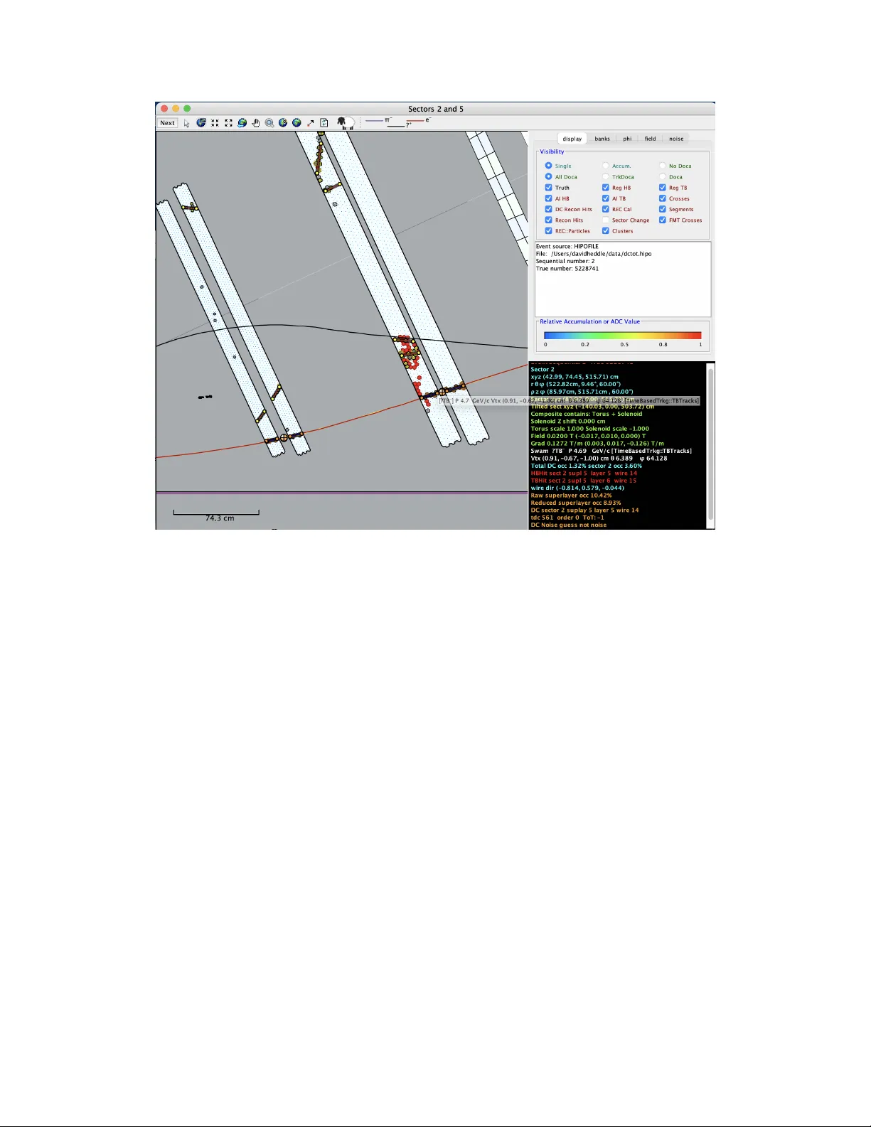
A Mo dular Multi-Do cumen t F ramew ork for Scien tific Visualization and Sim ulation in Ja v a D. Heddle Sc ho ol of Engineering and Computing Christopher Newp ort Univ ersit y david.heddle@cnu.edu F ebruary 25, 2026 Abstract This pap er presen ts the design and implemen tation of a mo dular m ulti-do cumen t interface (MDI) framework for scien tific visualization and simulation in the Jav a Virtual Mac hine (JVM) ecosystem. The framew ork emphasizes architectural separation betw een visualization la yers, sim ulation engines, and optional hardware-accelerated 3D rendering. 3D functionalit y is isolated in to a separate module to prev en t unnecessary dep endency coupling in 2D-only applications. W e describ e the core abstractions, threading model, sim ulation integration strategy , and dep endency isolation approach. A case study inv olving a real-time 3D gas expansion sim u- lation integrated with sync hronized 2D entrop y plotting demonstrates arc hitectural cohesion. The framework is publicly a v ailable via Mav en Central and targets long-lived scientific and engineering desktop applications. 1 In tro duction Scien tific and engineering desktop applications frequently require architectural prop erties distinct from those emphasized in con temp orary web and mobile developmen t. These include: • Deterministic rendering b eha vior • Long-running simulation support • Offline deploymen t capabilit y • Stabilit y across m ultiple Jav a releases • Minimal runtime dependency complexit y While modern UI to olkits often prioritize declarativ e in terfaces and rapid visual iteration, sci- en tific desktop systems typically prioritize robustness and long-term maintainabilit y . This pap er describ es the arc hitectural considerations underlying a mo dular Jav a-based framework designed sp ecifically for suc h applications. A cen tral principle of scientific computing is that insight emerges through structured visualiza- tion. The primary use case for MDI is the researc her emplo ying visualization to in terpret complex data, whether originating from sim ulation, mo deling, or real-time data acquisition. Applications 1 range from debugging complex detector systems to comm unicating exp erimental results to broader audiences. The design of MDI is informed b y classical principles of modular decomposition [ 4 ]. Rather than organizing functionalit y around graphical widgets alone, the framew ork decomposes resp onsibilities along architectural b oundaries: simulation, visualization, messaging, and application coordination. This separation enables scien tific applications to ev olve o ver time without entangling rendering logic with computational engines. 2 Arc hitectural Requiremen ts Through extended developmen t of researc h and instructional to ols, sev eral recurring architectural requiremen ts emerged: 2.1 Multi-Do cumen t Supp ort Scien tific applications often consist of multiple indep enden t y et coordinated views, including plots, sim ulation windows, diagnostic panels, and con trol interfaces. A m ulti-do cumen t architecture en- ables indep enden t lifecycle managemen t while preserving shared infrastructure. 2.2 Thread-Safe Visualization Sim ulations and data acquisition pro cesses t ypically execute on background threads. In contrast, the Ja v a Swing graphical toolkit emplo ys a single-threaded rendering mo del centered on the Ev ent Dispatc h Thread (EDT). All UI state mutations and repain t op erations must o ccur on the EDT to ensure correctness and prev ent race conditions. As discussed in the concurrency literature [ 2 ], improp er co ordination b et ween work er threads and the Ev ent Dispatc h Thread can lead to inconsistent state, deadlo cks, or repaint storms. Con- sequen tly , Swing-based systems require disciplined synchronization and strict thread confinement of UI up dates. The MDI framework adopts coalesced up date strategies and structured simulation stepping to ensure that bac kground computations interact safely with the EDT. By explicitly separating sim ulation execution from visualization sc heduling, the framew ork main tains resp onsiv eness while preserving thread safety . 2.3 Sim ulation In tegration A built-in step-based sim ulation engine supp orts: • Con trolled stepping • Cancellation supp ort • Reset ho oks • Co ordinated refresh sc heduling This ensures deterministic in teraction b et ween sim ulation logic and visualization lay ers. 2 2.4 Dep endency Isolation Hardw are-accelerated 3D rendering via JOGL [ 3 ] introduces nativ e and platform-sp ecific dep en- dencies. JOGL is a mature and widely used Op enGL binding for Ja v a. Native libraries in tro duce p oten tial compatibilit y risks across ev olving JDK releases and operating systems. T o preserv e ligh tw eigh t deplo ymen t for 2D-only applications, 3D functionalit y is separated in to an optional Ma ven mo dule. If 3D is not required, then only a dependency on the pure-Jav a core 2D framew ork is needed. This separation aligns with established principles of modular decomp osition [ 4 ]. 3 F ramew ork Design Desktop View View3D La yers La y ers Items Items Messaging Infrastructure Sim ulation Engine Optional 3D Extension (JOGL) Figure 1: Architectural ov erview of the MDI framew ork. The desktop manages multiple views, eac h comp osed of lay ers and items. A messaging infrastructure co ordinates state c hanges, while the sim ulation engine executes background computations. Optional 3D functionalit y is isolated in to a separate extension mo dule. Figure 1 summarizes the architectural structure of the framew ork. A t the highest level, an ap- plication consists of a desktop con tainer resp onsible for lifecycle managem en t and co ordination of m ultiple views. Eac h view is hierarchically comp osed of la yers, and eac h lay er contains in teractive items. This strict containmen t model clarifies rendering order, input routing, and state o wnership. The simulation engine op erates indep enden tly of the rendering hierarch y . Rather than in- teracting directly with view ob jects, simulation comp onen ts communicate through a ligh tw eigh t messaging infrastructure. This indirection reduces coupling b et w een computation and visualiza- tion, allowing views to subscribe selectively to state c hanges without requiring explicit references to sim ulation in ternals. Sim ulation execution o ccurs on background threads, while visualization up- dates are sc heduled onto the Even t Dispatc h Thread, enforcing an explicit concurrency b oundary within the architecture. Optional 3D functionality is isolated into a separate mo dule that integrates at the view lev el. As sho wn in Figure 1 , the 3D extension do es not alter the core desktop or messaging abstractions, 3 preserving a minimal dependency surface for 2D-only applications. This lay ered and mo dular structure reflects established principles of system decomp osition [ 4 ]. By constraining communication paths and enforcing explicit ownership b oundaries, the framew ork reduces architectural en trop y as applications grow in complexit y . 3.1 View Abstraction The core abstraction is the view , representing an indep enden t application windo w integrated into a shared desktop. The desktop ma y b e extended to virtual workspaces, allo wing large num b ers of views to co exist without ov erwhelming the physical displa y . 3.1.1 Anatom y of a View The optional comp onen ts of a view are illustrated in Figure 2 . This example, dra wn from the CLAS12 Even t Displa y [ 5 ] and originally developed using the predecessor framew ork bCNU, illus- trates the architectural requiremen ts that motiv ated the design of MDI. Views ma y function as quasi-indep endent sub-applications while retaining the ability to share data efficiently within a single JVM. Their main comp onen t is usually graphical, but can be purely text-based or controller-based. An MDI view pro vides structured supp ort for the follo wing elements: • Main conten t area. The primary rendering surface resp onsible for visualization. In this example it displa ys detector geometry , reconstructed particle trac ks, and asso ciated signal information. The conten t area is lay ered, allowing indep enden t rendering and interaction of geometric, reconstruction, and annotation elemen ts. • Extensible to olbar. A configurable to olbar supporting in teraction to ols such as zo oming, panning, and na vigation. T o ol configuration is declarativ e and indep enden t of the rendering implemen tation. • Con trol panel. An auxiliary in terface region used for configuration and state management. In this example, the tabbed panel in the upp er righ t controls visibility , accum ulation mo des, and displa y parameters. Suc h panels op erate indep endently of the rendering surface while comm unicating through a light w eigh t messaging mo del. • F eedbac k panel. A diagnostic region that pres en ts con textual system state. Here, the low er- righ t panel pro vides even t metadata and field v alues, up dated in response to user in teraction. • Ho v er feedbac k. T ransient con text-sensitiv e ov erla ys asso ciated with rendered items. This mec hanism provides detailed insp ection without cluttering the p ersisten t visualization. The co existence of these comp onents within a single view illustrates the need for clear sep- aration of rendering lay ers, input handling, simulation state, and user interface controls. These requiremen ts directly informed the mo dular abstractions adopted in the MDI framework. 4 Figure 2: A sample view. This view contains comp onen ts supp orted by the MDI framework including conten t, con trols, a to olbar, and con text-sensitive feedbac k. 3.2 La y ered Rendering Mo del Rendering is organized in to Z-ordered layers con taining interactiv e items . This enables: • Structured drawing separation • Selectiv e repainting • Clear input even t routing The user can define new la yers, reorder la yers (with a ca v eat discussed b elow), and toggle la y er visibilit y . A design constrain t is that t wo predefined lay ers are reserved: the connection lay er and the annotation la yer. These sp ecial lay ers cannot be mov ed or deleted. The connection la yer is alw a ys dra wn first, so that connections are drawn underneath all items. Annotations are dra wn last, so they alwa ys app ear on top. 3.3 Items So far w e ha v e seen that a MDI application is comprised of views, and views are comprised of la yers. The terminal abstraction in this hierarch y is the item . An item t ypically represents something “real”, like a nuclear ph ysics detector or a netw ork no de. Items can b e dragged, rotated, selected, resized, lo c ked, deleted, st yled, and edited. All such capabilities are av ailable but optional. There is a set of base classes that the user can extend: 5 • ConnectorItem. A connector b etw een t wo items • EllipseItem. An ov al shap ed item. • ImageItem. Displays an image. • LineItem. A line connecting t wo points. • P ointItem. A p oin t drawn with a glyph. • P olygonItem. A closed p olygon. • P olylineItem. An op en polygon. • RadArcItem. A pie-slice “wedge” shap e. • RectangleItem. A rectangular shap ed item. • T extItem. A multi-line text item. Complex items are created by extending one of the base classes. Figure 3 shows a v ery simple view with netw ork no des that extend the base class RectangleItem, adding the ability to display an SVG icon and to draw a string (the device name) underneath the icon. Figure 3: An example of a view with user-defined items. The net work no des extend the base class RectangleItem, from which they inherit a ric h set of capabilities including dragging, editing, resp onding to to olbar to ols, reordering and more. 3.4 Ev en t Co ordination A ligh tw eigh t messaging infrastructure co ordinates state changes across views without tigh t cou- pling. The messaging system enables loosely coupled in teraction b et w een views, con trol panels, and sim ulation comp onen ts. Messages are dispatc hed asynchronously and ma y b e filtered or scop ed to sp ecific views. This design av oids direct ob ject references across subsystems, reducing arc hitectural rigidit y and impro ving extensibility . 6 3.5 Sim ulation Engine The sim ulation engine op erates as a deterministic step lo op executed on background threads. After eac h simulation step, up date even ts are coalesced and dispatched to interested views. By decou- pling computation from rendering frequency , the framework av oids repaint storms and preserves in teractive responsiveness ev en during in tensive n umerical up dates. Sim ulation state transitions are explicit and observ able, enabling con trolled stepping, reset, and cancellation semantics. This structured model a voids ad ho c thread creation within views and cen tralizes concurrency managemen t. The user configures the engine threading through the timing parameters: • Refresh interv al: T arget interv al for p osting refresh ev ents to the EDT. • Progress interv al: T arget interv al for p osting progress “ping” even ts to the EDT. • Co operative yield: Rate limit for the simulation thread. It is not interpreted as “sleep this long each step”. It is a minimum in terv al betw een opp ortunities (which ma y comprise many sim ulation steps) for the simulation to yield CPU time. The engine nev er directly mutates Swing comp onents; instead, it p osts structured up date mes- sages to the EDT. 3.6 In tegrated Plotting MDI comes with sPlot, an integrated plotting pack age. Plots are in teractive, editable, and can b e p ersisted. An extensible collection of curve-fitting options are pro vided through a dep endency on the Apache Commons Math library[ 1 ]. Two examples are shown in Figure 4 . The plotting subsystem adheres to the same la yered and message-driven design as other views, allo wing plots to resp ond to simulation ev en ts without direct coupling to sim ulation internals. (a) A triple Gaussian fit. (b) A 2D Histogram Figure 4: The integrated sPlot pack age provides a v ariet y of plot t yp es and curve fitting options. 7 4 Optional 3D Extension Mo dule 3D functionality is implemen ted in a separate Ma v en artifact to a v oid coupling the core framework to JOGL. This design pro vides: • Reduced dep endency surface for 2D applications • Impro ved long-term JVM compatibility • Explicit architectural opt-in for Op enGL supp ort Both 2D and 3D views may coexist within a single application instance. 5 Case Study: Gas Expansion Sim ulation The 3D gas expansion example that trac ks the free expansion of 50,000 particles in a 3D view (see Figure 5 ) serv es as a compact integratin demonstration of the framew ork arc hitecture. The particle sim ulation executes on bac kground threads using a deterministic stepping model, while rendering is handled by the optional Op enGL extension mo dule. Simultaneously , a synchronized 2D plot tracks en tropy as a function of time, illustrating co ordinated multi-view updates. The demonstration in tegrates a real-time 3D particle simulation, synchronized 2D en trop y plot- ting, and interactiv e control panels for simulation managemen t. This example also demonstrates that the messaging infrastructure, sim ulation engine, and la y- ered rendering mo del operate cohesively across b oth 2D and 3D comp onen ts. Imp ortan tly , the 3D functionalit y is en tirely optional; the same arc hitectural structure supp orts purely 2D applications without mo dification. (a) Initial state: particles confined to a corner. (b) Final state: particles uniformly distributed. Figure 5: 3D gas expansion sim ulation with sync hronized entrop y plot. The 3D view renders particle motion while a 2D plot tracks en tropy o v er time. 6 Discussion The framework prioritizes stability and mo dularity o ver con temp orary UI trends. While alternativ es suc h as Ja v aFX and w eb-based framew orks offer modern interface paradigms, they in troduce trade- offs in dep endency fo otprin t, deploymen t complexity , or long-term ecosystem uncertaint y . 8 The design presented here emphasizes architectural clarity , dep endency isolation, and deter- ministic b eha vior suitable for scien tific and engineering contexts. The framework do es not attempt to comp ete with mo dern declarativ e UI systems in terms of visual styling or rapid protot yping workflo ws. Instead, it targets applications where long-term main tainability , deterministic execution, and tigh t in tegration b etw een computation and visualiza- tion are primary concerns. A potential limitation is that the framew ork remains within the Swing ecosystem, which, while stable, is no longer the fo cus of activ e feature expansion. Ho wev er, this stabilit y is view ed here as an asset for scien tific applications with m ulti-decade lifecycles. Unlik e framew orks that tigh tly couple rendering, simulation, and interface logic, MDI enforces explicit b oundaries b et w een these concerns. This separation improv es maintainabilit y , testabilit y , and long-term extensibility—qualities that are particularly imp ortan t for scientific softw are with m ulti-year lifecycles. 7 Av ailabilit y The framework is publicly av ailable: • GitHub: https://github.com/heddle/mdi • Ma ven Cen tral: io.github.heddle:mdi T o build and run the demo application from source: mvn clean package mvn exec:java -Dexec.mainClass="edu.cnu.mdi.demo.DemoApp" The 3D extension is also publicly av ailable: • GitHub: https://github.com/heddle/mdi- 3D • Ma ven Cen tral: io.github.heddle:mdi-3D T o build and run the 3D demo application from source: mvn clean package mvn exec:java -Dexec.mainClass="edu.cnu.mdi3D.app.DemoApp3D" Y ou can directly imp ort MDI and MDI-3D into your IDE as Mav en pro jects. MDI and MDI-3D are distributed under the MIT License. 8 Conclusion Long-liv ed scien tific desktop applications require arc hitectural discipline distinct from that empha- sized in rapidly evolving UI ecosystems. By prioritizing mo dularit y , thread safety , and dep endency isolation, the presen ted framew ork pro vides a stable foundation for visualization and sim ulation in the JVM environmen t. The framework is released as op en-source softw are under the MIT license and is intended to supp ort repro ducible scientific workflo ws. By pro viding architectural infrastructure rather than domain-sp ecific tooling, MDI offers a stable foundation for long-liv ed scien tific desktop applications requiring integrated visualization and simulation. The design principles describ ed here ma y also inform other mo dular JVM-based desktop systems. 9 References [1] Apac he Softw are F oundation. Apache Commons Math: The Apache Commons Mathematics Library. https://commons.apache.org/proper/commons- math/ , 2024. V ersion 3.6.1. [2] Brian Go etz, Tim Peierls, Josh ua Blo c h, Joseph Bowbeer, Da vid Holmes, and Doug Lea. Java Concurr ency in Pr actic e . Addison-W esley Professional, Boston, MA, 2006. [3] JogAmp Communit y. JOGL – Ja v a Bindings for Op enGL. https://jogamp.org/jogl/www/ , 2024. Accessed: 2026-02-21. [4] Da vid L. P arnas. On the criteria to b e used in dec omposing systems in to mo dules. Communi- c ations of the A CM , 15(12):1053–1058, 1972. [5] V Ziegler et al. The CLAS12 soft w are framew ork and ev en t reconstruction. Nucle ar Instruments and Metho ds in Physics R ese ar ch Se ction A , 960:163528, 2020. 10
Original Paper
Loading high-quality paper...
Comments & Academic Discussion
Loading comments...
Leave a Comment