Timing Recovery and Sequence Detection for Integrate-and-Fire Time Encoding Receivers
Recent advances in neuromorphic signal processing have introduced time encoding machines as a promising alternative to conventional uniform sampling for low-power communication receivers. In this paradigm, analog signals are converted into event timi…
Authors: Neil Irwin Bernardo
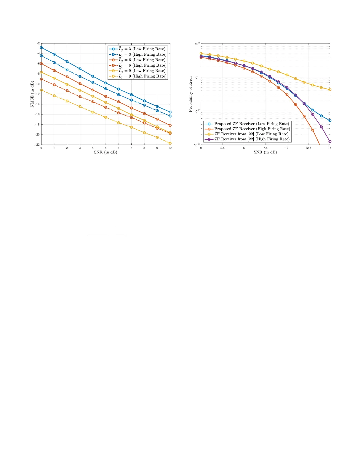
T iming Reco v ery and Sequence Detection for Inte grate-and-Fire T ime Encoding Recei vers Neil Irwin Bernardo Electrical and Electr onics Engineering Institute University of the Philippines Diliman Quezon City , Philippines neil.bernardo@eee.upd.edu.ph Abstract —Recent advances in neur omorphic signal pr ocess- ing have introduced time encoding machines as a promising alternativ e to con ventional unif orm sampling f or low-power communication recei vers. In this paradigm, analog signals are con verted into event timings by an integrate-and-fire circuit, allowing inf ormation to be r epresented thr ough spike times rather than amplitude samples. While event-dri ven sampling eliminates the need for a fixed-rate clock, receivers equipped with integrate- and-fire time encoding machines, called time encoding receivers , often assume perfect symbol synchronization, leaving the problem of symbol timing r ecovery unresolved. This paper presents a joint timing recovery and data detection framework for integrate-and- fire time encoding recei vers. The log-likelihood function is derived to capture the dependence between firing times, symbol timing offset, and transmitted sequence, leading to a maximum likelihood formulation for joint timing estimation and sequence detection. A practical two-stage recei ver is developed, consisting of a timing reco very algorithm follo wed by a zer o-for cing detector . Simulation results demonstrate accurate symbol timing offset estimation and impro ved symbol error rate performance compared to existing time encoding receiv ers. Index T erms —Time Encoding Machine, Sequence Detection, Timing Recovery , Integrate-and-fire Neuron. I . I N T RO D U C T I O N The time encoding machine (TEM) is a bio-inspired signal representation frame work that con verts an analog wa veform into a sequence of timing events [1]. Unlike con ventional sampling methods, where the signal is sampled at uniform intervals, the TEM encodes information in the time domain through the event times at which an internal state, e.g. ac- cumulated voltage, crosses a specified threshold [2]. Such ev ent-dri ven sampling eliminates the need for a fixed-rate clock during signal acquisition, allowing for asynchronous operation and reduced power consumption. Among various implementations of TEM, the integrate-and-fire TEM (IF- TEM) has recei ved particular attention due to its simplicity and close correspondence to the neuronal firing process [3]. Theoretical works ha ve established conditions for perfect recov ery of band-limited signals from IF firing times and demonstrated the stability of such encodings under bounded perturbations [4]. Recovery algorithms for IF-TEM hav e also been proposed to handle finite rate of innov ation (FRI) sig- nals, signals residing in shift-in v ariant (SI) spaces, and sparse signals [5–10]. In addition to these theoretical dev elopments, practical implementations of TEM ha ve been inv estigated in sev eral applications, including neuromorphic hardware, power- efficient data conv erters, image and video processing, and biomedical systems, where low-po wer operation and asyn- chronous ev ent-dri ven processing are adv antageous [11–19]. Recent works ha ve in vestigated the use of time encoding and neuromorphic signal processing principles in communication system design [20–22]. In [20], a fully-neuromorphic receiv er based on leaky integrate-and-fire neurons was sho wn to achieve competitiv e bit error rate performance with po wer consumption in the microw att range. Howe ver , this neuromorphic receiv er remains restricted to repetition-coded binary signaling and rectangular pulse shapes, with no demonstrated extensions to higher-order modulation formats or more general pulse de- signs. Building on this concept, another study [22] introduced a time encoding receiv er that supports multi-le vel signaling and Gaussian pulse shaping filters. The inter -symbol interference (ISI) arising from the pulse shaping filter is mitigated by using a zero-forcing (ZF) equalizer at the receiver . Similar to the neuromorphic receiver in [20], the time encoding receiver in [22] estimates the transmitted symbols from the number of firing ev ents per symbol period. Despite these advances, the problem of timing recovery in time-encoding receivers has not been explicitly addressed in the literature. Existing approaches typically assume perfect synchronization, i.e., that the receiver has prior knowledge of the symbol timing or that symbol boundaries are pre-aligned. Howe v er , in practice, even a small timing of fset can disrupt the correspondence between transmitted symbols and observ ed firing times. For instance, an incorrectly aligned observation window in [20, 22] may count spikes belonging to adjacent symbols, leading to erroneous spike counts and de graded detection performance. The nonlinear and asynchronous nature of the mapping from the input wav eform to the spike ev ents further complicates this task, rendering con ventional timing recov ery techniques ineffecti ve. This gap moti vates the de vel- opment of a framew ork for estimating the timing information and the transmitted symbols directly from the observed firing times. In this paper, we present a timing recov ery and sequence detection scheme for integrate-and-fire (IF) time encoding receiv ers. Specifically , we de velop a statistical framew ork that s (p) 0 , · · · , s (p) L p − 1 , s (d) 0 · · · , s (d) L d − 1 | {z } frame length L = L p + L d T ransmit Pulse Shaping Filter p ( t ) Sym b ol Timing Offset τ ϵ X ( t ) Z ( t ) ∼ G P 0 , N 0 2 δ ( τ ) Y ( t ) b 1 κ R Comparator ∆ Join t Timing Reco v ery & Sequence Detection T rigger Reset { t (p) k } , { t (d) k } ˆ s (d) 0 · · · , ˆ s (d) L d − 1 1 Compute τ (ML) ϵ 2 Compute { ˆ s (d) l } L d − 1 l =0 In tegrate-and-Fire Time Enco ding Receiver Fig. 1. System diagram of the proposed integrate-and-fire time encoding receiver . characterizes the relationship among firing times, timing of fset, and transmitted symbols, and formulate a maximum likelihood (ML) estimation problem for jointly recovering the timing offset and data sequence. T o achie ve computational tractability , we adopt a two-stage approach in which the timing offset is first estimated from the firing times induced by the pilot sequence, followed by data sequence detection using the firing times induced by the data symbols and the timing information estimated in the pre vious stage. The main contrib utions of this work are as follows: • W e derive the log-likelihood function for the joint esti- mation of the symbol timing and data sequence giv en the observed firing times and known pilot symbols. This for- mulation enables a unified statistical treatment of timing recov ery and data detection. • W e identify a necessary condition for the ML estimate of the timing offset and exploit this necessary condition to design a practical timing recov ery algorithm. • W e propose a sequence detection method based on a ZF receiv er that operates directly on the firing times instead of the firing count per symbol period. The proposed detector effecti vely mitigates ISI due to the pulse shaping filter and can operate at a low firing rate. • W e validate the proposed approaches through simulations, demonstrating robust timing estimation and improv ed symbol error rate (SER) performance compared to ex- isting time encoding receiv ers. I I . S Y S T E M A R C H I T E C T U R E W e consider the pilot-aided communication model for a time encoding receiver illustrated in Fig. 1. The transmit symbol sequence is divided into frames of length L . Each frame consists of a length- L p pilot sequence { s (p) l } L p − 1 l =0 and a length- L d data sequence { s (d) l } L d − 1 l =0 , where L d = L − L p . The pilot sequence is a fixed sequence and known to both recei ver and transmitter . Meanwhile, the symbols in the data sequence are drawn independently from an M -ary pulse amplitude modulation (P AM) constellation set A . The transmit symbol sequence is fed to a pulse shaping filter p ( t ) in order to produce the wa veform X ( t ) that lies in the shift-in v ariant (SI) space. More precisely , the signal X ( t ) can be written as X ( t ) = L p − 1 X l =0 s (p) l p ( t − lT ) + L d − 1 X l =0 s (d) l p ( t − ( l + L p ) T ) , where T is the symbol period. W e assume that the pulse shap- ing filter p ( t ) spans 2 L f + 1 symbol periods, with L f ∈ Z , and has negligible effect outside t ∈ [ − ( L f + 0 . 5) T , +( L f + 0 . 5) T ] . W e also assume that the guard interval of length L f is placed between frames to eliminate inter-frame interference. The channel introduces an unkno wn symbol timing offset τ ϵ ∈ [ − 0 . 5 T , +0 . 5 T ) to the transmitted signal X ( t ) and corrupts the delayed signal with additi ve white Gaussian noise (A WGN). The recei ved signal has the form Y ( t ) = X ( t − τ ϵ ) + Z ( t ) , (1) where Z ( t ) is modeled as a zero-mean white Gaussian process with autocorrelation function R Z ( τ ) = N 0 2 δ ( τ ) and N 0 is the noise spectral density (in W atts/Hz). At the time encoding recei ver , the continuous-time recei ved signal Y ( t ) is sampled using an IF-TEM characterized by parameters b , ∆ , and κ . The recei ved signal is first shifted by a constant bias b , chosen to ensure that Pr( Y ( t ) + b < 0) remains negligible. The biased signal is then scaled by κ and passed through an integrator , as shown in Fig. 1. The integrator output is continuously compared against a threshold ∆ . Each time the threshold is reached, a firing e vent occurs at time t k , which generates a spike and triggers the integrator to reset. The firing times { t k } obey the equilibrium condition ∆ = 1 κ Z t k t k − 1 Y ( t ) + b dt. (2) Here, we assume that the integrator is at rest at some time t = t 0 known to the recei ver and starts recording ev ents from this time onward. Because the firing times can grow without bound, it is often more practical to represent the signal by the intervals between successiv e firing times, known as time encodings . These time encodings T k = t k − t k − 1 are bounded by κ ∆ b + c max ≤ T k ≤ κ ∆ b − c max ∀ k , (3) where c max is the maximum amplitude of the IF-TEM input [4]. Nonetheless, the firing times can be recovered from the time encodings using t k = t 0 + P k k ′ =1 T k ′ . Suppose there are K + 1 firing times. Since a length- L frame contains pilot symbols and data symbols, we label the K + 1 firing times for the data symbol periods and pilot symbol periods as { t (p) k } K p k =0 and { t (d) k } K d k =1 , respectiv ely , where K = K p + K d . Specifically , t k is tagged as a pilot firing time t (p) k if t k ∈ [ − 0 . 5 T , ( L p − 0 . 5) T ) within a frame and is tagged as a data firing time t (d) k otherwise. Since the pilot sequence appears before the data sequence, we set t (d) 0 = t ( p ) K p . The reco very process at the time encoding receiv er in v olves two phases: (1) the timing r ecovery phase and (2) the data detection phase . During the timing recovery phase, the time encoding receiv er computes the maximum likelihood (ML) estimate of the channel-induced timing offset τ ϵ using the pilot firing times { t (p) k } K p k =0 . After computing ˆ τ (ML) ϵ , the re- ceiv er then identifies the length- L d data sequence sent by the transmitter from the data firing times { t (d) k } K d k =0 . The detailed operation of the time encoding receiver during these phases is described in the following section. I I I . T I M E E N C O D I N G R E C E I V E R A L G O R I T H M S A. Log-likelihood for J oint ML Estimation A key element in the estimation process is the log-likelihood function, which captures the statistical dependence between the observed firing times and the unknown parameters of interest. In the following proposition, we derive the log-likelihood function for the time encoding-based communication model presented in Section II. Proposition 1. Consider the observed firing time vector t = [ t 0 , · · · , t K ] T and the known pilot sequence vector s p = [ s (p) 0 , · · · , s (p) L p − 1 ] T available at the time encoding r eceiver . Let s d = [ s (d) 0 , · · · , s (d) L d − 1 ] T denote the data sequence vector . The log-likelihood function for jointly estimating s d and τ ϵ is ln L ( s d , τ ϵ | t , s p ) = C 0 ( t ) − T 1 2 y − P ( τ ϵ ) s p − G ( τ ϵ ) s d 2 , (4) wher e the k -th element of y ∈ R K × 1 is y k = κ · ∆ − b · [ t k − t k − 1 ] , (5) the k -th r ow and ( l + 1) -th column of P ( τ ϵ ) ∈ R K × L p is P ( τ ϵ ) k,l +1 = Z t k t k − 1 p ( t − lT − τ ϵ ) dt, (6) Algorithm 1: ML Timing Offset Estimation Input: N guess , { t (p) k } ˜ K p k =0 , { s (p) l } L p − 1 l =0 Output: ˆ τ (ML) ϵ 1 ˆ τ (ML) ϵ = NULL // Initialize / * Define the objective function in (13) * / 2 ML Ob j(x) = P ˜ K p k =1 ˜ y (p) k − P L p − 1 l =0 s (p) l ˜ P (x) k,l +1 2 2( t (p) k − t (p) k − 1 ) 3 for ℓ = 0 to N guess − 1 do 4 τ ( ℓ ) init = − 0 . 5 + ℓ N guess − 1 // ℓ -th initial guess / * Get root of (9) with initial guess τ ( ℓ ) init * / 5 τ ( ℓ ) candidate = result of applying Newton’ s method to (9) with τ ( ℓ ) init as initial guess. 6 if ML Ob j( ˆ τ (ML) ϵ ) > ML Ob j( ˆ τ ( ℓ ) candidate ) then 7 ˆ τ (ML) ϵ = ˆ τ ( ℓ ) candidate // update the estimate the k -th r ow and ( l + 1) -th column of G ( τ ϵ ) ∈ R K × L d is G ( τ ϵ ) k,l +1 = Z t k t k − 1 p ( t − ( L p + l ) T − τ ϵ ) dt, (7) T ∈ R K × K is a diagonal matrix whose k -th diagonal entry is [ T ] k,k = 1 t k − t k − 1 , and C 0 ( t ) is a term independent of the unknown parameters. Pr oof. See Appendix A. A joint maximum likelihood (ML) estimation of ( s d , τ ϵ ) can therefore be formulated as ˆ s (ML) d , ˆ τ (ML) ϵ = arg max s d ∈A L d τ ϵ ∈ [ − T 2 , + T 2 ] ln L ( s d , τ ϵ | t , s p ) , (8) which constitutes a non-con vex and NP-hard optimization problem. T o make the estimation process computationally tractable, we decompose it into two stages: (a) a timing recov ery phase, where the timing offset τ ϵ is estimated from the firing times using the pilot sequence, and (b) a data detection phase, where the data symbols are recovered using the estimated timing offset and the observed data firing times. B. T iming Recovery Phase Due to the absence of a fixed-rate clock in an asynchronous sampling system, it is not straightforward to identify the appropriate timing boundaries of a symbol period giv en the firing times. T o address this, the receiver estimates the timing offset τ ϵ from the pilot firing times and the known pilot symbol sequence. This subsection presents the algorithm for obtaining the ML estimate of τ ϵ . T o mitigate the effect of ISI from unknown data symbols, only the first ˜ L p = L p − L f pilot symbol periods are considered in the timing recovery phase. W e will call ˜ L p the effective pilot length . Let ˜ t p = [ t (p) 0 , · · · , t (p) ˜ K p ] T denote the vector of ˜ K p + 1 pilot firing times within the interval [ − 0 . 5 T , ( ˜ L p − 0 . 5) T ) . ln L τ ϵ | ˜ t p , s p ∂ τ ϵ τ ϵ = ˆ τ (ML) ϵ = ˜ K p X k =1 ˜ y (p) k − P L p − 1 l =0 s (p) l ˜ P ( τ ϵ ) k,l +1 T (p) k ! L p − 1 X l =0 s (p) l · ∂ ˜ P ( τ ϵ ) k,l +1 ∂ τ ϵ τ ϵ = ˆ τ (ML) ϵ = 0 . (9) By using this subset of pilot firing times, the log-likelihood function in (4) reduces to ln L τ ϵ | ˜ t p , s p = C 1 ( ˜ t p ) − ∥ ˜ T 1 2 p ˜ y p − ˜ P ( τ ϵ ) s p ∥ 2 , (10) where the k -th element of ˜ y p ∈ R ˜ K p × 1 is ˜ y (p) k = κ · ∆ − b · [ t (p) k − t (p) k − 1 ] , (11) the k -th row and ( l + 1) -th column of ˜ P ( τ ϵ ) ∈ R ˜ K p × L p is ˜ P ( τ ϵ ) k,l +1 = Z t (p) k t (p) k − 1 p ( t − lT − τ ϵ ) dt, (12) and ˜ T p ∈ R ˜ K p × ˜ K p is a diagonal matrix whose k -th diagonal element is [ ˜ T p ] k,k = 1 t (p) k − t (p) k − 1 . The ML estimate for τ ϵ can be formulated as ˆ τ (ML) ϵ = arg min τ ϵ ∈ [ − 0 . 5 T , 0 . 5 T ] ˜ K p X k =1 ˜ y (p) k − P L p − 1 l =0 s (p) l ˜ P ( τ ϵ ) k,l +1 2 2( t (p) k − t (p) k − 1 ) , (13) the objecti ve function in (13) can be interpreted as a weighted sum of squared errors, where each residual is weighted in- versely by the corresponding inter-spike interval duration. A necessary condition for ˆ τ (ML) ϵ is the first-order optimality condition gi ven in (9). Since the objectiv e in (13) is non- con ve x with respect to τ ϵ , multiple stationary points may exist. W e therefore employ Newton’ s method with several initial guesses on (9) to locate potential solutions and select the one yielding the minimum objecti ve value. The complete procedure is summarized in Algorithm 1. C. Data Detection Phase After estimating the timing offset τ ϵ , our next step is to recov er the data sequence vector s d from the K d + 1 data firing times t d = [ t (d) 0 , · · · , t (d) K d ] T . Previous approaches [20, 22] detect data symbols by counting the number of firing e v ents per symbol period and mapping this count to the corresponding symbol in the constellation. While this technique yields a coarse estimate of symbol amplitudes, it ignores the finer temporal variations within each symbol interval. T o improve detection accuracy , we use t d directly instead of the number of firing times per symbol period to generate the symbol sequence estimate. By substituting the ML timing estimate ˆ τ (ML) ϵ into the likelihood function in (4) and omitting constant terms that do not depend on s d , the ML estimation of s d becomes ˆ s (ML) d = arg min s d ∈A L d T 1 2 d y d − ¯ Gs d 2 , (14) where the k -th element of y d ∈ R K d × 1 is giv en by y (d) k = κ · ∆ − b · [ t (d) k − t (d) k − 1 ] − L p − 1 X l = L p − 1 − L f s (p) l Z t (d) k t (d) k − 1 p t − lT − ˆ τ (ML) ϵ dt, (15) the k -th row and ( l + 1) -th column of ¯ G ∈ R K d × L d is ¯ G ( ˆ τ (ML) ϵ ) k,l +1 = Z t (d) k t (d) k − 1 p t − ( L p + l ) T − ˆ τ (ML) ϵ dt, (16) and T d ∈ R K d × K d is a diagonal matrix whose k -th diagonal entry is [ T d ] k,k = 1 t (d) k − t (d) k − 1 . The final term in (15) accounts for interference contributions from the known pilot sequence. A variety of linear and nonlinear sequence detection tech- niques can be used to approximate the solution of the ML detection problem in (14) [23]. In this work, we adopt a suboptimal yet computationally ef ficient linear detector called the ZF receiv er . The ZF pre-estimate is given by ˜ s (ZF) d = ¯ G T T d ¯ G − 1 ¯ G T T d y d . (17) Subsequently , the elements of the ZF pre-estimate v ector ˜ s (ZF) d are mapped to the nearest symbol in the M -P AM constellation through hard decision decoding. The result of the hard decision decoding yields the length- L d sequence estimate ˆ s d = [ ˆ s (d) 0 , · · · , ˆ s (d) L d − 1 ] T . It is important to note that the ZF data sequence estimate deriv ed in this w ork fundamentally dif fers from the ZF detector presented in [22]. In our formulation, the ZF recei v er operates on the data firing time vector t d , which retains the fine temporal structure of the firing times. In contrast, the approach in [22] relies on the vector N = [ N 0 , · · · , N L d − 1 ] T , where each N l denotes the total number of firing events within the interval [( L p + l − 0 . 5) T , ( L p + l + 0 . 5) T ) . By lev eraging the precise timing information rather than aggregate spike counts, the proposed recei ver achie ves improved detection accuracy , particularly in low firing rate regimes. I V . N U M E R I C A L R E S U L T S In this section, we ev aluate the performance of the proposed timing recovery and data detection scheme for integrate-and- fire time encoding receiv ers under various system parameters. W e consider a pilot-aided transmission model with a total frame length of L = 100 symbols and a 4 -P AM modulation scheme with constellation A = {− 3 , − 1 , +1 , +3 } . The length- L p pilot sequence is composed of alternating symbols of +1 and − 1 , which f acilitates timing acquisition. W e also consider a Gaussian pulse shaping filter whose impulse response is p Gauss ( t ) = √ π a exp − π 2 t 2 a 2 , (18) 0 1 2 3 4 5 6 7 8 9 10 -22 -20 -18 -16 -14 -12 -10 -8 -6 -4 -2 Fig. 2. NMSE (in dB) vs. SNR (in dB) of the proposed timing recov ery for the integrate-and-fire time encoding receiver under dif ferent operating modes ( b = 1 . 50 and b = 4 . 50 ) and different effecti ve pilot lengths ( ˜ L p = 3 , ˜ L p = 6 , and ˜ L p = 9 ). where a serves as a shaping parameter that is inv ersely related to the product of the 3-dB bandwidth B 3dB and the symbol period T . More precisely , the parameter a is gi ven by a = 1 B 3dB · T r ln 2 2 . (19) For the experiments, we set T = 1 second and B 3dB = 0 . 5 Hz. The filter span of p ( t ) is set to 5 symbol periods ( L f = 2 ). W e implement the IF-TEM component of the integrate- and-fire time encoding receiver using the time encoding and decoding toolkit [24] from the Bionet Group of Columbia Univ ersity . The firing threshold and the inte grator constant are set to ∆ = 1 . 0 and κ = 0 . 1 , respectiv ely . T w o operating modes are considered: (a) a low firing rate mode with bias b = 1 . 50 and (b) a high firing rate mode with bias b = 4 . 50 . Using the transmitted signal X ( t ) described above and assuming a noiseless en vironment, the av erage spike rates for the low and high firing rate modes are approximately 15.34 and 44.91 firing ev ents per second, respecti vely . W e first e valuate the accuracy of the proposed timing recov ery algorithm based on the ML formulation in (13). W e assume that the symbol timing offset is drawn uniformly from the interval [ − 0 . 5 T , +0 . 5 T ] , and the performance metric considered is the normalized mean squared error (NMSE) between the ML estimate and true timing of fsets. The number of initial guesses in Algorithm 1 is set to N guess = 5 . Fig. 2 depicts the NMSE as a function of signal-to-noise ratio (SNR) in dB and under dif ferent ef fecti ve pilot lengths ˜ L p . It can be observed that the timing reco very performance improves as SNR increases, reflecting the fact that the observed firing times become more reliable at higher SNR le vels. Additionally , longer effecti ve pilot length leads to lower NMSE, indicating 0 2.5 5 7.5 10 12.5 15 10 -3 10 -2 10 -1 10 0 Fig. 3. Symbol Error Rate vs. SNR (in dB) of the proposed ZF-based sequence detection for the integrate-and-fire time encoding receiv er under different operating modes ( b = 1 . 50 and b = 4 . 50 ). Superimposed in the plot is the ZF receiver presented in [22]. that more pilot firing times pro vide richer temporal information that is relev ant for estimating the unknown timing of fset. The ef fect of the firing rate is also e vident: in the low firing rate mode ( b = 1 . 50 ), the NMSE remains slightly higher at lo w SNRs due to the sparser sampling of the input signal, whereas in the high firing rate mode ( b = 4 . 50 ), the denser spike occurrences allo w for more precise timing estimates across all SNR le vels. The gap between the NMSE of the low and high firing rate modes also increases with the pilot length, which can be attributed to the growing difference in the number of pilot firing times between the two modes as the effecti ve pilot length increases. After timing recovery , the data sequence s d is estimated from the observed data firing times t d using the ZF-based detection approach described in Section III-C. Fig. 3 compares the SER of our proposed ZF recei ver for inte grate-and-fire time encoding machine against the ZF receiv er presented in [22]. The results clearly show that the proposed sequence detection method outperforms the spike count-based ZF detector [22] for both operating modes. In fact, our proposed ZF receiver operating in the low firing rate mode has performance close to the spike count-based ZF receiver operating in the high firing rate mode from SNR = 0 dB to SNR = 12 dB. This can be attributed to the finer temporal resolution exploited by our proposed approach. V . C O N C L U S I O N This paper presented a statistical framework for timing recov ery and data detection in integrate-and-fire time encoding receiv ers. By modeling the relationship between firing times, timing offset, and transmitted symbols, we formulated a max- imum likelihood estimation problem that pro vides a unified treatment of symbol timing estimation and sequence detection tasks. A practical two-stage recei ver architecture was then de- veloped, consisting of an ML-based timing recovery followed by a zero-forcing-based sequence detection. Simulation results demonstrated that the proposed timing recovery algorithm achiev es accurate symbol timing estimates with reasonably short pilot sequences, while the proposed sequence detection method significantly improv es SER performance compared to existing spike count-based receiv ers. A C K N O W L E D G E M E N T S The author acknowledges the DOST -Science Education In- stitute (DOST -SEI) and the Engineering Research and De- velopment for T echnology (ERDT) Program for providing financial support for conference attendance, and the Of fice of the Chancellor of the University of the Philippines Diliman, through the Of fice of the V ice Chancellor for Research and Dev elopment, for funding support through the PhD Incentive A ward Grant 252509 YEAR 1. A P P E N D I X A P RO O F O F P RO P O S I T I O N 1 From (2), the firing ev ents satisfy κ · ∆ T k = 1 T k Z t k t k − 1 [ Y ( t ) + b ] dt = L d − 1 X l =0 s (d) l R t k t k − 1 p ( t − ( l + L p ) T − τ ϵ ) dt T k + b + L p − 1 X l =0 s (p) l R t k t k − 1 p ( t − lT − τ ϵ ) dt T k + R t k t k − 1 Z ( t ) dt T k | {z } Z k where Z k ∼ N 0 , N 0 2 · T k . The second line follows from the shift-in v ariant (SI) structure of X ( t ) . The last term is Gaussian due to the property of continuous time Gaussian processes. Since Z = [ Z 1 , · · · , Z K ] T ∼ N 0 , N 0 2 T , the conditional probability density function (PDF) of s (d) , τ ϵ giv en the firing times t and pilot sequence s (p) can be written as f s (d) , τ ϵ | t , s (p) = exp − T 1 2 ( y − P ( τ ϵ ) s (p) − G ( τ ϵ ) s (d) ) 2 N 0 ! ( π · N 0 ) K 2 Q K k =1 T − 1 / 2 k , where y , P ( τ ϵ ) , G ( τ ϵ ) , and T are defined in Proposition 1. The proof is completed by taking the natural logarithm of the conditional PDF and collecting all terms that do not depend on s (d) and τ ϵ in C 0 ( t ) . R E F E R E N C E S [1] H. C. T uckwell, Introduction to Theoretical Neurobiolo gy (Cambridge Studies in Mathematical Biology). Cambridge University Press, 1988. [2] M. Mi ´ sko wicz, Ed., Event-Based Control and Signal Pr ocessing . Boca Raton: CRC Press, 2015. [3] W . Gerstner, W . M. Kistler, R. Naud, and L. P aninski, Neuronal Dy- namics: F r om Single Neur ons to Networks and Models of Cognition . Cambridge, UK: Cambridge Uni versity Press, 2014. [4] A. A. Lazar, “T ime encoding with an integrate-and-fire neuron with a refractory period, ” Neurocomputing , vol. 58-60, pp. 53–58, 2004, Computational Neuroscience: Trends in Research 2004. [5] D. Gontier and M. V etterli, “Sampling based on timing: T ime encoding machines on shift-inv ariant subspaces, ” Applied and Computational Harmonic Analysis , vol. 36, no. 1, pp. 63–78, 2014. [6] R. Alexandru and P . L. Dragotti, “Time encoding and decoding of multidimensional signals with finite rate of innovation, ” in 2021 55th Asilomar Conference on Signals, Systems, and Computers , 2021, pp. 842–846. [7] A. J. Kamath and C. S. Seelamantula, “Differentiate-and-fire time- encoding of finite-rate-of-innovation signals, ” in ICASSP 2022 - 2022 IEEE International Conference on Acoustics, Speech and Signal Pr ocessing (ICASSP) , 2022, pp. 5637–5641. [8] H. Naaman, S. Mulleti, and Y . C. Eldar, “Fri-tem: Time encoding sampling of finite-rate-of-innov ation signals, ” IEEE T r ansactions on Signal Processing , vol. 70, pp. 2267–2279, 2022. [9] D. Florescu and A. Bhandari, “Time encoding of sparse signals with flexible filters, ” in 2023 International Confer ence on Sampling Theory and Applications (SampTA) , 2023, pp. 1–5. [10] A. J. Kamath and C. Sekhar Seelamantula, “Multichannel time- encoding of finite-rate-of-innovation signals, ” in ICASSP 2023 - 2023 IEEE International Conference on Acoustics, Speech and Signal Pr ocessing (ICASSP) , 2023, pp. 1–5. [11] A. A. Lazar and E. A. Pnevmatikakis, “V ideo time encoding ma- chines, ” IEEE Tr ansactions on Neural Networks , vol. 22, no. 3, pp. 461–473, 2011. [12] X. Kong, R. Matic, Z. Xu, V . Kuksh ya, P . Petre, and J. Jensen, “A time-encoding machine based high-speed analog-to-digital conv erter , ” IEEE Journal on Emerging and Selected T opics in Cir cuits and Systems , vol. 2, no. 3, pp. 552–563, 2012. [13] A. A. Lazar and Y . Zhou, “Reconstructing natural visual scenes from spike times, ” Pr oceedings of the IEEE , vol. 102, no. 10, pp. 1500– 1519, 2014. [14] D. Gutierrez-Galan, T . Schoepe, J. P . Dominguez-Morales, A. Jimenez-Fernandez, E. Chicca, and A. Linares-Barranco, “An e vent- based digital time dif ference encoder model implementation for neu- romorphic systems, ” IEEE T ransactions on Neural Networks and Learning Systems , vol. 33, no. 5, pp. 1959–1973, 2022. [15] N. Fu, H. Zhang, S. Y un, Z. W ei, and L. Qiao, “T ime-based finite- rate-of-innov ation sampling for variable-pulse-width signal, ” IEEE T ransactions on Instrumentation and Measur ement , vol. 73, pp. 1–9, 2024. [16] H. Naaman, D. Bilik, S. Sav ariego, M. Namer, and Y . C. Eldar, ECG- TEM: T ime-based sub-nyquist sampling for ECG signal r econstruction and hardwar e pr ototype , 2024. arXiv: 2405.13904 [eess.SP] . [17] H. Naaman, N. Irwin Bernardo, A. Cohen, and Y . C. Eldar , “T ime encoding quantization of bandlimited and finite-rate-of-innov ation signals, ” IEEE Access , vol. 13, pp. 184 745–184 761, 2025. [18] A. Arora and S. Mulleti, “A lo wrate variable-bias integrate-and-fire time encoding machine, ” in ICASSP 2025 - 2025 IEEE International Confer ence on Acoustics, Speech and Signal Pr ocessing (ICASSP) , 2025, pp. 1–5. [19] S. Mulleti, T . Zirtiloglu, A. T an, R. T . Y azicigil, and Y . C. Eldar, “Power -efficient sampling: T ow ards low-power analog-to-digital con- verters, ” IEEE Signal Pr ocessing Ma gazine , v ol. 42, no. 2, pp. 106– 125, 2025. [20] G. N. Katsaros and K. Nikitopoulos, “T oward fully neuromorphic receiv ers for ultra-power efficient communications, ” in 2025 IEEE 26th International W orkshop on Signal Pr ocessing and Artificial Intelligence for W ireless Communications (SP A WC) , 2025, pp. 1–5. [21] P . Biswas, M. D ¨ orpinghaus, and G. Fettweis, “If-tem-based detection for spike communications with rll encoding, ” IEEE Communications Letters , vol. 30, pp. 647–651, 2026. [22] N. I. Bernardo, “Symbol detection using an integrate-and-fire time encoding receiver, ” in 2025 IEEE W orkshop on Signal Pr ocessing Systems (SiPS) , 2025, pp. 1–5. [23] E. Larsson, “MIMO Detection Methods: How They W ork [Lecture Notes], ” IEEE Signal Pr ocessing Magazine , vol. 26, no. 3, pp. 91–95, 2009. [24] BioNet Research Group, TED: T empor al Event Data T oolbox for MA TLAB , https : / / github . com / bionet / ted . matlab, Accessed: 2025- 05-31, 2020.
Original Paper
Loading high-quality paper...
Comments & Academic Discussion
Loading comments...
Leave a Comment