Cooperative ISAC for Joint Localization and Velocity Estimation in Cell-Free MIMO Systems
In this paper, we explore a cooperative integrated sensing and communication (ISAC) framework that utilizes orthogonal frequency division multiplexing (OFDM) waveforms. Under the control of a central processing unit (CPU), multiple access points (APs…
Authors: Zihuan Wang, Vincent W. S. Wong, Robert Schober
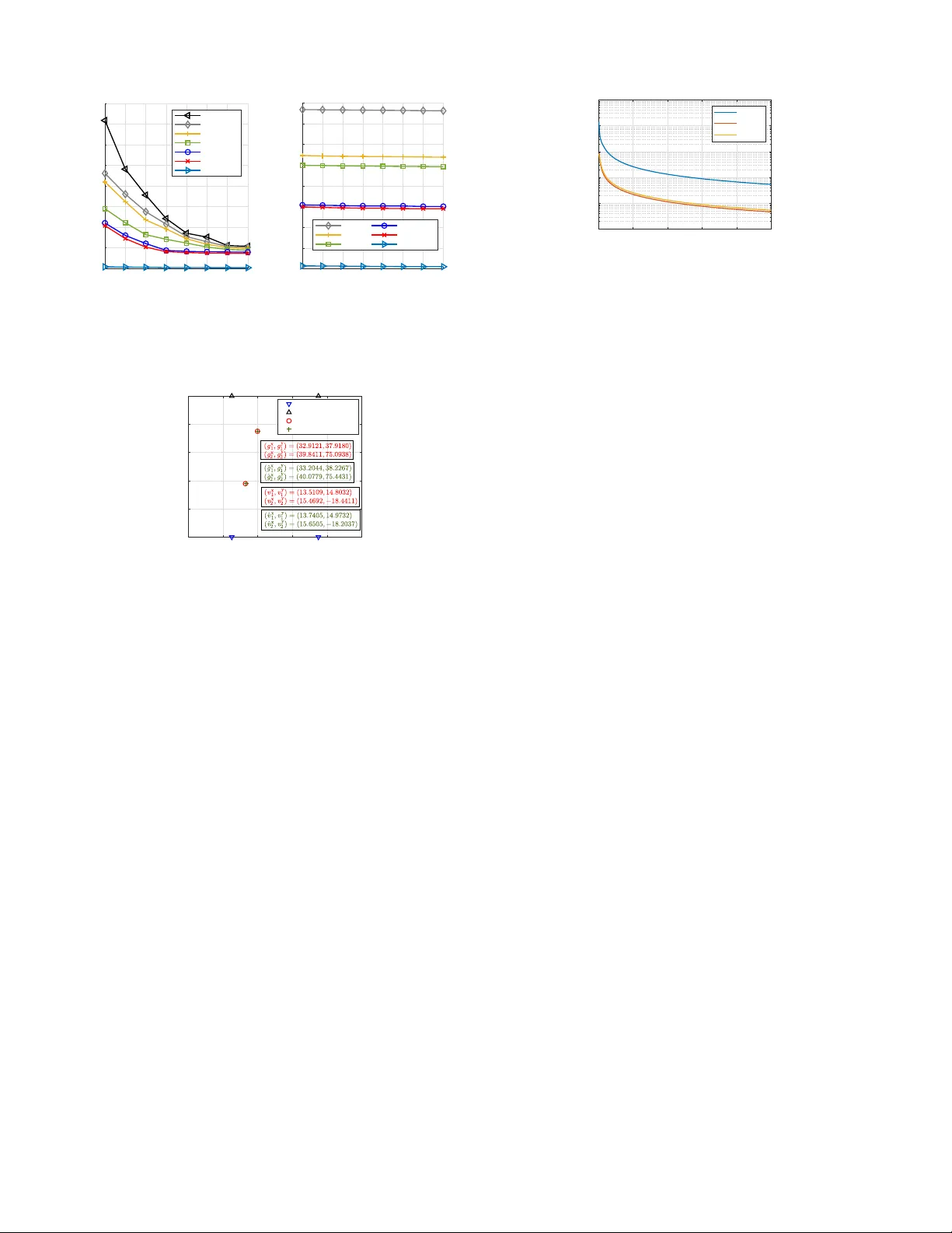
Cooperati v e ISA C for Joint Localiza tion and V elocity Es timation in Cell-Free MIMO S y stems Zihuan W ang, Member , IEEE, V incen t W .S. W ong, F e llow , IEEE, a nd Ro bert S chober , F ellow , IEEE Abstract —In t h is paper , we explore a cooperative integrated sensing and communication (ISA C) framewo rk that utili zes orthogonal frequency division multiplexing (OFDM) wa vef orms. Under th e cont rol of a central processing unit (CPU), multip le access points ( AP s) collaborativ ely perfo rm multistatic sensing while providing communication service in a cell-free multiple- input multipl e-output (M IMO) system. Achieving hi gh sensing accuracy requires the collection of global sensin g inform ation at the C P U , which can l ead to significant fronthaul signaling ov erhead due to the feedb ack of the sensing signals from each AP . T o t ackle this issue, we propose a collaborativ e p rocessing scheme in which the APs locally compress and q uantize the receiv ed sensing signals befo re forwarding them to the CPU . The CP U then aggre gates the infor mation from all APs to estimate th e location and velocity of the targe ts. W e develop a distributed vector -quanti zed variational autoencoder (D-VQV AE) to en able an end-t o-en d impl ementation of th is scheme. D-VQV AE consists of distributed encoders at the APs to locally en code th e recei ved sensing signals, codebooks for quan t i zing the encoded results, and a decoder at th e CPU for location and velocity estimation. It effectiv ely reduces the amount of data transmitted from each AP to the CPU while maintaini n g a hi gh sensing accuracy . W e employ a collaborativ e learning-assisted scheme to train D-VQV AE in an end-to-end manner . Simulation results show that th e proposed D-VQV AE network outp erf orms th e baselin e schemes in sen sing accuracy and reduces fronthaul signaling overhead by 99% when compared with th e centralized sensing approach. Index T erms —Cell-free MIMO, cooperativ e ISA C, localization and velocity estimation. I . I N T R O D U C T I O N The sixth gen eration (6 G) wireless networks aim to sup- port emerging services such as im mersiv e extended reality , intelligent tran sportation systems, and smart manu facturing, all Manuscript recei ved on Feb . 13, 2025; revi sed on Jul. 15, 2025; accept ed on Sept. 6, 2025. T he work of Zihuan W ang and V incent W ong was supported in part by the Gove rnment of Canada Innov ati on for Defenc e Excelle nce and Security (IDEaS) program and the Digita l Research Alliance of Canada (allia ncecan .ca). Robert Schober’ s work was supported by the Federal Min- istry for Research, T echnology and Space (BMFTR) in Germany in the program of “Souver ¨ an. Digita l. V ernetzt . ” joint projec t 6G-RIC (Project -ID 16KISK023), the Deutsche Forschungsgemeinsc haft (DFG , German Research Founda tion) under projects SFB 1483 (Project-ID 442419336, EmpkinS) and Horizon Europe Marie Skodo wska-Curi e Actions (MSCA)-UNITE under project 101129618. This paper has been published in part in the Pr oceedin gs of IEEE Inter- national Confer ence on Acoustics, Speec h, and Signal Pro cessing (ICASSP) , Apr . 2025 [1]. ( Correspond ing author: V ince nt W .S. W ong ) Zihuan W ang and V incent W .S . W ong are with the Department of Electric al and Computer Engineering, The Univ ersity of British Columbia, V ancouve r , Canada (e-mail: { zihuanwa ng, vincentw } @ec e.ubc.ca). Robert Schober is with th e Institute for Digit al Communications, Friedrich- Alex ander Univ ersity of Erlangen-Nurember g, E rlangen 91058, Germany (email: robert.schober@f au.de). Color versi ons of one or more of the figures in this paper are a va ilable online at https:/ /ieee xplore .ieee.org. of which d emand in creased spectrum usag e fo r bo th sensing and com munication . As co mmunica tio n systems transition to higher f requency band s, which are con ventionally used in radar systems, researcher s have been developing a lgorithms that en able spectrum sh a r ing between sensin g an d co mmu- nication systems. Incr easing attention is also bein g given to hardware sharing b e tween both systems in order to reduce the device size, weight, power co n sumption, and cost. Since the radio frequ ency (RF) f rontend arc h itectures emp loye d by radar sensing and wireless commun ica tion systems are similar , th e integration of these two fu nctionalities is feasible. This overlap in fr equency usage and h ardware design between radar an d commun ication systems has driven the emergenc e o f in tegra te d sensing and c o mmunica tio n ( ISA C). ISA C has been identified as a key use case for 6G and can benefit various application s, such as the Inte r net of Thing s (IoT) [2] and vehicular ne tworks [3 ]. It en ables wireless networks to simultan eously transmit inf ormation and re ceiv e sensing echoes throug h a u n ified infrastructure and shared resources, thu s improvin g bo th spectrum and energy effi- ciencies [4], [5]. Orthog onal frequency di vision multiplex- ing (OFDM) is a widely used wa veform in ISA C systems. OFDM wa veforms c an effectively combat frequen cy-selective fading and provide high d ata rates [6]. Mo reover , OFDM wa veforms exhibit Doppler toleran ce and do not suffer from range-Do ppler coup ling, which makes them su itable for radar sensing [7] , [8]. Unlike the conv entional OFDM rad ar systems, where the tran sm it sign als do no t carry useful informatio n, th e OFDM sign als used in ISAC systems contain modu lated data for comm unication, which introd uces d ifferent p hase shifts in the tran smit signals. These p hase shifts must b e con sid ered for sensing [9], [10]. By analyzing the reflected sensing signals, the ra n ge and velocity of the targets can b e estimated. The use of multiple-input mu ltiple-outpu t (MIMO) a r chitectures further pr ovides additional degrees of freedom (Do Fs) in the spatial do main, enab ling the extraction of angle, range, an d velocity info rmation of targets fro m the reflected sensing signals [11]–[ 1 3]. Howe ver , the conventional mo nostatic ISA C config uration with a single MIMO b a se station (BS) faces several limita- tions. On o ne hand , the com munication performa nce may be degraded du e to inter-cell in te r ference, an d users at the cell edge may experience poor service. On the other hand, relying on a single BS limits spatial diversity , which makes ac curate sensing in comp lex environments with multip le targets more challengin g . T o address these issues, cooperative ISAC ex- ploiting ce ll-free MIMO a rchitectures h as been pr o posed [14] – [17], wh ere multiple access points ( APs) are distributed across the coverage ar ea to jointly provide seamless communicatio n service and gather multivie w sensing o bservations. These APs are c onnected to a central proc e ssing unit (CPU), enabling effecti ve collaboration amon g the APs. Coo p erative ISA C can enh ance co mmunica tio n throu gh co ordinated multipoint transmission, providin g mor e reliable connection s and h igher throug hput. T he multistatic sensing enabled by cooperative ISA C offers wider sensing ran ges and captures multi view sensing information , lea ding to inc r eased sensing accu racy . A. Rela ted W ork o n I SAC Researchers have explored the use o f OFDM waveforms in ISA C systems. In [9], the OFDM wa veform is applied for range and velocity estimation witho ut com p romising the commun ication per formanc e. The sen sing chan nel frequ ency response is fir st estimated, wher e the co mmunication infor- mation is removed. A deep learning -based algo rithm is then applied to extract the ra nge and veloc ity inform a tion f rom the estimated freq u ency response. In [10], a super-resolution method is proposed for r ange and veloc ity estimation by exploiting th e translational in v ariance of the recei ved sensing signals in frequen cy an d time d omain. These stud ies fo c us on sin g le-input single-o utput (SISO) scenar io s, whereas in practice MIMO a r chitectures are wid ely employed at BSs to enhance the sp e c tral efficiency throug h beam forming , enab lin g the extraction of ang le, range, and velocity inf ormation from the reflected sensing signals [ 1 1]–[1 3]. In [ 11], sensing pa- rameter estima tio n u sing I SA C is studied. The multiple signal classification (MUSIC) algorith m is used f or angle estimation based on the sensing signals, fo llowed by the extraction of delay and Doppler s hifts using a two-dimen sional (2D) discrete Fourier transfo rm (DFT). In [12], the ang le, ra nge, and velocity of targets are sequen tially extracted from the received sensing signals using DFT . In [13], the sensing p arameters are jointly estimated thr ough spectral analy sis across the spa ce, frequen cy , and time d omains. Uplin k sensing is studied in [18], wher e the in itial delay is estimated and refin e d iter a ti vely , followed by angle and Doppler estimation . Given the estimated angle and rang e, th e target lo cations can be determined from the correspon ding geometric relationships. The aforem entioned works focus o n a sin g le BS for m onos- tatic sensing, which m ay resu lt in limited sensing perf o rmance due to restricted spatial diversity . Moreover, the velocity ob- tained based on th ese a pproach es is only th e r adial co mponen t deduced from Dopp ler shifts, while the tangential c ompon e nt of the velocity is u n av ailable. Thus, the c omplete v elocity vector of targets can not be o btained. T o overcom e these limitations, c ooperative ISA C has been pr oposed, utilizing geogra p hically distributed APs to gathe r multivie w sensing informa tio n. In [19 ], the angular infor mation of the targets in a cell-fr ee ISAC system is jointly estimated by distributed APs using deep neural ne twork s ( DNNs). In [20], an iterativ e angle estimation scheme is p roposed, where the a ngle is refined throug h iterative coarse and fine estimation procedure s. In [21], a cooper ati ve target localization scheme is proposed , where the angle and ran ge inf o rmation is first extracted from the received signals at each AP , followed by selecting a set of APs with high correlation s fo r cooperative localization. In [22], a max imum likelihood estimation based target local- ization scheme is proposed , where the APs collabo rativ ely estimate the locatio ns of the targets using the tran smit data payload from the uplink. In [23], a two-phase sch e me is propo sed for target localization by u sing cooper a tive I SAC. I n [24], ran ges are first estimated based on a two-dimension al fast Fourier transfo rm (2 D - FFT)-based a lgorithm. Then, the ta rget locations are estimated b ased on the rang e measurem ents. In [25], coo perative ISA C in cell-free MIM O systems is explored, where each AP emp loys a com pressiv e sensing ( CS)-based a l- gorithm to e stima te the ran ge, a n gle, a n d radial velo c ity of the targets. Then , the CPU d e te r mines th e targets’ lo cations and velocities by le veraging the geometric r e lationships. In [26], cooper a tive ISA C f or target sensing b a sed on sym bol-level informa tio n is in vestigated. The APs preprocess the collected symbols to extract th e state parameters and phase features of the target. The extracted infor mation is th en f used at the CPU for estima tin g the location and velocity of the target. In [2 7], collaborative mo tion reco gnition based on distributed I SA C is studied. A federated edge learning based sche m e is proposed for collaborative reco gnition wh ile pr e ser ving data priv acy . W e note that m ost of the existing works adopt a two-phase strategy for target lo calization an d velocity estimation, which can lead to error pro pagation an d potential per forman ce d egra- dation due to inaccu racies in the estimated ra n ge, angle, an d radial velocity . In [1], wh ich is the confer ence version of this paper, we pro posed a DNN consisting of conv olutional n eural network (CNN) layers to encode the reflected sensing ech oes and directly estimate th e location and velocity of the targets at the CPU. Th is appr oach bypasses the interme d iate step o f estimating the sensing parameters ( i. e., angle, r ange, radial velocity) and imp roves th e sensing perform ance. Howev er, it requires each AP to transmit high-d imensional sensing signals to the CPU for centralized processing, resu lting in significant fronth a u l signaling overhead. B. Rela ted W ork o n De ep Lea rning for Sig nal Compr e ssion Deep learnin g play s an importan t role in signal compr e s- sion in comm unication sy stems [28], which aims to reduce the signaling o verhead for sign al feedback from on e no de to another . One p opular deep learning based approach for signal com p ression and f eedback is the use of au toencode r architecture s [29] , [30 ]. I n these works, an encod er is utilized by the users to com press th e chann e l state inf ormation (CSI) and gen erate latent rep r esentations with lower dimensions. The co mpressed CSI is the n fed back to the BS, wh ere a de coder r econstructs th e orig inal CSI. Autoenco der-based CSI f eedback h as demonstrated significant improvement in reconstruc tion accuracy com pared with conventional CS-b a sed methods. Mor e over, variational auto encoder s (V AEs) have been prop osed to tackle sig nal compression [31] . V AEs model the latent space pro b abilistically b y learning a distribution over th e latent variables. This allows f or more r obust repre- sentations tha t can be beneficial in highly dynam ic or no isy en vironm ents. In V AE, the en coder comp resses the CSI by generating a distribution (typically Gaussian) over the latent space, fr om which samples are drawn and tran smitted to the BS. The d e coder then reco nstructs the CSI from these samples. More recently , vector qu antized variational autoen- coders (VQV AEs) have been utilized due to their ab ility to produ ce discrete latent c o des v ia codebo ok-based quan tiza- tion [3 2 ], [33]. In VQV AEs, the en coder output is mapped to the nearest co deboo k entry , resulting in compact ind ex- based rep resentations that are well suited f or qu antized digital feedback . Furth ermore, large found ation m odels ha ve b e en developed for wireless applications. These mod els lev erage transform er models with m ulti-head attention mech anisms to capture com p lex spatial and tem poral relation ships in wireless channels and aim to achieve g eneralization s across different tasks in wireless systems [34]. By pre-trainin g on large-scale data, large foundatio n mod e ls can ser ve as a univ ersal f eature extractor fo r v arious tasks in wireless systems. C. Mo tivations an d Contrib utions In this paper, we con sid er a co operative ISA C fr amew ork for multistatic sen sin g in cell-free MIMO systems. Under this framework, a set of distributed transmit APs send inf o rmation- carrying OFDM signals to the commun ication u sers. These signals also r each the sensin g targets within the area of interest, g enerating sen sing ech oes. These echo signals are then co llec te d b y a separ ate set of distributed rec ei ve APs. From the existing works, we observe that the r e are ty p ically two appro a ches fo r target localization and velo c ity estimation within the cooperative ISAC fram ework. The first approach is fully distributed sensing [2 4], where th e location and velocity of the targets are estimated in two pha ses. Each receive AP first indepen d ently estimates the angle, range, and rad ial veloc ity of each target, an d then forwards these pa r ameters to the CPU. Based on th e received par ameters, the CPU de te r mines the lo- cation and velocity of the targets. This ap proach incurs a small signaling overhead, as the estimated sensing par ameters can b e represented b y a small numb er of bits. Howev er , it may r esult in poor sensing ac c uracy due to estimation err or prop a gation. The seco nd app roach is centralized sensing [1 4], where the receive APs sen d the raw sensing signals to the CPU. The CPU estimates the location and velocity o f the targets ba sed on th e received sen sing signals. While this app roach can improve the sensing accuracy b y lev eraging global inform ation, it suffers from significant fronthaul signaling ov erhead f or transmitting the raw sensing signals. T o ad dress the aforem entioned issue, in this pap er , we propo se to split th e entire sen sing process between the receiv e APs and the CPU, which enables signal pre processing to be perfor med locally at the r eceiv e APs. Our pro p osed appr o ach reduces the amo unt o f data transm itted over the fron thaul links while ensuring tha t useful sen sing information is obtained by the CPU. The CPU can ef fectiv ely p erform target sensing by fusin g the informatio n o btained fro m all the receiv e APs, thereby providin g a high sensing accu racy . The m ain contri- butions of this paper are sum marized belo w: • T o en sure that the CPU can co llec t su fficiently accurate global sensing information while in curring a lo w sig- naling overhead over the fron thaul links, we d ev elop a collaborative processing scheme. In this scheme, signal prepro cessing is performed locally at each receiv e AP to compress the sensing signals and extra c t sensing-related features, followed by quantization. T he receive APs then send the q uantized results to the CPU. Thus, the amo unt of d ata tran smitted over the fr onthaul links is red uced. The CPU fuses the inf ormation o btained fr om all the receive A Ps to estimate th e locatio n and velocity of the targets. Comp a red w ith fully distributed and centralized sensing ap proache s, our proposed sche m e offers a tr a d e- off between signaling overhead an d sensing per forman ce. • W e prop ose a distributed vector-quantized variational autoenco der ( D-VQV AE) for collaborative pro cessing, which is re-architected from th e orig inal VQV AE and tailored fo r co operative ISA C in cell- free MIMO systems. The D-VQV AE network comprises distributed enco d ers and code b ooks at the r eceiv e APs and a decod er at the CPU. The receive APs encode the reflecte d sen sin g sig- nals locally th r ough their respective enc oders. Then, the encoded continuou s laten t representatio ns are quantized into discrete laten t feature vectors based on a code book, where only the indices of these vectors are transm itted to the CPU. Fin a lly , the CPU em ploys a decod er to estimate the loc a tion and velocity of the targets based on the informa tio n obtained from th e recei ve APs. • W e pr opose a c ollaborative learn ing-assisted f r amew ork for end -to-end training o f the D - VQV AE network, in which the receive A Ps and the CPU jo in tly optimize the encod e r s, cod e books, and decoder by exchanging intermediate featur e rep resentations a n d gradie n ts. Th e mean squ a red erro r ( MSE) b etween the n etwork estimates and grou nd truth serves as the e stimation loss to update the enco ders an d the d ecoder . Cod ebook en tries are re- fined via the expo nential m oving average (EMA) sch eme [35]. A commitmen t loss is employed to encou rage the encoded continuous representatio ns to rem ain close to their assigned co dew ords and en su res co n vergence. • W e conduct simulations and com pare our prop osed D- VQV AE network with fi ve baseline schemes, inclu ding monostatic sensing at a single BS propo sed in [13], a CS-based fully distributed sensing scheme [25] , a MUSIC-based distributed sensing extende d fr om [11], a CNN-based c entralized sensing scheme developed in our p reliminary work [1], and a d istributed variational autoenco der (D-V AE)-ba sed sch e me u sed for an ab lation study . W e also includ e the Cram ´ er-Rao lo wer boun d (CRLB) for location and velocity e stimation to serve as a perfor mance benchm ark. Simulation results demo nstrate the ben efits of cooper ati ve ISAC-assis ted target sensing over monostatic sensing. The resu lts also show the per- forman ce gains o f the propo sed D-VQV AE network over the ba seline schemes wh ile incu r ring a lo w fro nthaul signaling ov erhead . D. P aper Structur e a nd Notations The rest of this paper is organ ized as follows. T he system model for coop erativ e ISA C in cell-fr e e MIMO systems is T ransmit AP T ransmit AP Receive AP Receive AP CPU T a r get User User T arget T arg Fig. 1. Illustrat ion of cooperati v e ISA C for tar get sensing in a cell- free MIMO system. T he transmit APs send OFDM signals to multiple users for communicat ion, and these signals are reflec ted by the target s. The reflect ed sensing signals are coll ected by the recei ve APs. introdu c ed in Sectio n II. T he p roposed D-VQ V AE network is presented in Section III. The collabor ati ve learning-assisted training is described in Section IV. The perfor mance ev al- uation and comp a rison are provided in Section V. Finally , conclusion s are drawn in Section VI. Notations: W e use boldface lower case letters and boldface upper case letters to de n ote vector s and matrices/tenso r s, re- spectiv ely . ( · ) ∗ , ( · ) T , and ( · ) H are used to d e note the conjuga te, transpose, and con jugate transpose of a vector or m atrix, respectively . C N and R N denote the sets of N -dimension al vectors with comp lex entries and real entries, respectively . C N ( µ , Σ ) denotes the co mplex Gaussian distribution, where µ and Σ are the mean vector and covariance matrix , respec- ti vely . I N indicates an identity matrix of size N . a [ m : n ] denotes th e eleme n ts rangin g f rom the m -th element to the n - th element o f vector a . W e use j to den ote the imaginary unit which satisfies j 2 = − 1 . Re { ·} and I m {·} extract th e real part and imagin ary part of a complex num ber , respectively . E {·} deno tes the expected value o f a rand om variable. dia g( a ) conv erts a vector a to a diagonal m atrix with the elements of a on th e main d ia g onal. Finally , k · k 2 and k · k F denote th e n o rm of a vecto r and the Frobenius no rm of a matrix, respectively . I I . C O O P E R A T I V E I S AC I N C E L L - F R E E M I M O Consider a ce ll- free MIMO system with N transmit APs and M receive APs f or cooper a ti ve ISAC op e r ation. Each transmit AP is equ ip ped with N t antennas and each receive AP has M r antennas. All APs are connec ted to a CPU via fr onthaul links and they are fu lly synch r onized. T here are K single- antenna user s, which receive c ommunic a tio n signals from the transmit APs, and Q p oint-like targets to b e sensed in the are a of in terest. The tra nsmit APs send OFDM signals to all K users for comm unication. The se tr ansmit sign als also reach the targets within the ar ea of interest, gene r ating sensing echo e s which ar e co llected by the receiv e APs. The system mo del is shown in Fig. 1. Considering a 2D (x , y) coordin a te system, we defin e t n = ( t x n , t y n ) ∈ R 2 , n = 1 , . . . , N , as the location vector of the n -th transmit AP . Similarly , let r m = ( r x m , r y m ) ∈ R 2 , m = 1 , . . . , M , den ote the location vector o f the m -th receive AP . W e aim to estimate the unknown locations g q = ( g x q , g y q ) ∈ R 2 of the targets and their associated velocities ߠ ߴ Transmit ULA Receive ULA Target ߠ ߴ x y (a) ߠ ߴ Target Transmit ULA Receive ULA ߠ ߴ x y (b) Fig. 2. AoD θ and AoA ϑ with respect to (w . r.t .) a point-lik e target. T wo dif ferent orientat ions of the transmit and recei ve ULAs are shown in (a) and (b). In (a), the transmit and recei v e ULAs are aligned in opposit e directions. In (b), the transmit and recei ve ULAs are oriented with a phase shift between 90 ◦ and 180 ◦ relati ve to each other . along the x - and y -axes, i.e., v q = ( v x q , v y q ) ∈ R 2 for q = 1 , . . . , Q . W e d efine g = [ g T 1 · · · g T Q ] T ∈ R 2 Q and v = [ v T 1 · · · v T Q ] T ∈ R 2 Q . Let ψ = [ g T v T ] T ∈ R 4 Q collect the lo cation and veloc ity vectors of all targets in th e area o f interest, which n eeds to b e estimated by the CPU. The transmit and receive APs are equip p ed with un iform linear ar rays (ULAs). T he transmit an d receive b eam steering vectors are respectively given by a t ( θ ) = 1 √ N t 1 e − j 2 π d t /λ c cos θ · · · e − j 2 π ( N t − 1) d t /λ c cos θ T , (1) a r ( ϑ ) = 1 √ M r 1 e − j 2 π d r /λ c cos ϑ · · · e − j 2 π ( M r − 1) d r /λ c cos ϑ T , (2) where θ and ϑ denote th e ang le of d eparture (AoD) and angle of arriv al ( AoA), r espectiv ely . The defin itions of AoD and Ao A are illustrated in Fig. 2 , where two different ar ray orientation s of th e transmit and receive ULAs are pr esented. W e assum e that the orientations of the transmit and re ceiv e ULAs are kn own by the CPU. Moreover, d t and d r denote the tran smit antenna sp a cing and r eceiv e antenn a spacing, respectively . λ c = c/f c represents the wa velength, where c denotes the spe ed of light and f c is the carrier f r equency . A. Sig nal Mod el Let N s and ∆ f denote th e num ber of subcarrier s and the subcarrier spacing, respec tively . The OFDM symbol duratio n is given b y ∆ T = 1 / ∆ f + T p , wher e T p is the duration of the cyclic prefix. Let s i [ t ] = ( s i, 1 [ t ] , . . . , s i,K [ t ]) ∈ C K denote the t -th tran smit vector for the K users on the i -th OFDM subca rrier , whe re i = 0 , . . . , N s − 1 , t = 1 , . . . , T s , and T s denotes the n umber of OFDM symbo ls. W e assume each element o f vector s i [ t ] has unit power and the transmit symbols are statistically in depende n t, i.e., E { s i [ t ] s H i [ t ] } = I K . Let x i,n [ t ] ∈ C N t denote the signal on the i - th sub carrier transmitted by th e n -th transmit AP during the t -th OFDM symbol interval. It can b e exp r essed as x i,n [ t ] = K X k =1 w i,n,k s i,k [ t ] = W i,n s i [ t ] , (3) where w i,n,k ∈ C N t is the p recoder for the k -th user assigned to the n -th tr a nsmit AP fo r transmission on the i - th subcarrier, and W i,n ∆ = [ w i,n, 1 · · · w i,n,K ] ∈ C N t × K . The transmit power of the n -th tra nsmit AP is giv en b y P N s − 1 i =0 k W n,i k 2 F . Let P deno te th e m aximum power at each transmit AP . W e have P N s − 1 i =0 k W n,i k 2 F ≤ P . The preco ded signals in (3) are then tran sformed in to time d omain signals via in verse d iscr ete Fourier tr ansform (IDFT) a nd a cyclic prefix o f period T p is inser ted to mitigate inter-symbo l interferen ce. The time domain signals are assigned to th e correspo nding transmit APs. After digital-to-analo g conv ersion and RF co n version, the RF signals ar e emitted with carrier frequen cy f c by the tran smit AP antennas. B. Commu nication Model Let h i,n,k ∈ C N t denote the commun ication chan nel vector b etween the n -th tran smit AP and the k - th user on the i -th subcarrier . W e stack the channels between the k -th user and all tra n smit APs on the i -th subcarrier as h i,k = [( h i, 1 ,k ) T · · · ( h i,N ,k ) T ] T ∈ C N N t . Similarly , by stacking the beamfor ming vectors f or the k -th u ser on the i - th subcar rier o f all tran smit APs, we obtain the bea mformin g vector for th e k - th u ser on the i -th subcarrier as w i,k = [ w T i, 1 ,k . . . w T i,N ,k ] T ∈ C N N t . After down-conversion, a n alog-to- digital con version, cyclic prefix removal, and DFT , the received signal at the k - th user on the i - th subcarrier dur in g the t -th OFDM symbol interval can be written as y (c) i,k [ t ] = N X n =1 ( h i,n,k ) H x i,n [ t ] + n i,k [ t ] (4) = ( h i,k ) H w i,k s i,k [ t ] | {z } Desired signal + K X l =1 ,l 6 = k ( h i,k ) H w i,l s i,l [ t ] | {z } Combined interference + n i,k [ t ] | {z } Noise , (5) where n i,k [ t ] ∼ C N (0 , σ 2 c ) is the received noise of the k -th user on the i -th subcar rier . Conventional MIMO beamform ing technique s, such as max imum ratio tr ansmission, zero -forcing , and minimum mean- square er ror (MMSE) beamf orming, c a n be em ployed for the d esign of w i,k . In p ractice, the chann el vector b etween ea c h transmit AP and each u ser can be estimated throug h uplink tr a ining. In this work, we assume that the CPU has p erfect knowledge o f the CSI and employs centralized MMSE beamfor ming 1 for the transmit APs to effecti vely mitigate m ultiuser interference. 1 Similar to [13], [25], we focus on tar get sensing gi ven a fixed trans- mit beamforming design. The assumption of perfect CSI and adoption of communicat ion-cent ric beamformers leads to a communicati on performance upper bound. Imperfec t CSI has minimal impact on sensing performance . Our proposed scheme can also be applied in combinatio n with other transmit beamforming algori thms and under imperfect CSI conditi ons. C. Sensin g Mo del The transmit signals in (3) are reflected by the targets within the area of interest and the reflected sen sing signals are collected by th e receive APs. Sim ilar to [12 ], [13], and [2 5], we assume that there is a line-of - sight (Lo S) pa th b etween each transmit/receive AP and each target 2 . After samp ling and DFT processing, the r eceiv ed sensing sig n al d u ring th e t -th OFDM symbol interval on the i - th subcarr ier at the m -th receiv e AP is gi ven by (6) sh own at th e b ottom of this page. In (6), β n,m,q ∼ C N (0 , χ 2 ) is a complex r eflection coefficient, which includes the effects due to small-scale pathloss and radar cross section of the q -th target [1 6]. PL( d n,m,q ) = α 0 ( d n,m,q /d 0 ) − ζ is th e large-scale LoS pathloss coefficient between th e n -th transmit AP and th e m -th receive AP v ia the q -th target, wher e α 0 is the path loss a t referen ce distance d 0 and ζ is th e pathloss exponent. d n,m,q = d n,q + d m,q is th e b istatic range measured from the n -th transmit AP , via th e q -th target, to th e m -th receive AP , where d n,q and d m,q are gi ven as follows: d n,q = k t n − g q k 2 , d m,q = k g q − r m k 2 . (7) θ n,q correspo n ds to the AoD of the q -th target at the n -th transmit AP . ϑ m,q denotes the AoA of the q - th target at th e m -th r eceiv e AP . z i,m [ t ] ∼ C N (0 , ξ 2 z I M r ) is the observed noise at the m -th receiv e AP on the i -th subca r rier during the t -th OFDM symbol interval. τ n,m,q and f D ,n,m,q are the bistatic delay and Dopp le r frequen cy shift associated with the n -th transmit AP and the m -th r eceiv e AP via the q - th target, respectively . Th ey are defined as follows: τ n,m,q = d n,m,q c , (8) f D ,n,m,q = ( v n,q + v m,q ) c f c , (9) where v n,q and v m,q are the radial velocities o f the q -th target w . r .t. the n - th transmit AP and the m -th rece ive AP , respectively . If we con sider the deployme n t shown in Fig. 2(a), where the transm it UL A and rece ive ULA a r e oriented with a 180 ◦ phase shift relativ e to each other , the radial velocities can be expressed as follows 3 : v n,q = − v x q cos( θ n,q ) + v y q sin( θ n,q ) , (10) v m,q = v x q cos( ϑ m,q ) − v y q sin( ϑ m,q ) . (11) W e note that th e received sensing signal in (6 ) contains in- formation ab out ang les (via the AoA s) , ran ges (via the delays), and r adial velocities (via the Dop pler fr e quency shifts). Our goal is to estimate th e location and velocity of the targets b y 2 W e assume the contri butio ns of the multipath components are s mall. For simplicit y , we do not conside r their impact on sensing channe l modeling. Ho wev er , we e va luate the impact of multipa th components on the sensing performanc e via simulations in Section V -D. 3 When the transmit and recei ve UL As are deploye d with differe nt orienta - tions, the expressions for the radial vel ocity change accordingl y . y i,m [ t ] = N X n =1 Q X q =1 β n,m,q q PL( d n,m,q ) e − j 2 π ( iτ n,m,q ∆ f − tf D ,n,m,q ∆ T ) a r ( ϑ m,q ) a H t ( θ n,q ) | {z } ∆ = G i,n,m [ t ] x i,n [ t ] + z i,m [ t ] . (6) lev eraging th e sensing sign als obtained f rom m ultiple recei ve APs. Con ventional fully distributed sensing approaches [ 23]– [25] may suffer from perf ormance degradation due to erro rs in the parameters estimated by each receive A P . On the other hand, DNN-based centralized sensing schemes [1] can lear n to d irectly map the reflected sensing signa ls to the target’ s location and velo c ity , o ffering higher-accuracy estimates e ven in noisy en vironments. Howe ver , this approach incurs a large fronth a u l signaling overhead f o r f orwarding the sensing signals from the recei ve APs to the CPU. T o address this issue wh ile guaran tee ing high sensing accu racy , in the n ext section, we propo se a D - VQV AE network f or collabor ati ve proce ssing by the receive APs and the CPU. I I I . D - V Q V A E F O R C O O P E R A T I V E I S AC - A S S I S T E D L O C A L I Z AT I O N A N D V E L O C I T Y E S T I M A T I O N T o balance the sensing accuracy and fronthaul sign aling overhead in cooper ati ve ISA C systems, we propose a col- laborative processing scheme for target sen sing wh ere the overall task is split between the receive APs and the CPU. Instead of tran smitting h igh-dim ensional raw sensing signals to the CPU, each receive AP first perfor m s signal comp ression, sensing-related feature extraction, an d quantization locally . The qu a ntization r esults are then forwarded to the CPU. The informa tio n from all receive APs is fused at th e CPU for target localization and velocity estimation. T o facilitate effectiv e comp ression while extractin g essential informa tio n for target sensing, we le verage deep learning technique s. V AEs [36] are common ly used to reduc e th e dimensiona lity of input vector s or tensors b y ma pping them to con tinuous latent representations with r educed dimensio n s. VQV AEs [35] incorp orate a vector quantization mo d ule in to the V AE framework, enabling the en coding of inpu ts into dis- crete latent vector s suitable for e fficient digital tran smission. By further extendin g the VQV AE network, we pro pose a D- VQV AE network for collab orative processing by the receive APs and the CPU in an en d-to-en d m anner . Sp ecifically , each receive AP fir st en codes the r e c ei ved reflected sensing signals into contin uous latent f eatures, which are th en q uantized into a set of discrete latent vectors usin g a cod ebook . Th e co debook enables efficient comp ression by repr e sen ting the con tinuous features as a red uced set of discrete codew ords. E ach recei ve AP forwards o nly the indices of th ese codew ords to th e CPU. Based o n the indice s obtained f r om all receive APs, the CPU recovers the discrete laten t vector s an d uses a de coder to estimate the location an d velocity of th e targets. In the following, we provide the d e tails of th e enco der, the codeb ook- based vector quantization, and the deco der with in the D- VQV AE ne twork . A. En coder Design An enc o der is dep loyed at each r eceiv e AP f or signal compression and featur e extractio n. Given th e reflected sensing signals, sh own in (6), at each r e c ei ve AP , we fir st co ncatenate these signals across all the N s subcarriers and obtain matrix Y m [ t ] = [ y 0 ,m [ t ] · · · y N s − 1 ,m [ t ]] ∈ C M r × N s for the m - th receive AP . W e f u rther a ggregate th e sensing signals f or all T s OFDM sym bol intervals an d d enote the resulting three- dimensiona l (3D) tensor by Y m = [ Y m [1] · · · Y m [ T s ]] ∈ C M r × N s × T s . W e extract the real and imaginary p arts of Y m , which are given b y Re { Y m } and Im { Y m } , resp ectiv ely . Then, Re { Y m } an d Im { Y m } ar e n o rmalized and used as th e input to th e enc o der o f th e m - th r eceiv e AP . The reflected sensing signals con tain information across the space, freq uency , and time d omains, which is critical for ef fective feature extractio n. T o capture these jo int 3D domain featu res, we e m ploy 3 D CNNs in the enco der to d own- sample th e 3D signals and extract sensing -related feature s. Specifically , the real and imaginary parts of the concatenated reflected sensing signals, i.e., Re { Y m } and Im { Y m } , are regarded as two input channels for 3D convolution. At the m - th receive AP , where m = 1 , . . . , M , L cnn 3D CNN layers are employed to downsample th e input tensor . The kernel size is set to 4 with stride 2 an d pa d ding 1 to achiev e a downsampling rate of 2 . The trainable parame te r s of th e CNN layers of the e ncoder at the m -th receive AP are co llected in Φ cnn ,m . T he number o f ou tput chann els of the last layer is denoted by H . After downsampling, we em p loy a residu al network comp rising L res 3D CNN layer s with an addition al identity map ping to extract the sensing -related f e a tures. This residual n e twork enables us to learn deep space-freq uency- time domain cor relations without suffering from vanishing gradients, allowing the encoder to capture essen tial sensing- related features. The kernel size is set to 3 with pad ding 1 . W e deno te the param eters of the residual 3D CNN layers by Φ res ,m . W e use the rectified linear u nit (ReLU) as the activ ation f unction for all the CNN layers. Then , we obtain the en coded con tin uous latent feature s, ¯ Y m ∈ R H × ¯ M × ¯ N × ¯ T , where ¯ M , ¯ N , an d ¯ T are the re d uced dimension s of signals after encodin g . Let E m ( · ; Φ enc ,m ) denote the en coder at the m -th receive AP , where Φ enc ,m = { Φ cnn ,m , Φ res ,m } collects all parameters. The enco ded co n tinuous la ten t features can be expressed as ¯ Y m = E m ( Y m ; Φ enc ,m ) . (12) The arch itecture of the prop osed encoder is illustrated in the top-left part of Fig. 3. B. Cod ebook-B ased V ector Quantization Giv en the continu ous latent f eatures in (12), each receiv e AP the n employs a vector q uantization scheme to tr a nsform the continu ous featu r es into discrete laten t features. This trans- formation is a c hiev ed by quantizing th e en coded continuo us features in (12) based on a cod ebook . Only the indices of the selected cod ew ords are forwarded to the CPU, wh ich can effecti vely reduce the signaling overhead on the fronth aul link. In particular, let C m = [ c m, 1 · · · c m,N c ] ∈ R D × N c denote the codebook of the m -th receive AP for vecto r quan tization, which is shared with the CPU. The codeboo k con sists of N c codewords, w h ere eac h codeword c m,j has D dimensions. Giv en ¯ Y m , which co ntains enco ded fea tures of size ¯ M × ¯ N × ¯ T with each feature represented by a continuou s vector of size H , we aim to quantize each continuo us f e ature vector into a discrete latent vector based on th e codebook . Y m ∈ ℂ M r × N s × T s Re{ Y m } Im{ Y m } 3D CNN layers L cnn ¯ Y m ∈ ℝ H × ¯ M × ¯ N × ¯ T { { 3D CNN layers L res kernel , stride 2, padding 1 4 kernel 3, padding 1 Encoder Φ enc, m ¯ Y m ˜ Y m ∈ ℝ H × L Flatten Φ vq, m Z m ∈ ℝ D × L Codebook C m N c ¯ Z m ∈ ℝ D × L j * m ,1 , …, j * m , L Quantization ψ X ∈ ℂ NN t × N s × T s Re{ X } Im{ X } 3D CNN layers L t cnn { { 3D CNN layers L t res kernel , stride 2, padding 1 4 kernel 3, padding 1 Flatten C 1 Reshape { 3D CNN layers L c res kernel 3, padding 1 Flatten j * 1,1 ⋮ j * 1, L C M Reshape j * M ,1 ⋮ j * M , L M ¯ Z 1 ¯ Z M Z 1 Z M Z + + Decoder Φ dec + + + Fig. 3. The architec ture of the proposed D-VQV AE netw ork. Each recei ve AP uses an encoder to encode the obtained sensing signals locally , follo wed by vec tor quanti zation based on a codeboo k. The indi ces of the selected code wor ds are forwarded to the CPU. The CPU recove rs the discrete la tent feature vec tors based on the indices recei ved. Finally , the locati on and velo city of the targe ts are estimated by a decoder . In particular, ¯ Y m is first flattened into ˜ Y m ∈ R H × L , where L = ¯ M ¯ N ¯ T deno tes the n u mber of co ntinuou s featur e vectors. W e apply a lin ear projecto r with weight Φ vq ,m ∈ R D × H to transform ˜ Y m into Z m = [ z m, 1 · · · z m,L ] ∈ R D × L to match the dimen sionality to that o f the cod ebook. T h is transform ation can be expressed as follows: Z m = Φ vq ,m ˜ Y m . (13) For each vector z m,l , we use a quan tizer Q ( · ; C m ) to compare it with all th e codewords in codeboo k C m , and choo se the one which is n e arest to it in terms o f the Euclidea n d istance as the quantization output, ¯ Z m = [ ¯ z m, 1 · · · ¯ z m,L ] : ¯ Z m = Q ( Z m ; C m ) , where ¯ z m,l = c j ∗ m,l , (14) and j ∗ m,l = arg min 1 ≤ j ≤ N c k z m,l − c m,j k 2 2 . (15) Then, the m -th receive AP sends these indices j ∗ m,l , l = 1 , . . . , L , back to the CPU. The c odeboo k-based vector qu an- tization process is shown in the bo tto m-left part of Fig. 3. C. Dec oder Design On th e CPU s ide, after it has o btained th e ind ices fro m all the rec e i ve APs, the discr e te latent featu re matrix, ¯ Z m = [ ¯ z m, 1 · · · ¯ z m,L ] ∈ R D × L , m = 1 , . . . , M , can be recon - structed. The CPU u ses a decoder to esti mate the locatio n and velocity of the targets based on the d iscrete latent featu re matrix and the transm it signals in (3). In particular, we resha pe the discrete latent featu re matrix, ¯ Z m , of the m -th rec e ive AP into tensor ˆ Z m ∈ R D × ¯ M × ¯ N × ¯ T , which spans the spa ce-frequ ency-time domain. W e furth e r concatenate the f eature tensors of all th e receive APs along the first dimen sio n and obtain ˆ Z ∈ R DM × ¯ M × ¯ N × ¯ T . W e employ a residual network with L c res 3D CNN layers f or feature pr ocessing a cross the space-frequen cy-time domain. The c o rrespon d ing n etwork parameter s are co llec te d in ma- trix Φ c res . Fu rthermo r e, given the tr a nsmit sig nals in (3), which are av ailable at th e C PU, we co nstruct a 3D tensor X ∈ C N N t × N s × T s , which aggregates the transmit OFDM signals across the N transmit APs, N s subcarriers, and T s OFDM symb ol intervals. The real and imaginary pa rts of X are deno ted as Re { X } and Im { X } , respecti vely , which are regarded as two cha nnels f o r 3D convolution. Similar to the pr ocessing of the reflected sensin g signals, we employ L t cnn 3D CNN lay e rs to downsample the c o ncatenated tran smit signal X . The p arameters of the stacked 3D CNN layers ar e collected in m a trix Φ t cnn . After downsampling , we emp loy a residua l n etwork comprising L t res 3D CNN layers with an ad ditional identity mapping to f urther extract the featur es from the space- f requen cy-tim e d omain. T h e outputs of the residual network s are flattened. W e then app ly linear p rojectors with weig ht m atrices Φ c fc and Φ t fc to th e flattened vectors, respectively , to extract th e combined and hig h-level featur es. The outpu ts a r e concatenated and f ed into a fu lly connecte d layer with weight matrix Φ fc . Finally , we employ ano ther fully con nected lay er with weig ht matrix Φ out to gen erate the estimated locations ˆ g ∈ R 2 Q and velocities ˆ v ∈ R 2 Q for all the targets. Let D ( · ; Φ dec ) deno te the deco der at the CPU, where Φ dec = { Φ c res , Φ t cnn , Φ c fc , Φ t fc , Φ fc , Φ out } contain s the decoder param eters. The estimated r esults ca n b e expressed as ˆ ψ = D { ¯ Z m } m , X ; Φ dec , (16) where ˆ g = ˆ ψ [1 : 2 Q ] and ˆ v = ˆ ψ [2 Q + 1 : 4 Q ] are the estimated location and velo c ity of th e targets. For the q -th target, the estimated location and velocity ar e g i ven by ˆ g q = ˆ g [2( q − 1) + 1 : 2 q ] and ˆ v q = ˆ v [2 ( q − 1) + 1 : 2 q ] , respectively . The architecture of the deco der is shown in the rig ht pa r t of Fig. 3 . The workflow for th e co llaborative processing is illustrated in Fig. 4. D. Sig naling Overhea d Analysis In this subsectio n, we analy ze th e fronthau l signaling over- head in curred by o ur proposed sch eme and co mpare it with the fully d istributed and centralized sensing schemes. For the fu lly distributed sensing schem e, each receive AP transmits thr ee par ameters, i.e., angle, r a nge, and radial ve- locity , for each target to the CPU. Sup pose each par a meter is rep resented as a single-precision flo ating-po int number, requirin g 32 bits for enco ding. W ith Q targets, the to tal CPU Receive AP 1 Encode r En c o d e r !" #,$ Quantiz ation ! " ! Receive AP M Encode r En c o d e r !" #, $ Quantiz ation Q u a n ti z a t i o n ! " ! # $%& Decoder !,! " , … , !,# " , É , $, # " % & ' Fig. 4. Each AP encod es the reflected sensing signals local ly through its encode r , then quantiz es the encode d feature using a codeb ook. The CPU estimate s the loca tion and veloci ty of the tar gets through a decode r . fronth a u l signaling overhead for e a ch receive AP is equal to 96 Q bits, which scales linearly with the nu mber of targets. If the par ameter update freq uency is f updates per secon d, then the tran smission rate will b e equa l to 96 Qf bits per second (bit/s). Howe ver , as we mentioned earlier, th is ap proach may suffer fr om e stimation error p ropagatio n and limited sensing accuracy , as each receive AP oper ates indepen d ently with out lev eraging sp a tial relatio n ships with other receive APs. On th e other h a nd, the ce ntralized sensing ap proach req u ires each receive AP to send the raw sen sing sign als, i.e. , Y m with d im ension M r × N s × T s , dir ectly to the CPU for joint processing. Note that Y m is a complex tensor . Assum ing that each element of the real an d imaginary p arts of Y m is re p resented by a 32 -b it floating-po int number , the total fronth a u l signaling overhead is g iv en by 6 4 M r N s T s bits. Giv en a sensing sign al upd ate frequ ency of f upd ates per second, the requ ir ed transmission rate is 64 M r N s T s f bit/s. In practice, achieving high sensing accuracy nece ssitates a large number of antennas, subc a rriers, and OFDM symbols, m aking Y m typically very high- d imensional. This results in sub stan tial fronth a u l signaling overhead due to the transmission of Y m , leading to in c r eased latency and band width consump tion. Therefo re, wh ile ce n tralized sen sing can achieve high er sens- ing ac curacy b y leveraging glo bal sensing information, the significant overhead limits its scalab ility a nd ef ficiency . Our p roposed scheme p r ovides a trade-off between the fully distributed and cen tr alized sensing approach es. Instead of send in g hig h-dimen sional raw sensing signals, each receive AP p erform s local encoding o f the received sensing signals followed by cod ebook - based q uantization . Only the indices of the selected codewords are f orwarded to the CPU. Th is can significantly red uce the amoun t of informa tio n exchan ged over the f ronthau l links. Specifically , for a codeboo k of size N c , N b = log 2 N c bits are required to index each co dew ord. The frontha ul signaling overhead incu rred by each rece i ve AP is equal to N b L b its, wh ere L is the num ber of discrete feature vectors, which depends on the hyperparam eters of the D-VQV AE network. Similar to th e fully distributed and cen- tralized sensing approac h es, g iv en the upd ate frequency of f updates per seco nd, the req uired tran sm ission rate on the fron- thaul link is equ a l to N b Lf bit/s. W e n ote that the values of N b and L are significan tly smaller than the orig in al dimension s of the sen sin g signals. Hence, the signaling overhead co mpared with the centralized ap proach is significan tly red uced while the useful sensing informatio n necessary for accurate target localization and velocity estimation is p reserved. I V . C O L L A B O R AT I V E L E A R N I N G - A S S I S T E D T R A I N I N G O F T H E D - V Q V A E N E T W O R K T o facilitate offline training of the pr oposed D-VQV AE network, we apply a co llaborative learning framework to jointly train the receive AP-side networks (i.e., encode r and codebo ok) and the CPU-side n etwork (i.e., decoder ). Th e offline trainin g c o nsists of a forward propag ation phase fol- lowed by backpro pagation. The receive APs first en c o de their respective sensing sign als locally . Th en, after vector quantization , each rece ive AP forwards the indices to th e CPU. The CPU reco nstructs the d iscrete laten t featu re vectors based on the in dices an d estima te s th e locatio n an d veloc - ity of the targets through the d ecoder . Th is completes th e forward prop agation process. For backp ropagatio n, we no te that the qu antization operation is no n-differentiable, p r ev enting the g r adients from propag ating d ir ectly thr ough the discrete codebo ok-based quan tization step. T o ad d ress this issue, we apply the straigh t- throug h estimator [ 35], which allows the gradients to byp ass the non-d ifferentiab le step. In particular, the CPU calculates the loss g radients w .r .t. the deco der’ s inpu ts and directly propagates these grad ie n ts to the encoders at th e distributed receive APs. For offline tra ining, we construct a tr aining dataset D , which co ntains N d data samples. Each data sample con sists of a pair of inp uts and lab els. The transmit OFDM signals X and the reflected sen sin g signals Y m , m = 1 , . . . , M , serve as input, while th e true location and velocity of th e targets ψ are the lab els. W e deno te the trainin g dataset as D = { X ( d ) , Y ( d ) 1 , . . . , Y ( d ) M , ψ ( d ) } N d d =1 . The m -th receive AP only h as kn owledge of the reflected sensing signals that it has received, i.e., Y m , m = 1 , . . . , M . The transmit OFDM signal X is av ailable at th e CPU. Du ring tr a ining, we assume that the tru e location and velocity of the targets, ψ , are av ailable at the CPU. W e fur ther assume that th e index of the data samples in D is kn own by both th e receive A Ps and the CPU, and the sampling mechan ism is pr e defined by the CPU and shared with all the receiv e APs. Therefor e , the n etwork inputs are paired with the lab els during trainin g. The prop osed D- VQV AE network is trained using th e Adam optimize r [37]. During the offline training p h ase, the labels { ψ ( d ) } N d d =1 are normalized usin g max- min nor malization. The CPU records the maximum and minimum values fo r th is process. In th e online oper ation p hase, the estimated resu lts a re rescaled back to their nor mal values based on the recorded m aximum and minimum v alues. A. Upd ate of the Encoders, Codebooks, a nd Deco der The developed D-VQV AE network is co llaboratively tra ined between the CPU and the re c e i ve APs, wh ich en ables join t optimization of e ncoders, codebook s, and the deco der . In pa rticular, we employ the e stimation loss L est to update the d istributed enc oders and the decode r by minimiz in g the discrepancy b etween the gro und tr uth and the estimated values. Considering the MSE between them as the estimatio n loss, the estimation loss ca n b e calcu lated as fo llows: L est = R X r =1 k Ψ ( r ) − ˆ Ψ ( r ) k 2 2 , (17) where R denotes the total nu mber of training steps. Ψ ( r ) = { ψ ( r 1 ) , . . . , ψ ( r B ) } a n d ˆ Ψ ( r ) = { ˆ ψ ( r 1 ) , . . . , ˆ ψ ( r B ) } a r e batches of labels and ou tp uts in th e r -th training step, respec- ti vely , with B being the batch size. The c o deboo ks are upd a ted via the EMA scheme [35]. Denote c ( r ) m,j as the j -th co dew ord of the m -th receive AP in th e r -th training step. Let { z ( r ) m,N j 1 , . . . , z ( r ) m,N j r } d enote the set of continuo us feature vecto r s that have been assign ed to c ( r − 1) m,j , which is th e j -th codeword in th e ( r − 1) -th training step. Note that N j r is the total number of feature vectors assigned to th e j - th codeword. T h en, the EMA acc u mulators can be obtained as follows: L ( r ) m,j = γ L ( r − 1) m,j + (1 − γ ) N j r , (18) ˜ c ( r ) m,j = γ ˜ c ( r − 1) m,j + (1 − γ ) N j r X l = N j 1 z ( r ) m,l , (19) where L (0) m,j is initialized as zero fo r m = 1 , . . . , M and j = 1 , . . . , N c . Similarly , ˜ c (0) m,j is initialized a s a zero vector . The j -th cod ew ord a t the m -th AP is up dated a s: c ( r ) m,j = ˜ c ( r ) m,j L ( r ) m,j . (20) Moreover , no te that the quantiza tion process in troduces a mismatch between the outpu t of the enco der, z m,l , and the codeword. This mismatch can make it difficult fo r the en c oder to learn stable represen tations. T o address this issue, we ap p ly a com mitment loss L com to en courage the encoder outp ut to stay close to the cho sen codeword by penalizing d eviations: L com = ω R X r =1 L X l =1 M X m =1 z ( r ) m,l − s g[ c ( r ) j ∗ m,l ] 2 2 , (21) where ω is a hy p erparam e ter that scales the commitmen t lo ss. In (21), s g[ · ] d enotes the stop- gradient op erator [ 3 5], wh ich is defined as identity during forward com putation and has zero partial der ivati ves. Th is can effectiv ely restrict its operan d to remain co nstant with out upd ate durin g backpr opagation . The stop-grad ient oper ator is app lied to ea c h cod ew ord such th at only the outpu t of the enco der is b e in g upd a te d . Th is loss term ensures that the encod er comm its to prod ucing outp u ts that are close to the discrete c odeboo k an d help s the encoder learn to map the input consistently to the learn ed discrete latent space. B. T r aining Pr ocedur e In the following, we explain the collaborative lea rning- assisted offline training step by step. Th e overall training proced u re is summarized in Alg orithm 1 . Algorithm 1 Collaborative Learning- Assisted T raining 1: Input: Trainin g dataset D , learning rate of the Adam optimizer , batch size B , and total number of training epochs E . 2: Initialization. 3: f or training epoch e = 1 , . . . , E d o 4: fo r training step r = 1 , . . . , R do 5: Sample a batch of data samples from D . 6: fo r each receiv e AP in parallel d o 7: Local encoding of the r efl ected sensing signals. 8: Continuous feature quantization using the codebook. 9: Send t he discrete latent features ( 14) to the CPU . 10: Update its codeboo k locally . 11: end for 12: Decoding at the CP U. 13: Decoder update at the CPU. 14: The CPU sends the gradient of t he discrete latent features to the correspondin g receive AP s. 15: f or each receiv e AP in parallel do 16: Update its encoder locally . 17: end for 18: end for 19: end for 20: Output: Trained encoders, cod ebooks, and the decoder . Step 1 - Initialization ( line 2) . Th e CPU first initializes the parameters for the encode r, codeb ook, and decoder as { Φ (0) enc ,m } M m =1 , { C (0) m } M m =1 , a n d Φ (0) dec , r espectiv ely . Then , the CPU send s the initialized par a meters for the encode r s and codebo oks to the correspondin g r e c ei ve APs. Step 2 - F orward pr opagatio n o f the receive AP- side ne twork (lines 7 − 1 0) . In the r -th trainin g step, each receiv e AP draws a batch of inpu t data, Y ( r ) m = { Y ( r 1 ) m , . . . , Y ( r B ) m } , m = 1 , . . . , M . The m -th receive AP en codes the o b tained sensing sig n als lo cally and the encoded con tin uous featu res are given by ¯ Y ( r ) m = { ¯ Y ( r 1 ) m , . . . , ¯ Y ( r B ) m } , wh ich are fu r ther transform ed an d th en qua ntized in to discrete la ten t features ¯ Z ( r ) m = { ¯ Z ( r 1 ) m , . . . , ¯ Z ( r B ) m } based o n (13) and (14) , respec- ti vely . Then , each AP forwards the discr e te latent featur es to the CPU 4 and update its co d ebook loca lly based on (1 8 ) − (20 ). Step 3 - F orward p r op agation of the CPU-side network (line 12 ) . The CPU draws a b atch of its inp ut data, X ( r ) = { X ( r 1 ) , . . . , X ( r B ) } , and perfo r ms decoding based on th e dis- crete featu res obtained from th e receive APs a n d the samp led data X ( r ) . The batch of the decod er ou tput is given by ˆ Ψ ( r ) = { ˆ ψ ( r 1 ) , . . . , ˆ ψ ( r B ) } , where eac h element represen ts the estimated locations and velocities g iv en the r b -th inp ut in the batch, r b ∈ { r 1 , . . . , r B } . Step 4 - Backpr o pagation of the CPU-side network ( lines 13, 14) . Next, we up date th e network param eters by minim izing the estimation lo ss L est in (17) and the com mitment loss L com in (21) during backpro pagation. Given the estimated results ˆ Ψ ( r ) and the sampled lab els Ψ ( r ) = { ψ ( r 1 ) , . . . , ψ ( r B ) } , the gradients of all the layer s can be obtain ed by backpr opagation using the chain rule. The CPU u pdates the parameters of the decoder based on the Adam o ptimizer [37 ] and obtain s Φ ( r ) dec . When th e grad ient calculation proceeds to the first lay e r of 4 During training, the codebook at each recei ve AP is updat ed locall y and is not shared with the CPU in ev ery epoch. Therefore, the discret e latent feature s ha ve to be sent to the CPU for decoding. During online ex ecutio n, each recei ve AP can s imply transmit the indices in (15) to the CPU. Algorithm 2 Online Execution fo r T arget Sensing 1: Giv en Y m , m = 1 , . . . , M : 2: f or each receiv e AP in p arallel d o 3: Encode the reflected sensing signals and obtain the encode d continuous features as in (12). 4: Reshape the continuous features and apply a li near transfor- mation as in (13). 5: Quantize the features based on t he cod ebook as in (14). 6: Forward the indices (15) to the CPU. 7: end for 8: The CPU estimates the location and velo city of the targets through the decoder . 9: Output: Estimated location and veloc ity of the targets ˆ ψ . the deco der , the CPU sends the g radients of the d iscrete latent features (i.e., inputs to th e decod er) b ack to th e corresp o nding receive APs. Step 5 - Backpr opaga tion of the r eceive AP- side network (line 16) . W ith th e recei ved gradient of the discrete laten t features, each receive AP copies the obtained gradients to its encoder ou tput (i.e., continu ous latent featur e s) . Th e encoder is then updated thro ugh the Adam optimizer by each receive AP locally 5 . Steps 2 − 5 ar e iterated for R tra ining steps, and this com - pletes one training epoch. Let E denote the total training epochs. After training, we ca n obtain the trained D- VQV AE network with its optimized d ecoder param e te r s Φ ⋆ dec for th e CPU as well as encode r par ameters Φ ⋆ enc ,m and cod ebook C ⋆ m for the m -th receiv e AP , m = 1 , . . . , M . E ach re c ei ve AP then sends its trained cod e book to the CPU fo r onlin e execution. During online op e ration, giv en th e reflected sensing sign a ls in (6) , each recei ve AP first encod es the signals locally . After quantizing the encoded featur e s, each receive AP for wards the correspo n ding ind ic e s to the CPU. The CPU reco nstructs the discrete latent features and e stima tes the location and velocity of the targets thro u gh the trained deco der . The on line execution of the target sensing is su mmarized in Algo rithm 2. V . P E R F O R M A N C E E V A L UAT I O N In this section, we e valuate th e sensing perfor mance of the proposed D-VQV AE network thro ugh simulatio ns. W e consider a cell-f ree MIMO system with N = 2 transmit APs and M = 2 receiv e APs within a coverage area o f 100 × 1 00 m 2 . Conside r a 2D (x , y) coordin ate system 6 , the transmit APs are locate d at (25 , 0) and (75 , 0) . Th e receive APs a r e placed at (25 , 100) and (75 , 100 ) . Unless otherwise specified , we consid e r each AP has 1 6 antenna s, i.e. , N t = M r = 16 . The antenna spacing o f the ULA s is set to d t = d r = λ c / 2 . The transmit APs send OFDM symbols to K = 4 users for commu nication. Th e communication symbols are inde- penden tly d rawn from a 16 -quadr ature amplitud e modulation 5 W e assume each recei ve AP is equipped with a graphic s processing unit (GPU) to enable ef ficient local model updates and online inference, and has suf ficient memory to store both the encoder network and the codebook. 6 In this work, followi ng existing works [11]–[13], [25], we assume all APs and targets lie in a common horizontal plane and the APs employ UL As without elev ation div ersity . Howe ver , the propose d D-VQV AE networ k can be extended to 3D scenarios by expandi ng the network outputs to include the locat ion and velocit y coordinate s along the z -axis. 0 20 40 60 80 100 x 0 20 40 60 80 100 y Transmit AP Receive AP User Target Fig. 5. The topology co nsidered in simula tions. F or diffe rent cha nnel realiz ations, the locations of the APs are fixed, while the users and targets are randomly distrib uted in the 100 × 100 m 2 area. T ABLE I S Y S T E M S E T T I N G S Parameter Symbol V alue Carrier frequency f c 30 GHz Subcarrier spacing ∆ f 240 kHz Number of subcarriers N s 256 Number of OFDM symbols T s 256 Cyclic prefix duration T p 1 . 04 µ s Reference distance d 0 1 m Pathloss at the reference distanc e α 0 − 60 dB Pathloss exponent ζ 2 V a riance of the reflection coefficient χ 2 1 V a riance of the sensing noise ξ 2 z − 90 dBm ( 16 -QAM) constellation. A centralized MMSE beamfo rmer is utilized to precode the tra nsmit symbols. W e consider there are Q = 2 targets within this area. The u sers and targets are assumed to be random ly distributed in the area. T he system topolog y is illustrated in Fig. 5. Th e velocities of each target in x and y direction, i.e., v x q and v y q , are assumed to b e between − 20 m/s an d 20 m/s. W e list the p arameters of the O FDM wa veform and the chann el condition s in T able I. Based on this system setting, we generate 2 0,000 data samples with different channel realization s, where 16 ,000 o f them are used fo r offline training of the D-VQV AE n etwork, an d th e r emaining 4 ,000 data samples are used for online testing. The learning rate during trainin g is set to 10 − 4 . Note that the data samples are no rmalized during training. During o n line execution, the estimated results are rescaled ba c k to th eir normal values. The hyperp arameters are summarized in T ab le II. E ach receive AP side enc o der has ap proximate ly 1 . 2 millio n para m eters, and the comb ined encod er plu s cod ebook o ccupies ab out 5 M B of memory . On the CPU side, the decode r con sists of 206 million parameters, correspo nding to a model size of appro ximately 820 MB. A. Ba selines a nd Benchmark For perf ormance compar ison, we consider the f ollowing fi ve baseline schemes: • Mono static sen sin g b y a single BS [13]: This scheme assumes that the BS ope rates in full- duplex mode with perfect self-inter ference cancellation. Th e BS transmits OFDM sym bols to K users and recei ves sensing signals reflected by the targets. The BS pro cesses the reflected signals and estimates the angle, range, and r adial velocity of the p otential targets. For this schem e, we assume the BS is lo cated at (5 0 , 0) . T ABLE II H Y P E R PA R A M E T E R S O F D - V Q V A E Hyperparameters V a lue Encoder L cnn 2 L res 2 H 128 Codebook D 5 12 N c 32 Decoder L t cnn 2 L t res 2 L c res 1 • CS-based fully d istributed sensing scheme [25 ]: Giv en the sensing signals collected by the r e ceiv e APs in (6), this scheme first app lies a on e-dimension al (1D) CS algorith m to extract the delay inform ation for range estimation. Then, the angle and r adial velocity of each target ar e estimated b y each receive AP . The estimated sensing parameters are then sent to the CPU, based on which the location a n d velocity of each target are obtained. • MUSIC-based distributed sensing: This schem e extends the mo nostatic sensing alg orithm in [ 11] to the fully distributed sensing case. Each AP first estimates the angles of the targets via the MUSIC algo r ithm. Th en, range an d velocity are estimated throug h the 2D-DFT estimation method. The location and velocity of each target are d etermined by c o llecting the estimated sensing parameters. • CNN-based centralized sensing schem e [1]: I n this scheme, th e CPU directly estima te s the location and velocity of the ta rgets b a sed on the reflected sensing signals obta in ed from th e receiv e APs. A DNN architec- ture is dev eloped, which co nsists of two 3D CNN la y ers with a kernel size 5 for featu re extraction , followed b y max poo ling. The o utputs are then flatten e d and passed throug h three fully connected layers, each contain ing 256 neuron s, to generate the fina l estimates. • Distributed V AE (D - V AE)-based sch e me: This sch eme is developed fo r an ablation study , which does not in clude the vector quantizatio n modu le of the D- VQV AE network in Fig. 3. The encoder and d ecoder of the D-V AE network retain the same architectu re as their counterp arts in the D-VQV AE n etwork. The receive APs encod e th e ir respec- ti ve sensing signals loc a lly . Th en, the receive APs send the correspo nding enco ded continuo us latent features to the CPU, based o n wh ich the location a n d velocity o f each target are estimated at the CPU. W e f urther der i ve the CRLB for estimation o f ψ = [ g T v T ] T ∈ R 4 Q to serve as a perf ormance ben chmark. W e deno te β = { β n,m,q } n,m,q , wh ich collec ts the unkn own complex coefficients, and η = [ ψ T Re { β } T Im { β } T ] T ∈ R 4 Q +2 N M Q . Giv en the r eceiv ed sensing signa ls in (6) , we define the noiseless received sensing signal as ρ i,m [ t ] = N X n =1 G i,n,m [ t ] x i,n [ t ] ∈ C M r . (22) Let F ∈ R (4 Q +2 N M Q ) × (4 Q +2 N M Q ) denote the Fisher infor- mation matr ix (FIM) . The element in the a -th row and the b -th 5 10 15 20 25 30 35 40 45 P (dBm) 0 0.2 0.4 0.6 0.8 1 1.5 2 2.5 3 3.5 4 RMSE of location estimation (m) Monostatic CS MUSIC CNN D-VQVAE D-VAE Root CRLB (a) 5 10 15 20 25 30 35 40 45 P (dBm) 0 0.2 0.4 0.6 0.8 1 1.5 2 2.5 3 RMSE of velocity estimation (m/s) CS MUSIC CNN D-VQVAE D-VAE Root CRLB (b) Fig. 6. RMSE for (a) locat ion estimati on and (b) velocit y estimation versus the m aximum transmit power P . column of F , i.e., [ F ] a,b , is g i ven by [38] [ F ] a,b = Re ( 2 ξ 2 z M X m =1 N s − 1 X i =0 T s X t =1 ∂ ρ i,m [ t ] H ∂ η a ∂ ρ i,m [ t ] ∂ η b ) , (23) where η a ( η b ) d enotes the a -th ( b - th) entry of η , a, b = 1 , . . . , 4 Q + 2 N M Q . The FIM can be represented as F = F ψ ψ F ψ β F β ψ F β β , with F β ψ = F T ψ β . Th e partial derivati ves of ρ i,m [ t ] w .r .t. each entry of ψ and β are giv en in App endix A. Then, th e CRLB matrix fo r ψ can be o btained based on th e Schu r c o mplement as follows: CRLB ψ = F ψ ψ − F ψ β F − 1 β β F β ψ − 1 . ( 24) For the q -th target, the MSE lower bou n ds are given as: E ( ˆ g x q − g x q ) 2 ≥ CRLB ψ 2 q − 1 , 2 q − 1 , (25) E ( ˆ g y q − g y q ) 2 ≥ CRLB ψ 2 q, 2 q , (26) E ( ˆ v x q − v x q ) 2 ≥ CRLB ψ 2 Q +2 q − 1 , 2 Q +2 q − 1 , (27) E ( ˆ v y q − v y q ) 2 ≥ CRLB ψ 2 Q +2 q, 2 Q +2 q . (28) B. Se nsing P erformance W e ev aluate the sen sing performan ce of the co nsidered schemes, where the ro ot mean squared error ( RMSE) results for location and velocity estimation an d root CRLB a r e shown in Fig. 6. For the lo cation estimation results shown in Fig. 6(a), we includ e all baseline schemes for p erforman ce comp arison. In Fig . 6(b ), th e perfor m ance achieved by th e monostatic sensing scheme is no t included since only the radial velocity can b e estimated by a single BS. Th e com plete velocity vector cannot be obtained . In Fig. 6, the root CRLB shows that the theoretical lim its for location an d velocity estimation for P = 30 dBm are un der 0 . 1 m an d 0 . 1 m/s, respectively . It can be ob served th a t the RMSE for all schemes d ecreases with increasing transm it power and e ventually saturates to an error floor . Th is o ccurs because the available ban dwidth an d number of OFDM sy m bols limit the sensing resolu tion and achiev able p erforma nce, which causes th e RMSE to satur a te at a c ertain le vel r ather th an continuing to decrease with further increases in transmit power . The results also show that coop erativ e ISA C yields significan t sensing per formanc e improvement compared to mon ostatic sensing by a single BS. This is becau se the mon ostatic sensing scheme relies on a series of DFT op e rations and point-w ise d ivisions, m a king it susceptible to noise and less robust in n oisy environments. I n cooper a tive ISAC, signals collected from distributed receiv e APs p rovide multivie w in formation , which is mor e reliable than single-p oint obser vations. When comp a r ing DNN-b ased schemes (i.e., CNN, D- V AE, and D-VQV AE) with the fully distributed sen sing schemes (i.e., CS and MUSIC), the fol- lowing key advantages of deep learning techn iques can be identified. DNN-based schemes le verage the ab ility to jointly extract features from the sensing signals collecte d by mu ltiple distributed r eceiv e APs. This jo int feature extraction enab le s the network to capture complex sp a ce-frequ ency-time dom ain patterns, lead ing to mor e accurate and r obust target localiza- tion an d velocity estimation. Howe ver , for the fully distributed schemes, eac h receive AP processes the sensing signals ind e- penden tly , witho ut exploiting the spatial dependencies with other receiv e APs. M oreover , each rece ive AP estimates the sensing para m eters (i.e., angle, range, radial velocity) first before ob taining the locatio n and velocity inf ormation of the targets. By using DNN, th e inter mediate pa r ameter estimation stage can be bypassed and th e DNNs c an determine the location and velocity of the targets dir ectly ba sed on the received sensing sign als. T hus, any erro rs associated with the intermediate stage can b e av oided. Wh e n co mparing th e sensing perfor mance amon g the th ree D N N- based schemes, we observe th at the CNN-based app roach yields higher estimation errors than the other two, despite being a centralized sensing scheme. This limitatio n stems fro m the CNN’ s inability to fully captur e spac e -freque n cy-time featur e s, whe reas the more advanced DNN arch itectures can b etter h andle the comp lex 3D feature extractio n. W e also n otice th at the p roposed D-VQV AE network provides comp arable sensing per f ormance to the D- V AE network without quantiza tio n. Altho ugh quantization introdu c es distortion in the latent repr esentations, the collabo- rativ ely le a rned codeboo ks across receive APs still capture the essential sensing features, and the discrete cod ebook s yield an imp licit quantization regular ization effect. Co nsequently , despite the small qu antization erro r , the dev eloped D-VQV AE network ach iev es similar RMSE per formanc e as th e D- V AE network for both target location and velocity estimation, while significantly reducing th e fronthaul sign aling overhead. In Fig. 7, we illustrate the depe ndence of the sensing perfor mance on the numb er of targets Q , with the tran smit power P fixed at 30 dBm. Specifically , we plot the RMSE for both location and velocity estimation . It can be observed that, as the num ber of targets inc r eases, the conv entiona l ap p roaches (i.e., mo nostatic sensing a nd fully distributed sensin g schemes) experience significant pe r forman ce degradation . This is be- cause a larger number o f targets in troduces h igher co mplexity in separating individual sensing signa ls with in the space- frequen cy-time domain , leadin g to high er mutual interfer ence. On the o th er hand , th e DNN-based schemes co ntinue to exhibit satisfactory sensing p erforman ce w h en the n umber of ta rgets increases. This is be c ause th e CPU jointly processes the sensing signals or sensing-related fe a tures from all recei ve 1 2 3 4 5 6 7 8 Number of targets Q 0 0.5 1 1.5 2 2.5 3 3.5 4 RMSE of location estimation (m) Monostatic CS MUSIC CNN D-VQVAE D-VAE Root CRLB (a) 1 2 3 4 5 6 7 8 Number of targets Q 0 0.5 1 1.5 2 2.5 3 RMSE of velocity estimation (m/s) CS MUSIC CNN D-VQVAE D-VAE Root CRLB (b) Fig. 7. RMSE for (a) locat ion estimati on and (b) velocit y estimation versus the number of targets Q . 32 64 92 128 160 192 224 256 T s 0 0.5 1 1.5 2 2.5 RMSE of location estimation (m) Monostatic CS MUSIC CNN D-VQVAE D-VAE Root CRLB (a) 32 64 96 128 160 192 224 256 T s 0 1 2 3 4 5 6 RMSE of velocity estimation (m/s) CS MUSIC CNN D-VQVAE D-VAE Root CRLB (b) Fig. 8. RMSE for (a) locat ion estimati on and (b) velocit y estimation versus the number of OFDM symbols T s . APs, leveraging spatial depend encies across distributed APs to enha n ce target sensing accu r acy . More over, the DNN-ba sed schemes are able to learn the complex late n t features from both the transmit signals an d the reflected sen sing sig n als. By capturing the un derlying patterns and correlations within these signals, the DNN arc h itectures can effectively d istinguish the sensing signals of in dividual targets, ev en in the p r esence o f noise or significant signal overlap. As a result, they maintain robust accuracy and are better suited to han dle the inc reased complexity intro duced by a larger n umber o f targets. In Fig. 8, we investi gate h ow the num ber of OFDM sym bols, T s , affects th e sensing perf ormance . W e can o bserve from Fig . 8(a) that varying the value of T s does not sign ificantly impact the location e stima tio n performance . Th is is b ecause loc a tion estimation relies on the spa tial cor relations provid ed by th e sensing signals, which can be captu red even with a sm a ller number of OFDM sym bols. Incr easing T s mainly enhan ces the resolution for Dop pler estimation , which is critical for veloc ity estimation. As can be observed in Fig. 8 ( b), a smaller numb er of OFDM sy m bols m ay d egrade the velocity estimation per- forman ce due to reduced Do ppler freq uency resolution. How- ev er , ou r prop o sed D-VQV AE network demon strates g reater robustness ag ainst this effect. Th is imp roved robustness can be attributed to the D- VQV AE n etwork’ s ab ility to join tly extract time-dom a in featu res fro m the sensing sign als of distributed receive APs, th ereby m itigating the impact of a limited numbe r 4 8 12 16 20 24 28 32 M r 0 1 2 3 4 5 6 7 8 RMSE of location estimation (m) Monostatic CS MUSIC CNN D-VQVAE D-VAE Root CRLB (a) 4 8 12 16 20 24 28 32 M r 0 0.2 0.4 0.6 0.8 1 1.2 1.4 1.6 RMSE of velocity estimation (m/s) CS MUSIC CNN D-VQVAE D-VAE Root CRLB (b) Fig. 9. RMSE for (a) locat ion estimati on and (b) vel ocity estimation versus the number of antennas at the recei v e AP M r . 0 20 40 60 80 100 x 0 20 40 60 80 100 y Transmit AP Receive AP True locations Estimated locations Fig. 10. Comparison between the ground truth and the estimated loc ation and ve locity ( Q = 2 ). of OFDM sy m bols on velocity estimation. In Fig. 9, we study the impact o f the numb e r of anten n as at each receive AP on the sen sin g p erform a nce. The results indicate th at in creasing the num b er of antennas en hances localization perfo r mance. This impr ovement is du e to the fact that a larger number of antenn as of the receiv e AP increa ses the resolution in the spatial do main, allowing the system to better separate the sensing signals corresp o nding to different targets and differentiate between targets. On the other h and, the nu mber of rec e i ve antennas has little im p act on velocity estimation perfo rmance. This is b ecause velocity estimatio n primarily relies on the Doppler shift inf ormation, wh ich does not benefit sign ificantly from the in creased spatial resolu tio n provided by additio n al anten n as. In Fig. 10 , we v isu alize the results f or target localization and velocity estimation an d co mpare the estimated values with the grou n d truth. The results in Fig. 10 dem o nstrate that the propo sed D- VQ V AE network achieves a high localization ac- curacy , y ielding estimation er rors below 1 m in the con sidered cell-free MIMO system. Similarly , the estimated veloc ity o f the target is also shown to be close to th e g r ound truth, as can also be o bserved fr o m the figur e. Next, we study the conv ergence perfo rmance of the pr o- posed schemes in Fig. 1 1. W e evaluate the impact o f learning rate (denoted as “lr” in Fig. 11) on the convergence perfor- mance. Th e results indicate that the use of a large learning rate (e.g., 10 − 3 ) may not necessarily lead to convergence to a desirable trained result. On the other hand, a smaller learning 0 100 200 300 400 500 Epoch 10 -4 10 -3 10 -2 10 -1 10 0 10 1 Training Loss lr = 10 -3 lr = 10 -4 lr = 10 -5 Fig. 11. Training loss versus the epoch for differe nt learning rates. rate (e.g. , 1 0 − 4 or 10 − 5 ) en sures that the d ev eloped D-VQV AE network converges to a satisfactory solu tion. Furth ermore, the results ind icate that a learnin g rate of 10 − 4 achieves sligh tly lower training loss compar ed to that of 10 − 5 . Based on th ese observations, the lear n ing rate is set to 10 − 4 for the tra in ing of the D-VQV AE network. C. Sign aling Ove rhead a nd Online E xecution Runtime In th is subsection, we ana lyze the sign a ling overhead in- troduced in the fron thaul link for th e considered schem es. The analysis is b ased on the network param eters p rovided in T able I I. Ac c ording to the discussion in Section I II-D, the fully distributed sensing scheme requires 96 Q = 192 bits f o r each receive AP to forward the estimated sensing parameters to th e CPU v ia the fron thaul link. For centr alized sensing, the fronth a u l signaling overhead is significantly high er , which is giv en b y 2 × 32 × M r N s T s = 67 Mbit per u p date. In o ur pro posed D-VQV AE network, th e signaling overhead is r e duced b y downsampling th e o riginal sensing signals by a factor of 4 in each d imension. This process signifi- cantly reduces the n umber o f fea tu re vectors, resulting in L = ¯ M ¯ N ¯ T = 16 ,384. Each feature vector is then quan- tized using a codeb o ok, where each vector is indexed by its correspo n ding cod ew ord. In Fig. 12, we show the RMSE fo r location and velocity estimation fo r varying signaling cost on each fron thaul link. Note that the fr onthaul overhead d epends on the codebook size N c . The r esults demonstrate that a larger co deboo k reduc e s the estimation e rror, as increasin g the codebo ok size enab les m ore p recise quantization of the latent r e presentations, allowing the d iscrete laten t f eatures to better cap ture the usefu l inform ation f rom the sensing signals. It can be ob ser ved that the p r oposed D-VQV AE network achieves good performance when N c = 32 , corresp onding to a N b = 5 -bit cod ebook. Incre a sing N c further pr ovides small perfor mance improvements but may intro duce add itional complexity to the system. When N b = 5 , the fronth a ul signaling overhe a d is g iv en by N b L = 82 kb it. Compar e d with the ce ntralized sen sing scheme whic h incur s 67 Mbit of overhead, the p roposed scheme red uces the signaling overhead on the fron th aul link by 99 % . M eanwhile, the transmission from each receive AP to the CPU con tains essential sensing informa tio n, ensuring effecti ve target sensing. Then, in T able III, we e valuate the onlin e execution run time for the propo sed D-VQV AE network with batch size B = 20 . W e con d ucted th e simulations using a co mputing server with 30 60 90 120 Fronthaul overhead (kbit) 0.5 0.6 0.7 0.8 0.9 1 RMSE of location estimation (m) 0.5 0.6 0.7 0.8 0.9 1 RMSE of velocity estimation (m/s) Location estimation Velocity estimation N c = 32 Fig. 12. RMSE for location and veloc ity estimation versus the fronthaul ov erhead. T ABLE III O N L I N E E X E C U T I O N R U N T I M E Settings Encoder Quantization Decoder N t = N r = 16 N s = T s = 256 6 . 75 ms 2 . 51 ms 23 . 89 ms N t = N r = 8 N s = T s = 256 2 . 25 ms 1 . 34 ms 5 . 03 ms N t = N r = 8 N s = T s = 128 1 . 59 ms 1 . 15 ms 2 . 42 ms an In tel Core i7-107 00 @ 3 .80 GHz CPU and an NVIDIA GeForce R TX 3070 GPU. W e show the com putational time for the encoder, co debook -based quantiza tion, and decoder under various system configura tio ns. The results in T able III show that the enco ding and co deboo k -based quan tization can be co mpleted in on ly a few m illiseconds, demon strating the minimal com putational lo ad on each re c ei ve AP and the overall efficiency of our mo del. D. Effect of Mu ltipath Components In th is subsection, we evaluate the impact of multipath compon ents on sensin g perfo rmance. In add ition to the LoS sensing chann el G i,n,m [ t ] shown in (6 ), we also include the non-L o S com ponent caused b y S clutter scatterer s, wh ich is modeled as: ˜ G i,n,m [ t ] = S X s =1 ˜ β n,m,s q PL( ˜ d n,m,s ) × e − j 2 π ( i ˜ τ n,m,s ∆ f − t ˜ f D ,n,m,s ∆ T ) a r ( ˜ ϑ m,s ) a H t ( ˜ θ n,s ) , (2 9) where ˜ β n,m,s ∼ C N (0 , ˜ χ 2 ) denotes the comp lex reflection coefficient o f th e s -th n on-LoS scattering path between the n -th transmit AP and the m -th receive AP . ˜ d n,m,s , ˜ τ n,m,s , and ˜ f D ,n,m,s denote the experienced d istan ce, delay , and Doppler shift throu gh the s -th scatterer , r espectively . ˜ θ n,s and ˜ ϑ m,s represent th e AoD and AoA of the s -th non -LoS path, respectively . W e assume the scatter e rs are r andomly distributed within the area. In Fig. 13, we illustrate th e sensin g pe rfor- mance f or different clutter variances, ˜ χ 2 ∈ { 1 , 0 . 1 , 0 . 0 1 } , and different number s o f scatter ers, S ∈ { 3 , 6 , 9 , 12 , 15 , 18 } . W e train the D-VQV AE ne twork on bo th Lo S ch annels a nd o n channels with varying clutter interference levels. It can be observed that as S increases, the RMSE gr adually increases, since the a d ditional scatterers intro d uce m ore clu tter inter - ference an d degrade the sensing signal-to- n oise ra tio (SNR). 3 6 9 12 15 18 Number of scatterers S 0.85 0.9 0.95 1 1.05 1.1 RMSE of location estimation (m) (a) 3 6 9 12 15 18 Number of scatterers S 0.6 0.62 0.64 0.66 0.68 0.7 0.72 0.74 RMSE of velocity estimation (m/s) (b) Fig. 13. RMSE for (a) location estimation and (b) veloc ity estimat ion versus the number of scatterers S . 50 100 150 200 250 300 350 400 (ns) 0.85 0.9 0.95 1 1.05 1.1 1.15 RMSE of location estimation (m) (a) 50 100 150 200 250 300 350 400 (ns) 0.6 0.62 0.64 0.66 0.68 0.7 0.72 RMSE of velocity estimation (m/s) (b) Fig. 14. RMSE for (a) location estimation and (b) veloc ity estimatio n under imperfect calib ration. Moreover , we n otice that under h igh clutter variance ( ˜ χ 2 = 1 ), our model can still yield a satisfactory sensing perf ormance, which de monstrates its ability to tackle such unce r tainties and enable robust sensing. E. Imp act of Clock A synchr on ism Asynchro nous local o scillators at the d istributed APs intro - duce clo ck asynch ronism, which can cause timing o ffset (TO) and carrier f requency offset (CFO) [3 9]. Exten si ve research has be en dev oted to time-fr equency ca libration tech niques to estimate and mitig ate these offsets. However , co mpletely elim- inating TO an d CFO is challen ging, and small residual o ffsets usually remain even after calibratio n . In th is subsection, we ev aluate their impa c t on the RMSE o f loca tio n an d velocity es- timation. Let τ o ,n,m,t ∼ C N (0 , σ 2 τ ) and f o ,n,m,t ∼ C N (0 , σ 2 f ) denote the residual TO a n d CFO between the n - th transmit AP and the m -th receive AP d uring the t -th OFDM symbol interval, respecti vely . The sensing chan nel with bo th TO and CFO can be expressed as fo llows [39]: ¯ G i,n,m [ t ] = e − j 2 π iτ o ,n,m,t ∆ f e j 2 π f o ,n,m,t t ∆ T × G i,n,m [ t ] + ˜ G i,n,m [ t ] . (30) In Fig. 14, we e valuate the impact of clock asynchron ism on the sensing perfo rmance. Th e D-VQV AE network is tr a ined in a dyn amic setting that inc lu des LoS ch annels, m u ltipath with varying clutter levels, and APs exhibiting different timing and freque n cy offsets. Th e results show that th e proposed network remain s robust to the phase errors intro duced by un- synchro n ized cloc k s. This is because in ISA C-enabled sensing , target range a n d velocity appear as linear p hase slopes across OFDM subcarr iers a nd successiv e symbols. Althou g h clo ck asynchro nism in troduces ran dom phase shifts at each AP and perturb s the phase of the observed ech oes, the u nderlyin g delay and Doppler informa tio n can still be captu red by analyzin g the slop e patter ns when given a sufficient numb er of OFDM symbols. Thu s, the overall im p act of TO/CFO on localization and velocity accuracy is small, and th e propo sed D-VQV AE network can still yield reliable estimates. V I . C O N C L U S I O N In this paper, we investigated cooperative ISAC -assisted tar- get sensing in cell-fr ee MIM O systems. Instead of transm itting high-d imensional raw sensing sign a ls fr o m each receive AP to the CPU, we p roposed a collab orative processing schem e to split the target sensing pr ocedure between the r eceiv e APs and the CPU. T o achiev e this, we developed a D-VQV AE network, which co nsists o f distributed encod ers an d codeb ooks at the receive APs and a decoder at the CPU. The received sensing sign als are first en coded by th e receive APs locally , followed by cod ebook - based q uantization . Only the indices of the selected codewords ar e forwarded to th e CPU wh ich ensures low signaling overhead on the fro nthaul links wh ile providing sufficient sensing in formatio n . Our simulation re - sults demo nstrate that our model outpe rforms existing baseline schemes and c a n r e d uce the signaling overhead by 99 % when compare d with the centr alized sensing schem e . Moreover , it exhib its h igher ro bustness to v arying numb ers of targets being sensed, en suring reliab le perform a nce in more complex scenarios. For future work , we will explore jo int system-level optimization , in cluding AP selection, user association, and beamfor ming design, together with robust target sen sin g in dynamic en viron m ents. Moreover, it is importan t to develop DNN ar c hitectures and trainin g algor ith ms that can g eneralize across varying channe l con ditions, enablin g scalab le coop era- ti ve I SAC dep loyment. A P P E N D I X A P A RT I A L D E R I V AT I V E S O F ρ i,m [ t ] Let φ i,n,m,q [ t ] = 2 π ( iτ n,m,q ∆ f − tf D ,n,m,q ∆ T ) and A n,m,q = β n,m,q p PL( d n,m,q ) . T he LoS sen sing ch annel G i,n,m [ t ] in (6) ca n be rewritten as G i,n,m [ t ] = Q X q =1 A n,m,q e − j φ i,n,m,q [ t ] a r ( ϑ m,q ) a H t ( θ n,q ) . (31) Then, for each target q , the partial derivati ve of ρ i,m [ t ] w .r .t. g x q can be expr essed as in (3 2), which is shown at th e bottom of this page. Note that ∂ ρ i,m [ t ] ∂ g y q can be obtained in a similar manner . In (32) , the partial deriv ati ves of A n,m,q , φ i,n,m,q [ t ] , and a t ( θ n,q ) w . r .t. g x q are gi ven as follows: ∂ A n,m,q ∂ g x q = β n,m,q ∂ ∂ g x q q PL( d n,m,q ) = A n,m,q − ζ 2 d n,m,q ∂ d n,m,q ∂ g x q , ( 33) where ∂ d n,m,q ∂ g x q = g x q − t x n k t n − g q k + g x q − r x m k r m − g q k , (34) ∂ φ i,n,m,q ∂ g x q = 2 π i ∆ f ∂ τ n,m,q ∂ g x q − t ∆ T ∂ f D ,n,m,q ∂ g x q = 2 π i ∆ f c ∂ d n,m,q ∂ g x q , (35) ∂ a t ( θ n,q ) ∂ θ n,q = j 2 π d t λ c diag [0 , . . . , N t − 1 ] T sin( θ n,q ) a t ( θ n,q ) , (36) and ∂ θ n,q ∂ g x q = − t x n − g x q d n,q r 1 − t x n − g x q d n,q 2 . (37) Note that the p artial d eriv ati ve of a r ( ϑ m,q ) w .r .t. g x q can be obtained in a similar manner as in (36) and (3 7 ). Regard ing the partial deriv ati ve o f ρ i,m [ t ] w .r .t. the velocity compon ents, we obtain ∂ ρ i,m [ t ] ∂ v x q = N X n =1 A n,m,q − j ∂ φ i,n,m,q [ t ] ∂ v x q × e − j φ i,n,m,q [ t ] a r ( ϑ m,q ) a H t ( θ n,q ) x i,n [ t ] , (38) where ∂ φ i,n,m,q [ t ] ∂ v x q = − 2 π t ∆ T ∂ f D ,n,m,q ∂ v x q (39) = − 2 π t ∆ T f c c ( − cos( θ n,q ) + cos( ϑ m,q )) . (40) The partial der i vati ve of ρ i,m [ t ] w .r .t. v y q can be o btained in a similar mann e r . Finally , the par tial deriv ati ve of ρ i,m [ t ] w .r .t. β n,m,q is gi ven b y ∂ ρ i,m [ t ] ∂ β n,m,q = q PL( d n,m,q ) e − j φ i,n,m,q [ t ] × a r ( ϑ m,q ) a H t ( θ n,q ) x i,n [ t ] . ( 41) ∂ ρ i,m [ t ] ∂ g x q = N X n =1 ∂ A n,m,q ∂ g x q e − j φ i,n,m,q [ t ] + A n,m,q − j ∂ φ i,n,m,q [ t ] ∂ g x q e − j φ i,n,m,q [ t ] a r ( ϑ m,q ) a H t ( θ n,q ) x i,n [ t ] + N X n =1 A n,m,q e − j φ i,n,m,q [ t ] ∂ a r ( ϑ m,q ) ∂ ϑ m,q ∂ ϑ m,q ∂ g x q a H t ( θ n,q ) + a r ( ϑ n,q ) ∂ a t ( θ n,q ) ∂ θ n,q ∂ θ n,q ∂ g x q x i,n [ t ] . (32) R E F E R E N C E S [1] Z. W ang and V . W .S. W ong, “Cooperati ve ISA C for locali zation and ve- locit y estimation using OFDM wa vefor ms in cell -free MIMO systems, ” in Pro c. IE EE Int. Conf . Acoust. Speech Signal Pro cess. (ICASSP) , Hyderaba d, India , Apr . 2025. [2] A. Kaushik , R. Singh, M. Li, H. Luo, S. Dayar athna, R. Senan ayake , X. An, R. A. Stirling-Ga llache r , W . Shin, and M. Di Renzo, “Integ rated sensing and communications for IoT: Synergie s with key 6G technolo gy enable rs, ” IEEE Internet Things Mag. , vol. 7, no. 5, pp. 136–143, Sept. 2024. [3] Z. W ang, V . W .S. W ong, and R. Schober , “Inte grated sensing and com- municati ons for end-to-end predi cti ve bea mforming design in vehicl e- to-infra structure networks, ” IEEE J . Sel. T opics Signal Proc ess. , vol. 18, no. 5, pp. 933–949, Jul. 2024. [4] F . Liu, Y . Cui, C. Masouros, J. Xu, T . X. Han, Y . C. Eldar , and S. Buzzi, “Inte grated sensing and communicati ons: T o ward dual-functiona l wire- less networks for 6G and beyond, ” IEEE J. Sel. Areas Commun. , vol. 40, no. 6, pp. 1728–1767, J un. 2022. [5] N. G onz ´ al ez-Prelc ic, M. F . Keskin, O. Kaltiok allio, M. V alkama, D. Dardari, X. Shen, Y . She n, M. Bayrakt ar , an d H. W ymeersch, “The integrat ed sensing and communicati on rev olution for 6G: V ision, techni ques, and applica tions, ” Pr oc. of the IEEE , vol. 112, no. 7, pp. 676–723, Jul. 2024. [6] J. A. Zhang, F . L iu, C. Masouros, R. W . Heath Jr ., Z. Feng, L. Zheng, and Petropulu, “ An overvi ew of signal processing techniques for joint communicat ion and rad ar sensin g, ” IEEE J . Sel. T opics in Signal Pr ocess. , vol . 15, no. 6, pp. 1295–1315, Nov . 2021. [7] S. H. Dokhanchi, M. R. B. Shankar , T . Stifter , and B. Ottersten, “OFDM- based automoti ve joint radar -communica tion system, ” in Proc . IEE E Radar Conf. , Oklahoma City , OK, Apr . 2018. [8] J. B. Sanson, P . M. T om ´ e, D. Castanheira , A. Gameiro, and P . P . Monteiro , “Hig h-resoluti on delay-Do ppler estimation usi ng recei ved communicat ion signals for OFDM radar -communicat ion system, ” IEEE T rans. V eh. T echn. , vol. 69, no. 11, pp. 13 112–13 123, Nov . 2020. [9] Y . Wu, F . Lemic, C. Han, and Z. Chen, “Sensing integra ted DFT- spread OFDM wa veform and deep learning-p owe red recei ve r design for terahe rtz integra ted sensing and communicatio n systems, ” IEEE T rans. Commun. , vol. 71, no. 1, pp. 595–610, J an. 2023. [10] Y . Liu, G. Liao, Y . Chen, J. Xu, and Y . Y in, “Super-resolut ion range and vel ocity estimations with OFDM integrat ed rada r and communica tions wa veform, ” IEEE T rans. V eh. T echn. , vol. 69, no. 10, pp. 11 659–11 672, Oct. 2020. [11] M. A. Islam, G. C. Alexandrop oulos, and B. Smida, “Integra ted sensing and communication with millimeter wav e full duple x hybrid beamform- ing, ” in Proc. IEEE Int. Conf. Commun. (ICC) , Seoul, South Korea, May 2022. [12] Z. Xu and A. Petropulu, “ A bandwidth effici ent dual-funct ion radar com- municati on system based on a MIMO radar using OFDM wav eforms, ” IEEE T rans. Signal Proc ess. , vol . 71, pp. 401–416, Feb . 2023. [13] Z. Xiao, R. Liu, M. L i, Q. Liu, and A. L . Swindlehurst, “ A novel joint angle-range-v eloci ty estimation metho d for MIMO-OFDM ISA C systems, ” IEEE T ran s. Signal Proce ss. , vol. 72, pp. 3805–3818, 2024. [14] L. Xie, S. Song, Y . C. Eldar , and K. B. Letaief, “Colla borati ve s ensing in percepti ve mobile networks: Opportuniti es and chall enges, ” IEEE W irele ss Commun. , vol. 30, no. 1, pp. 16–23, Feb. 2023. [15] Z. W ei, W . Jiang, Z . Feng, H. Wu, N. Zhang, K. Han, R. Xu, and P . Z hang, “Integrat ed sensing and communication enabled m ultipl e base station s cooperati ve sensing to wa rds 6G, ” IEEE Netw . , vol. 38, no. 4, pp. 207–215, Jul. 2024. [16] U. Demirha n and A. Alkhatee b, “Cell-fre e ISA C MIMO systems: Joint sensing and communicat ion beamforming, ” IEEE T ran s. Commun. , vol. 73, no. 6, pp. 4454–446 8, Jun. 2025. [17] Z. W ang and V . W . S. W ong, “Hete rogeneous graph neural netw ork for coopera ti ve ISA C beamforming in cell-fr ee MIMO systems, ” in Proc. ACM MobiCom W orkshop on Inte grated Sensing and Communications Systems (ISAC om) , W ashington, DC, Nov . 2024. [18] H. Li, F . T eng, Q. Guo, J. A. Zhang, X. Huang, and Z. Cheng, “Efficie nt asynchrono us uplink sensing in percepti ve m obile networks via accurate delay estimation, ” IEEE T rans. Cognitiv e Commun. Netw . , 2025 ea rly access. [19] F . A yten, M. C. Ilter , A. Jain, E . S. L ohan, and M. V alkama, “Neural netw ork-inte grated multistatic sensing for joint angle estimation in cell- free JCAS s ystems, ” in Pro c. IEEE Int. Sy mp. Joi nt Commun. & Sensing , Oulu, Finland, Jan. 2025. [20] W . Jiang, Z. W ei, S. Y ang, Z. Feng, and P . Zhang, “Cooper ation-ba sed joint acti ve and passi ve sensing with asynchro nous transce iv ers for percept i ve mobil e networks, ” IEEE Tr ans. W irele ss Commun . , vol. 12, no. 10, pp. 15 627–15 641, Oct. 2024. [21] Z. Liu, J. Zhang, E. Shi, Y . Zhu, D. W . K. Ng, and B. Ai, “Cooperati ve multi-ta rget positioning for cell-fre e massiv e MIMO with multi-a gent reinforc ement learnin g, ” IEEE T rans. W ire less Commun. , vol. 23, no. 12, pp. 19 034–19 049, Dec. 2024. [22] M. S. Herfeh, M. Kamoun, Y . Y . Chu, and S. Buzzi, “Inte grated local ization and communicatio n in cell-free m assi ve MIMO with zero ov er-th e-air communicat ion ove rhead, ” in P r oc. IEEE W irel ess Commun. Net. Conf . (WCNC) , Dubai, United Arab Emirates, Apr . 2024. [23] Q. Shi, L . L iu, S. Zhang, and S. Cui, “Devi ce-free sensing in OFDM cellu lar network, ” IEEE J. Sel . Area s Commun. , vol. 40, no. 6, pp. 1838– 1853, Jun. 2022. [24] Z. Zhang, H. Ren, C. Pan, S. Hong, D. W ang, J. W ang, and X. Y ou, “T arget localiza tion in coope rati ve ISAC systems: A scheme based on 5G NR OFDM signals, ” IEEE T rans. Commun. , vol. 73, no. 5, pp. 3562– 3578, May 2025. [25] M. L . Rahman, J. A. Zhang, X. Huang, Y . J. Guo, and R. W . Heath Jr . , “Frame work for a percepti ve mobile network using joint communicatio n and radar sensing, ” IEEE T rans. Aer osp. Electr on. Syst. , vol. 53, no. 6, pp. 1926–1941, J un. 2020. [26] Z. W ei, R. Xu, Z. Feng, H. Wu, N. Zhang, W . Jiang, and X. Y ang, “Symbol-le vel int egra ted sensing and communicati on enab led m ultipl e base stations cooperati v e sensing, ” IEEE T rans. V eh. T echn. , vol. 73, no. 1, pp. 724–738, Jan. 2024. [27] P . Liu, G. Zhu, W . Jiang, W . Luo, J. Xue, and S. Cui, “V ertical federat ed edge learning wit h distribut ed int egra ted s ensing and communication, ” IEEE Commun. Letts. , vol. 26, no. 9, pp. 2091–2095, Sept. 2022. [28] Z. Qin, H . Y e, G. Y . Li, and B.-H. F . Juang, “Deep learning in physical layer communicat ions, ” IEEE W ireless Commun. , vol . 26, no. 2, pp. 93–99, Apr . 2019. [29] Y . Zhang, X. Z hang, and Y . L iu, “Deep learning based CSI compression and quanti zation with high compression ratios in FDD massiv e MIMO systems, ” IEEE W irele ss Commun. Lett. , vol. 10, no. 10, pp. 2101–2105, Oct. 2021. [30] M. B. Mashhad i, Q. Y ang, and D. G ¨ u nd ¨ uz, “Distrib uted deep con vo- lutiona l compression for massi ve MIMO CSI feedba ck, ” IEEE T rans. W irele ss Commun. , vol. 20, no. 4, pp. 2621–2633, Apr . 2021. [31] J. Guo, C.-K. W en, S. Jin, and G. Y . Li, “Over vie w of deep learning - based CSI feedbac k in massiv e MIMO systems, ” IEEE T rans. Commun. , vol. 70, no. 12, pp. 8017–8045, Dec. 2022. [32] X. Sun, Z. Zhang, C. L i, Y . Huang, and L. Y ang, “ An effe cti ve network with discrete latent representa tion designed for massive MIMO CSI feedbac k, ” IEEE Commun. Lett. , vol . 28, no. 11, pp. 2648–2652, Nov . 2024. [33] J. Shin, Y . Kang, and Y .-S. Jeon, “V ector quantiz ation for de ep- learni ng-based CSI feedback in massiv e MIMO systems, ” IEEE W ir eless Commun. Lett. , vol. 13, no. 9, pp. 2382–2386, Sept. 2024. [34] S. Alikhani, G. Chara n, and A. Alkha teeb, “Large wireless model (L W M): A foundation model for wireless channels, ” arXiv:2411.08872 v2 , Apr . 2025. [35] A. van den Oord, O. V in yals, and K. Kavukcuo glu, “Neural discret e represent ation learni ng, ” in Pr oc. Advance s in Neural Inf. Pr oc. Syst. (NeurIPS) , Long Beach, CA, Dec. 2017. [36] D. P . Kingma and M. W elling, “ Auto-enco ding varia tional Bayes, ” in Pr oc. Int. Conf . on Learning Repre sentatio ns (ICLR) , Banf f, Canada, Apr . 2014. [37] D. P . Kingma and J. L. Ba, “ Adam: A method for stochastic optimiza- tion, ” in Pro c. Int. Conf. Learn. Repre sentation s (ICLR) , San Diego, CA, May 2015. [38] S. M. Kay , Fundamen tals of Statist ical Signal P r ocessing: Estimation Theory . vol. 1. Upper Saddle Riv er , NJ, USA: Prentice -Hall, 1993. [39] X. Chen, Z. Feng, J. A. Zhang, X. Y uan, and P . Zhang, “Kalman filter- based sensing in communication systems with clock asynchronism, ” IEEE T rans. Commun. , vol. 72, no. 1, pp. 403–417, Jan. 2024. Zihuan W ang (Member , IEE E ) recei v ed the Ph.D. degre e from the Uni v ersity of British Colu mbia (UBC), V ancouver , Canada, in 2025. She is cur- rently a postdoct oral fellow in the Electrica l and Computer Engineering Department at the Univ ersity of T oronto, Canad a. Her research inte rests include machine learning and optimization for wireless net- works, with a main focus on integra ted sensing and communicat ion systems and millimete r-wa ve MIMO systems. She currently serve s as the Assistant to Editor- in-Chief of IEE E T ransact ions on W irele ss Communicat ions . She receiv ed UBC’ s Four Y ear Fellowship (2020-2024), Li Tze Fo ng Memorial Fello wship (2023-2024), and the Gradu ate Support Initia ti ve A ward (2021-2023) from the Facult y of Applied Science at UBC. She recei ved the Best Paper A ward at the IEEE ICC 2022. Vi ncent W .S. W ong (Fello w , IEEE) recei ved the B.Sc. de gree from the Uni v ersity of Manitoba, Canada , in 1994, the M.A.Sc. degree from the Uni- versi ty of W aterl oo, Canada , in 1996, and the Ph.D. degre e from the Uni v ersity of British Colu mbia (UBC), V ancouve r , Canada, in 2000. From 2000 to 2001, he worked as a systems enginee r at PMC- Sierra Inc. (now Microchip T echno logy Inc.). He joined the Depart ment of Electrica l and Computer Engineeri ng at UBC in 2002 and is currently a Pro- fessor . His research areas include protocol design, optimiza tion, and resource management of communicati on networks, with applic ations to 5G/6G wireless networks, Interne t of things, m obile edge computing , smart grid, and energy systems. Dr . W ong is the Editor-in-Chi ef of the IEEE T ransact ions on W ir eless Communicati ons . He has served as an Area Editor of the IEEE T ransac tions on Communicat ions and IEEE Open Journ al of the Communicati ons Society , an Associate Editor of the IEEE T ransac tions on Mobile Computing and IEEE T ransacti ons on V ehicular T echnolo gy , and a Guest Editor of the IEEE J ournal on Selected Areas in Communicatio ns , IEEE Internet of T hings Jo urnal , and IE EE W ir eless Communicat ions . Dr . W ong was the General Co-Chair of IEEE INFOCOM 2024; Tut orial Co-Chair of IEEE GLOBECOM 2018; T echnic al Program Co-Chai r of IEEE VTC 2020 -F all and IEEE SmartGridComm 2014; and Symposium Co-Chair of IEEE ICC ’18, IEEE SmartGridComm (’13, ’17) and IEEE GLOB ECOM ’13. He recei ved the 2022 Best Paper A ward from IE EE T ransactions on Mobile Computin g and Best Paper A wards at the IEE E ICC 2022 and IEEE GLOBECOM 2020. He has serve d as the Chair of the IEEE V ancouve r Joint Communications Chapter and IEEE Communications Society Emerging T echni cal Sub-Committee on Smart Grid Communicati ons. He was an IEEE Communicatio ns Society Distinguished Lecturer from 2019 to 2020 and is an IEEE V ehicul ar T echnology Societ y Distinguished Lecturer for the term of 2023 − 2026. Dr . W ong is a Fello w of the IEEE, Canadia n Academy of Engineeri ng, and the E nginee ring Institute of Canada. Robert Schober (Fello w , IEEE) recei ve d the Diploma and Ph.D. degrees in electrical enginee r- ing from the Friedrich-Ale xande r Univ ersity of Erlangen-Nur emberg (F A U), Germany , in 1997 and 2000, respecti vel y . From 2002 to 2011, he was a Professor and a Canada Research Chair with the Univ ersity of British Columbia, V ancouv er , Canada. Since January 2012, he has been an Ale xander von Humboldt Professor and the Chair for Digital Communication with F A U. His research interests fall into the broad areas of communication theory , wireless and molecular communica tions, and statisti cal signal processing. Prof. Schober recei ve d sev eral awards for his work including the 2002 Heinz Mai er Leibnitz A ward of the German Scienc e Founda tion, the 2004 Innov ations A ward of the V odafone Founda tion for Researc h in Mobile Communicat ions, the 2006 UBC Killa m Researc h Prize, the 2007 W ilhel m Friedric h Bessel Research A ward of the Alexa nder von Humboldt Foundat ion, the 2008 Charles McDo well A ward for Excel lence in Research from UBC, the 2011 Alexa nder v on Humboldt Professorship, the 2012 NSERC E.W .R. Stacie Fello wship, the 2017 W ireless Communicatio ns Recogn ition A ward by the IE EE Wirel ess Comm unications T echnic al Committee, the 2022 IEEE V ehicular T echn ology Socie ty Stua rt F . Meyer Memorial A ward, and a Honorary Doctorate from Aristotle Uni ver sity of T hessaloni ki, Greece, in 2024. Furth ermore, he recei ved numerous Best Paper A wards for his work includi ng the 2022 ComSoc Stephen O. Rice Prize and the 2023 ComSoc Leonard G. Abraham Prize. Since 2017, he has been listed as a Highly Cited Researc her by the W eb of Science. He is a Fello w of the Canadian Academy of Engineering and the Engineering Institute of Canada, a member of the European Academy of Sciences and A rts and the German National Academy of Scie nce and E ngineer ing. He serve d as an Editor-in-Chi ef for the IEEE TRANSA CTIONS ON COMMUNICA T IONS, VP Publica tions of the IEE E Communicat ion Society (ComSoc), ComSoc Member at Large, and ComSoc Tre asurer . He currentl y s erve s as a S enior Editor for Proceedin gs of the IE EE and as a ComSoc President.
Original Paper
Loading high-quality paper...
Comments & Academic Discussion
Loading comments...
Leave a Comment