Dual Security for MIMO-OFDM ISAC Systems: Artificial Ghosts or Artificial Noise
Integrated sensing and communication (ISAC) enables the efficient sharing of wireless resources to support emerging applications, but it also gives rise to new sensing-based security vulnerabilities. Here, potential communication security threats whe…
Authors: Yinchao Yang, Prabhat Raj Gautam, Yathreb Bouazizi
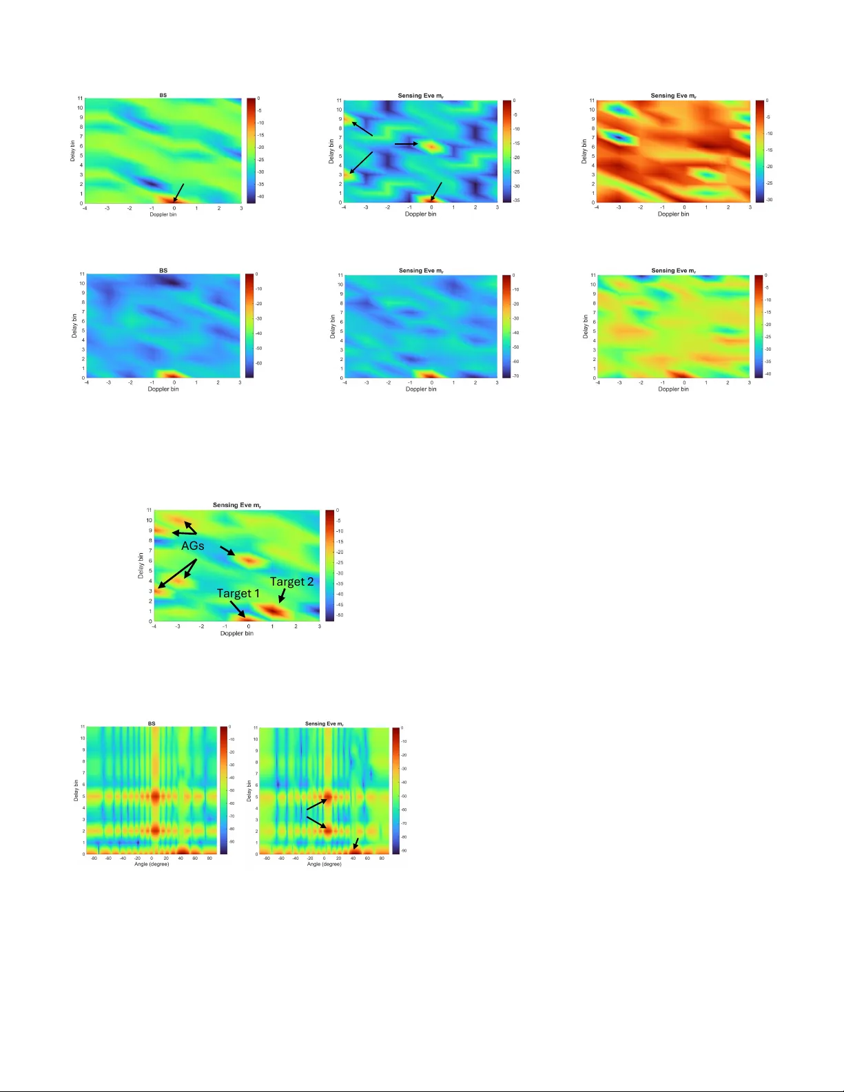
JOURNAL OF L A T E X CLASS FILES, VOL. 18, NO. 9, SEPTEMBER 2020 1 Dual Security for MIMO-OFDM ISA C Systems: Artificial Ghosts or Artificial Noise Y inchao Y ang, Prabhat Raj Gautam, Y athreb Bouazizi, Michael Breza, and Julie McCann Abstract —Integrated sensing and communication (ISA C) en- ables the efficient sharing of wireless resources to support emerging applications, but it also gives rise to new sensing-based security vulnerabilities. Here, potential communication security threats whereby confidential messages intended for legitimate users are intercepted, but also unauthorized receivers (Eves) can passively exploit target echoes to infer sensing parameters with- out users being aware. Despite these risks, the joint protection of sensing and communication security in ISA C systems remains unexplored. T o address this challenge, this paper proposes a two-layer dual-secure ISA C framework that simultaneously protects sensing and communication against passive sensing Eves and communication Eves, without requiring their channel state information (CSI). Specifically , transmit beamformers are jointly designed to inject artificial noise (AN) to introduce interference to communication Eves, while deliberately distorting the reference signal available to sensing Eves to impair their sensing capability . Furthermore, the proposed design generates artificial ghosts (A Gs) with fake angle–range–velocity profiles observable by all receivers. Legitimate receivers can suppress these A Gs, whereas sensing Eves cannot, thereby significantly reducing their probability of correctly detecting the true targets. Numerical results demonstrate that the proposed framework effectively enhances both communication and sensing security , while preserving the performance of communication users and legitimate sensing receivers. Index T erms —ISA C, MIMO, OFDM, and physical layer secu- rity . I . I N T R OD U C T I O N Integrated sensing and communication (ISAC) has been recognized by the International T elecommunication Union (ITU) as one of the key enabling technologies for sixth- generation (6G) wireless systems. By unifying sensing and communication within a common spectrum and hardware, ISA C enables the simultaneous transmission of information and perception of the surrounding en vironment [1]. More importantly , sensing and communication can mutually benefit from each other within the ISA C framework. On one hand, wireless sensing provides real-time environmental awareness, such as object locations and mobility states, which can be exploited by communication systems to perform adapti ve beamforming, handover optimization, and interference man- agement. On the other hand, communication enables sensing systems to exchange information for cooperativ e perception and network-lev el data fusion [2]. Millimeter-wa ve (mmW ave) The authors are with the Department of Computing, Imperial College London, U.K., SW7 2AZ. (e-mail: yinchao.yang@imperial.ac.uk; p.gautam@imperial.ac.uk; y .bouazizi18@imperial.ac.uk; michael.breza04@imperial.ac.uk; j.mccann@imperial.ac.uk). This work was supported by the EPSRC and DSIT through the Communi- cations Hub for Empo wering Distributed Cloud Computing Applications and Research (CHEDDAR) [grant numbers EP/X040518/1 and EP/Y037421/1]. ISA C enables a wide range of emerging applications, such as localization in autonomous vehicular networks [3] and vital- sign detection [4]. Howe ver , since the same signal is reused for both sensing and communication, ISA C systems are inherently exposed to physical-layer security vulnerabilities. The first security concern arises in the communication domain, where a com- munication eavesdropper (Eve) may intercept the transmitted wa veform and attempt to recover confidential information when the encryption ke y is kno wn or compromised. For instance, the target being detected by the transmitter can be the communication Eve who receiv es the joint signal and decodes confidential information, leading to data security concerns. The second and more distinctive threat lies in sensing security . Owing to the broadcast nature of electromagnetic (EM) wav es, a sensing Eve can receiv e the reflected echoes from targets while simultaneously ov erhearing the direct-path signal from the transmitter as a reference wa veform. By jointly processing the two signals, such as using a matched filter (MF), the sensing Eve can infer sensitive tar get information like velocity , geometric features, and e ven physiological information (e.g., respiration and heartbeat), thereby posing sev ere priv acy risks. Communication security in ISAC systems, also referred to as data or information security , has attracted significant research attention in recent years, resulting in a rich body of literature that establishes both solid theoretical founda- tions [5] and practical design methodologies [6]. In partic- ular , a variety of physical-layer keyless security techniques hav e been developed to safeguard confidential information against passive eav esdropping. Representative approaches in- clude information-theoretic secure designs [7], [8], artificial noise (AN) designs [9], [10], secure beamforming optimiza- tions [11], [12], and wav eform design methods [13], [14]. For activ e attacks, such as jamming and spoofing, in which an adversary deliberately injects interfering or deceptiv e signals to disrupt reliable reception or induce false information de- coding, ef fectiv e design methods ha ve also been studied, e.g., [15], [16]. In contrast, sensing security , particularly sensing eavesdrop- ping, is not yet mature in existing ISA C systems [17], [18]. Activ e sensing attacks, such as jamming and spoofing, can often be mitigated using defensiv e mechanisms dev eloped for activ e communication attacks [19], [20]. In contrast, a passiv e sensing Eve does not transmit any signals, yet it can still infer sensitive physical-world information, thereby pos- ing a fundamentally different and more challenging security threat. Existing defensiv e methods designed against passiv e communication Eves cannot be directly applied to sensing Eves. Moreover , unlike sensing-only systems, where secure JOURNAL OF L A T E X CLASS FILES, VOL. 18, NO. 9, SEPTEMBER 2020 2 designs based on radar-centric wav eforms have been exten- siv ely inv estigated [21], [22], many ISA C framew orks employ communication-centric wa veforms to simultaneously support sensing and data transmission. Such communication-centric signaling is inherently more vulnerable to sensing eav esdrop- pers due to the fundamental trade-off between sensing and communication under limited spectral and power resources. In contrast, radar-centric wav eforms, such as FMCW , typically operate over wide bandwidths and exhibit low probability of interception (LPI) characteristics, while often requiring dedicated sensing hardware. Communication wav eforms, how- ev er , are designed for interoperability across standard com- munication devices and are therefore more easily accessible to unauthorized receivers. Consequently , how to ef fectiv ely prev ent sensing eav esdropping in ISAC systems employing communication-centric wav eforms remains largely unexplored [23], [24]. In this context, sev eral recent studies hav e in vestigated sensing security against sensing Eves. In [25], illegal sensing is mitigated by minimizing the signal-to-noise ratio (SNR) at the sensing adversary while simultaneously minimizing the Cram ´ er–Rao bound (CRB) at the legitimate sensing receiv er to preserve sensing accuracy . In [26], a mutual-information (MI) based framew ork is developed, where the MI of the legitimate sensing receiv er is maximized subject to constraints on the maximum allowable MI at the sensing Eves and the minimum signal-to-interference-plus-noise ratio (SINR) requirements of communication users to guarantee commu- nication performance. Similarly , [27] maximizes the SNR of the legitimate sensing recei ver to ensure sensing performance, while imposing SINR constraints for communication users and an upper bound on the sensing Eve’ s SNR to achiev e sensing security . A dual-secure design for cell-free ISA C networks is studied in [28]. Howe ver , the sensing Eve is assumed to hav e no access to the reference signal and can only perform non-coherent energy detection. Consequently , the detection probability of the sensing Eves is optimized, together with minimizing the SNR of the communication Eve to ensure communication security . Nev ertheless, the above-mentioned works commonly rely on the assumption that the channel state information (CSI) of sensing Eves is perfectly known at the transmitter , which may be impractical in realistic deployments. For the case where the CSI of sensing Eves is unknown, i.e., the sensing Eve-agnostic scenario, the authors in [29] enhance sensing security by minimizing the signal-to-artificial- noise ratio while maximizing the SNR of communication users to guarantee communication quality . Howe ver , data security against communication Eves and the sensing performance of the legitimate sensing receiver are not considered. In [30], artificial peaks are created via the ambiguity function (AF) to control the subcarrier power allocation in OFDM systems, resulting in the coexistence of actual and ghost targets in the sensing Eve’ s range profile. Ne vertheless, the ghost targets are confined to the range domain rather than the full an- gle–range–Doppler domain, making it easier for sensing Eves to correctly identify the true tar gets. Similarly , [31] in vestigates both OTFS and OFDM wav eforms for sensing security by op- timizing a Kullback–Leibler di vergence–based detection met- ric, such that strong sidelobes are induced in the sensing Eve’ s range–Doppler profile to obscure the mainlobe. Howe ver , both works assume that the sensing Eve’ s reference signal contains non-line-of-sight (NLoS) components that inherently degrade its quality . In practical scenarios, howe ver , when the sensing Eve is located close to the transmitter , its reference signal may not experience strong NLoS distortion. In [32], sensing security in near-field ISA C systems is achiev ed by exploiting en vironmental scatter to mislead sensing ea vesdroppers. This method relies on prior kno wledge of the scatter information at the transmitter and assumes static scattering environments. Y et, these recent works focus solely on sensing security and do not explicitly consider communication security . An ISAC design considering dual security introduces further challenges and has not been addressed. T o bridge this research gap, where communication and sensing security must be jointly addressed in the absence of CSI of both communication and sensing Eves, we pro- pose a dual-secure design against communication and sensing Eves, without the knowledge of their CSI, while guaranteeing the communication performance and sensing performance for communication users and legitimate sensing receivers, respec- tiv ely . Our main contributions are summarized below: 1) W e propose a secure MIMO-OFDM ISA C design that protects against both sensing and communication Eves without requiring their CSI. By injecting AN, com- munication Eves experience strong interference, thereby effecti vely reducing information leakage. Meanwhile, the injected AN also distorts the reference signal receiv ed by sensing Eves, which limits their estimation capabilities. This mechanism constitutes the first layer of sensing and communication security protection. Howe ver , in the case that if the sensing Eves are located close to the transmitter , their reference signal may remain of high quality . T o address this case, a second layer of sensing se- curity protection is introduced, which deliberately embeds artificial ghosts (AGs) with fake angle–delay–Doppler profiles into sensing Eves’ estimation results. This is achiev ed by designing the AF to generate artificial peaks in the angle–delay–Doppler domain, thereby misleading the sensing Eves toward ghost targets and reducing their probability of correctly detecting the true targets. W ith both defense mechanisms in place, sensing security is ensured regardless of the sensing Eve’ s location or the quality of its recei ved signals. 2) W e establish performance measures for communication performance, communication security , sensing perfor- mance, and sensing security , respectively . W ith all the performance metrics, we formulate a four-way trade- off optimization problem that aims to maximize the sensing performance of the legitimate sensing receiver , subject to constraints on communication performance, communication security , and sensing security under lim- ited resources. T o tackle the resulting non-con vex prob- lem, sev eral con vex surrogate functions are introduced to obtain a tractable formulation. Simulation results verify the effecti veness of the proposed dual-secure design. JOURNAL OF L A T E X CLASS FILES, VOL. 18, NO. 9, SEPTEMBER 2020 3 The remainder of this paper is organized as follows. Sec- tion II introduces the system model, including the underlying assumptions, the signal models of the transmitter and various receiv ers, and the associated signal processing procedures. Section III presents the performance metrics adopted in the design. Section IV formulates the proposed optimization prob- lem and describes the solution. Section V provides numerical results to ev aluate the performance of the proposed design. Finally , Section VI concludes the paper . List of Notations: Capital boldface letters (e.g., A ) denote matrices, while lowercase boldface letters (e.g., a ) denote vectors. Scalars are represented using regular lowercase or uppercase fonts. The sets C , C n × 1 , and C m × n represent a complex number , a complex vector of length n , and a complex m × n matrix, respectiv ely . The identity matrix is denoted by I , and the zero matrix by 0 . The notations [ · ] H , T r( · ) , rank( · ) , and blkdiag( · ) represent the Hermitian transpose, the trace, the rank, and the block diagonal of a matrix, respectiv ely . The l 2 norm is denoted by ||·|| . The symbol ⪰ indicates positiv e semi-definite, while ⊙ and ⊗ denote element-wise and Kronecker product, respectiv ely . Finally , C N (0 , σ 2 ) represents a standard complex Gaussian distribution with zero mean and variance σ 2 . I I . S Y S T E M M O D E L As illustrated in Fig. 1, we consider a monostatic mmW av e ISA C base station (BS) equipped with N t transmit antennas and N r receiv e antennas, serving K communication users (CUs) each equipped with N k antennas. The set of CU indices is denoted by K ≜ { 1 , 2 , . . . , K } . In addition to communication, the BS performs radar sensing to localize L far-field, point-like targets, whose indices form the set L ≜ { 1 , 2 , . . . , L } . In parallel, we consider the presence of sensing Eves equipped with N m r antennas that act as bistatic receiv ers attempting to intercept the target parameters from reflected echoes. The sensing Eve’ s index set is denoted by M r ≜ { 1 , 2 , . . . , M r } . Like wise, a group of communica- tion Eves attempts to overhear the downlink communication signals. Their index set is given by M c ≜ { 1 , 2 , . . . , M c } , and each communication Eve is equipped with N m c antennas. Throughout this paper , we make the following assumptions: Assumption 1. The sensing Eves can perfectly separate the reference signal from the surveillance signal via large antenna arrays (i.e., N m r ≫ N t ), and they know the physical location of the BS. Assumption 2. The BS has no knowledge of sensing or communication Eve’ s position or its existence. Assumption 3. The BS knows the true angle of departure (AoD) of the targets, whereas sensing Eves do not. Assumption 4. The sensing Eves can accurately estimate the angle-of-arriv al (AoA) with respect to the targets. Assumptions 1 and 2 correspond to a worst-case scenario in which sensing Eves remain completely passiv e while the BS B a s e st at i o n , T a r g e t Se ns i ng E v e C ommun i c a t i o n E v e C o m m u ni c a t i o n u s e r Fig. 1. A monostatic ISAC system with a target l ∈ L , a communication user k ∈ K , a bistatic sensing eavesdropper m r ∈ M r , and a communication eav esdropper m c ∈ M c . continuously transmits signals, allowing any recei ver to infer the BS location. Assumption 3 can be realized through an initial beam sweeping or omnidirectional transmission stage, enabling the BS to determine whether targets or objects exist within its cov erage area. Assumption 4 also represents a worst-case scenario in which the sensing Eve can perfectly estimate the AoA, thereby posing a significant threat to the confidentiality of target location information. A. BS T ransmit Signal Model The ISA C BS employs an OFDM wa veform to simultane- ously serve CUs and illuminate the en vironment for sensing. Let N c and N s denote the sets of subcarrier and OFDM time slot indices, respectiv ely . For each subcarrier-time slot pair ( n c , n s ) , the modulated symbol vector is s n c ,n s = [ s n c ,n s , 1 , . . . , s n c ,n s ,K ] T ∈ C K × 1 , where s n c ,n s ,k denotes the modulated symbol of user k , drawn from a constellation set S . The symbols are precoded and embedded with AN, resulting in the transmit signal: x n c ,n s = W n c ,n s s n c ,n s + q n c ,n s , (1) where W n c ,n s ∈ C N t × K is the beamforming matrix with each column w n c ,n s ,k ∈ C N t × 1 being the beamforming vector of each user k , and q n c ,n s ∈ C N t × 1 is the AN vector . Follo wing from [33], [34], we assume E s n c ,n s s H n c ,n s = I and E s n c ,n s q H n c ,n s = 0 , which indicates that the symbols are uncorrelated across users and are independent of the AN, respectiv ely . The corresponding baseband OFDM signal is given by [35] x ( t ) = X n c ∈N c X n s ∈N s x n c ,n s e j 2 πn c ∆ f t n s rect t n s T tot , (2) where t n s = t − n s T tot , ∆ f = 1 /T is the subcarrier spacing, T tot = T + T cp denotes the total symbol duration, with T and T cp being the symbol duration and the cyclic prefix (CP) duration, respectively . Finally , the baseband signal in (2) is up-con verted to the carrier frequency f c , resulting in the radio frequency (RF) domain transmit wav eform x RF ( t ) = x ( t ) e j 2 πf c t . JOURNAL OF L A T E X CLASS FILES, VOL. 18, NO. 9, SEPTEMBER 2020 4 B. BS Receive Signal Model The BS observes echoes reflected by all targets in the set L . The receiv ed RF domain signal can be expressed as y RF ,B ( t ) = X l ∈L H l,B x RF ( t − τ l,B ) e j 2 πµ l,B t + n ( t ) = X l ∈L β l,B a r ( θ l,B ) a H t ( θ l,t ) x RF ( t − τ l,B ) e j 2 πµ l,B t + n ( t ) , (3) where β l,B denotes the complex path loss that incorporates propagation loss and the radar cross section (RCS) of the l -th target. The vectors a t ( θ l,t ) ∈ C N t × 1 and a r ( θ l,B ) ∈ C N r × 1 are the transmit and receiv e steering vectors ev aluated at the angles from the BS to target l (i.e., AoD) and from target l to BS (i.e., AoA), respectiv ely . The two-way trip delay is giv en by τ l,B = d t,l + d l,B c , where d t,l and d l,B denote the propagation distances from the BS to the target and from the target to BS, respectively , and c is the speed of light. The Doppler shift associated with tar get l is µ l,B = ( v t,l + v l,B ) f c c , with v t,l and v l,B representing the radial velocities along the BS–target and target–recei ver directions, respectively . Finally , n ( t ) ∼ C N ( 0 , σ 2 r I N r ) denotes the additiv e white Gaussian noise (A WGN). After RF down-con version, (3) becomes y B ( t ) = X l ∈L ˜ β l,B a r ( θ l,B ) a H t ( θ l,t ) X n c ∈N c X n s ∈N s x n c ,n s · e j 2 πn c ∆ f ( t n s − τ l,B ) e j 2 πµ l,B t rect t n s − τ l,B T tot + ˜ n ( t ) , (4) where ˜ β l,B = β l,B e − j 2 πf c τ l,B and ˜ n ( t ) = n ( t ) e − j 2 πf c τ l,B . W e partition the recei ved signal with respect to each symbol slot [36]: y n s ,B ( t ) ≜ y B ( t + n s T tot ) , ∀ n s ∈ N s . (5) T o obtain the discrete-time signal, we sample (5) with a sampling rate of f s = N c ∆ f . Accordingly , the p -th sample is giv en by y n s ,B [ p ] = y n s ,B ( p/f s ) = X l ∈L ˜ β l,B a r ( θ l,B ) a H t ( θ l,t ) X n c ∈N c x n c ,n s e j 2 πn c p N c · e − j 2 πn c ∆ f τ l,B e j 2 πµ l,B p N c ∆ f e j 2 πµ l,B n s T tot + ˜ n [ p ] , (6) with ˜ n [ p ] = ˜ n ( p N c ∆ f + n s T tot ) . T o av oid inter-carrier inter- ference (ICI), the OFDM spacing must satisfy µ l,B / ∆ f ≪ 1 , as discussed in [37]. Thus, (6) can be approximated as y n s ,B [ p ] ≈ X l ∈L ˜ β l,B a r ( θ l,B ) a H t ( θ l,t ) X n c ∈N c x n c ,n s · e j 2 πn c p N c e − j 2 πn c ∆ f τ l,B e j 2 πµ l,B n s T tot + ˜ n [ p ] . (7) Then, by applying an N c -point discrete Fourier transform (DFT) on (7), the received frequency-domain sample at sub- carrier n c can be obtained as y n c ,n s ,B = 1 N c N c − 1 X p =0 y n s ,B [ p ] e − j 2 πn c p/ N c = X l ∈L ˜ β l,B a r ( θ l,B ) a H t ( θ l,t ) x n c ,n s e − j 2 πn c ∆ f τ l,B e j 2 πµ l,B n s T tot + ¯ n , (8) where ¯ n is the frequency-domain A WGN. W ith (8), BS first estimates the AoA using high-resolution algorithms such as MUSIC [38]. Then, BS applies the spatial filtering applied to (8) yields the following result: y n c ,n s ,B = X l ∈L ˜ β l,B a H t ( θ l,t ) x n c ,n s · e − j 2 πn c ∆ f τ l,B e j 2 πµ l,B n s T tot + ¯ n = X l ∈L X n t ∈N t ˜ β l,B √ N t e − j 2 π d t λ sin θ l,t n t x n c ,n s [ n t ] · e − j 2 πn c ∆ f τ l,B e j 2 πµ l,B n s T tot + ¯ n, (9) where x n c ,n s [ n t ] is the n t -th element of the vector x n c ,n s , and the antenna index is collected by the set N t . Remark 1. In practical systems, all tar get parameters can be jointly estimated using multi-dimensional spectral estima- tion techniques, such as multi-dimensional periodograms or subspace-based methods. However , since the AoA is deter- mined by the r eceiver side and is independent of transmitter side designs, we assume that the AoA has been accurately estimated beforehand. This allows the r emaining parameter estimations to focus e xclusively on delay , AoD, and Doppler , which ar e directly influenced by the transmit signal design. C. Sensing Eve Signal Model The sensing Eve receiv es echo signals reflected from the targets through a bistatic propagation path. The received RF- domain signal is modeled as y RF ,m r ( t ) = X l ∈L H l,m r x RF ( t − τ l,m r ) e j 2 πµ l,m r t + n ( t ) = X l ∈L β l,m r a r ( θ l,m r ) a H t ( θ l,t ) x RF ( t − τ l,m r ) e j 2 πµ l,m r t + n ( t ) , (10) where β l,m r denotes the bistatic path loss, θ l,m r represents the AoA from the l -th target to the m r -th sensing Eve and a r ( θ l,m r ) ∈ C N m r × 1 is the receiv e steering vector , τ l,m r and µ l,m r denote the corresponding time delay and Doppler shift, respectiv ely , and n ( t ) is A WGN. 1) Reference Signal Reception: Following Assumption 1 , the sensing Eve is able to observe a reference signal directly from the BS. This observed signal is denoted by y r,m r ( t ) = H r,m r x RF ( t ) + n m r ( t ) , (11) where H r,m r ∈ C N m r × N t denotes the LoS channel between BS and the sensing Eve. Since the sensing Eve is aw are of the transmitter’ s physical location, the reference signal can be obtained via the minimum variance unbiased (MVU) estimator [39], i.e., ˆ x n c ,n s = H H r,m r H r,m r − 1 H H r,m r y r,m r ( t ) . 2) Spatially F ilter ed Echo Signal: By applying the same down-con version, sampling, DFT , and spatial filtering steps as in BS’ s signal processing procedure, the sensing Eve obtains the following frequency-domain echo: y n c ,n s ,m r = X l ∈L X n t ∈N t ˜ β l,m r √ N t e − j 2 π d t λ sin θ l,t n t x n c ,n s [ n t ] · e − j 2 πn c ∆ f τ l,m r e j 2 πµ l,m r n s T tot + ¯ n m r , (12) JOURNAL OF L A T E X CLASS FILES, VOL. 18, NO. 9, SEPTEMBER 2020 5 B a s e st at i o n T a r g e t , Se ns i ng E v e , Fig. 2. Illustration of the sensing security vulnerability in an ISAC system. When only the distance d and the AoA angle θ l,m r are e xposed, the sensing Eve can infer that the target lies some where along the dotted locus but cannot determine its exact position. If the AoD θ l,t is also re vealed, the target’ s location becomes fully identifiable. where ˜ β l,m r = β l,m r e − j 2 πf c τ l,m r and ¯ n m r denotes A WGN in the frequency domain. Remark 2. Under the worst-case assumption where the trans- mitter’ s location is known to the sensing Eves ( Assumption 1 ) and the adversary can accurately estimate the AoA ( Assump- tion 4 ), the tar get must lie on a deterministic line (dotted line) as illustrated in F ig. 2. Consequently , it is essential to pre vent the adversary fr om r ecovering θ l,t , τ l,m r , and µ l,m r , since these parameters pr ovide additional geometric information that enables localization of the tar get. F or e xample, knowing two angles and one side of a triangle allows the tar get position to be uniquely determined. D. Echo Signal Pr ocessing For the BS and the sensing Eves, the objectiv e is to detect the presence of targets and, upon detection, to estimate their physical parameters. The parameters of interest are defined as Ψ B = θ l,t , τ l,B , µ l,B and Ψ m r = θ l,t , τ l,m r , µ l,m r , ∀ l ∈ L , respectively . For design traceability , we assume that the delay and Doppler shifts lie on the discrete resolution grid [40]. That is, τ l = ℓ l N c ∆ f , µ l = ν l N s T tot , where ℓ l and ν l denote the delay and Doppler bins, respectively . Therefore, the signals in (9) and (12) can be written in matrix form as Y i = X l ∈L ˜ β l,i D ℓ l,i ˜ X l D ν l,i + N , i ∈ [ B , m r ] , (13) where Y i [ n c , n s ] = y n c ,n s ,i , ˜ X l = I N c ⊗ a H t ( θ l,t ) X , X ∈ C N c N t × N s , D ℓ l,i = diag 1 , e − j 2 πℓ l,i 1 N c , . . . , e − j 2 πℓ l,i N c − 1 N c , D ν l,i = diag 1 , e j 2 πν l,i 1 N s , . . . , e j 2 πν l,i N s − 1 N s . T o estimate Ψ i , we employ a three-dimensional MF across angle, delay , and Doppler domains. The MF output is given by [41] ˆ Ψ i = F H N c Y i ⊙ ( F θ X ∗ i ) F N s , i ∈ [ B , m r ] , (14) where F N c and F N s denote the DFT matrices for delay and Doppler processing, F θ is the steering matrix, and ˆ Ψ i = [ ˆ θ l,t , ˆ τ l,i , ˆ µ l,i ] contains the estimated parameters. E. Communication Models For a communication user k ∈ K , the receiv ed time-domain signal is giv en by y k ( t ) = H k x ( t ) + n k ( t ) , (15) where H k ∈ C N k × N t is the channel between transmitter and user k , and n k ∼ C N (0 , σ 2 c I ) is A WGN. Follo wing the similar OFDM signal processing procedure as shown in (4)-(8), the receiv ed frequency domain signal is given by y n c ,n s ,k = H n c ,n s ,k x n c ,n s + ¯ n k , (16) where H n c ,n s ,k ∈ C N k × N t denotes the downlink channel vector on subcarrier n c and symbol n s , and ¯ n k is A WGN. Perfect CSI is assumed at the BS, obtainable through standard uplink–downlink pilot estimation prior to the beamforming design. Substituting (1) into (16), we can decompose the receiv ed signal as y n c ,n s ,k = H n c ,n s ,k w n c ,n s ,k s n c ,n s ,k | {z } Desired signal + X k ′ ∈K ,k ′ = k H n c ,n s ,k w n c ,n s ,k ′ s n c ,n s ,k ′ | {z } Multi-user interference + H n c ,n s ,k q n c ,n s | {z } Artificial noise + ¯ n k , (17) where w n c ,n s ,k ∈ C N t × 1 is the k -th column of W n c ,n s . For the communication Eve m c ∈ M c , its intercepted signal in the time-domain is given by y m c ( t ) = H m c x ( t ) + n m c ( t ) , (18) where H m c ∈ C N m c × N t is the channel between transmitter and communication Eve m c , and n m c ∼ C N (0 , σ 2 c I ) is A WGN. After standard OFDM procedures, the intercepted signal in relation to the k -th CU is giv en by y n c ,n s ,k,m c = H n c ,n s ,m c w n c ,n s ,k s n c ,n s ,k | {z } Intercepted signal + X k ′ ∈K ,k ′ = k H n c ,n s ,m c w n c ,n s ,k ′ s n c ,n s ,k ′ | {z } Multi-user interference + H n c ,n s ,m c q n c ,n s | {z } Artificial noise + ¯ n m c , (19) where H n c ,n s ,m c ∈ C N m c × N t denotes the downlink channel vector on subcarrier n c and symbol n s for the communication Eve m c ∈ M c . I I I . P E R F O R M A N C E M E T R I C S In this section, we present the performance metrics for sensing, communication, and security , respectively . JOURNAL OF L A T E X CLASS FILES, VOL. 18, NO. 9, SEPTEMBER 2020 6 T ABLE I D E SI R E D A M B IG U I TY F UN C T I ON B EH A V I OR F OR BS A ND T HE S EN S I N G E V E Mainlobe(s) Sidelobe(s) BS χ (0 , 0 , θ l,t , θ l,t ) 2 = 1 χ (∆ ℓ = 0 , ∆ ν = 0 , θ l,t , ˆ θ l,t = θ l,t ) 2 = 0 The sensing Eve χ (∆ ℓ = 0 , ∆ ν = 0 , θ l,t , ˆ θ l,t = θ l,t ) 2 = 1 χ (0 , 0 , θ l,t , θ l,t ) 2 = 0 A. Sensing Accuracy for BS T o characterize the sensing capability of the BS, we consider the post–MF SNR ev aluated at the correct delay , Doppler , and angle, i.e., ˆ τ l,B = τ l,B , ˆ ν l,B = ν l,B and ˆ θ l,t = θ l,t . Since BS possesses perfect knowledge of the reference signal without AN, the resulting post-MF SNR at each ( n c , n s ) resource block of target l can be expressed as γ n c ,n s ,l,B = ˜ β 2 l,B a H r ( θ l,B ) 2 a H t ( θ l,t ) W n c ,n s 2 σ 2 r . (20) B. Sensing Security using Artificial Ghosts The MF operation expressed in (14) is employed to effi- ciently estimate the target parameters. For analytical purposes and assuming the worst-case where sensing Eve’ s estimated reference signal is error-free, i.e., ˆ x n c ,n s = x n c ,n s , we rewrite the MF output explicitly as χ ˆ ℓ l , ˆ ν l , θ l,t , ˆ θ l,t = X n ′ t ∈N t X n c ∈N c X n s ∈N s y n c ,n s x ∗ n c ,n s [ n ′ t ] · 1 √ N t e j 2 π d t λ sin ˆ θ l,t n ′ t e j 2 π ˆ ℓ l n c N c e − j 2 π ˆ ν l n s N s . (21) By substituting (12) into (21), it can be observed that the MF output depends explicitly on W n c ,n s and q n c ,n s . This naturally leads to the characterization of the ambiguity function (AF), which describes the autocorrelation of the transmitted and received ISA C signal across angle, delay , and Doppler [30], [42]. By neglecting the path loss coef ficients and noise terms, and substituting into (21), we obtain the expected AF expression shown in (22). The notations used in (22) are giv en below: A ∆ ℓ, ∆ ν, θ l,t , ˆ θ l,t = 1 N t a t ( θ l,t ) a H t ( ˆ θ l,t ) e − j 2 π n c N c (∆ ℓ ) e j 2 π n s N s (∆ ν ) , ¯ A ( θ l,t ) = 1 √ N t a t ( θ l,t ) ⊗ I N c N s , ¯ W n c ,n s ∈ C N t × N t = W n c ,n s W H n c ,n s , W = blkdiag ¯ W 1 , 1 , . . . , ¯ W N c ,N s , Q n c ,n s ∈ C N t × N t = q n c ,n s q H n c ,n s , ¯ Q = blkdiag ( Q 1 , 1 , . . . , Q N c ,N s ) , and D ∆ ℓ , D ∆ ν has been defined in (13). As summarized in T able I, and assuming that (22) is normalized to lie within [0 , 1] after squaring, achie ving high sensing accuracy for BS and ensuring sensing security against Eve constitute two inherently contrasting design objectiv es. Since (22) is determined by W and ¯ Q that are observed by all receiv ers, these objectiv es are fundamentally conflicting. T o navigate this tradeoff, we aim to design the beamformers such that BS retains a dominant and unambiguous mainlobe at the true target location, while the sensing Eves are div erted tow ard AGs, thereby reducing their probability of correctly detecting the actual target. As such, we consider the PSL [43] and the ISL [37] that quantify the highest sidelobe peak and the total sidelobe energy relativ e to the mainlobe, respectiv ely . The PSL for- mulation is giv en by PSL l = | χ (∆ ℓ g , ∆ ν g , θ l,t , θ g ,t ) | 2 | χ (0 , 0 , θ l,t , θ l,t ) | 2 ≥ η PSL , ∀ g ∈ G , g / ∈ L ∪ K , (23) where G denotes the set of A G indices, and each ghost has the delay–Doppler-angle coordinates of (∆ ℓ g , ∆ ν g , θ g ,t ) . And the ISL formulation is given by: ISL l = P ˆ θ l,t P N c − 1 , N s − 1 ∆ ℓ =0 , ∆ ν =0 (∆ ℓ, ∆ ν ) =(0 , 0) χ (∆ ℓ, ∆ ν, θ l,t , ˆ θ l,t ) 2 | χ (0 , 0 , θ l,t , θ l,t ) | 2 ≥ η ISL , (24) where ˆ θ l,t ∈ − π 2 , π 2 , ˆ θ l,t = θ l,t . C. Sensing Security Using Artificial Noise AN is used to deliberately distort the reference signal observed by a potential sensing Eve, as shown in (11). T o quantify the resulting degradation in Eve’ s sensing capability under the MIMO setting ( Assumption 1 ), we consider the av erage data rate at a hypothetical Eve located at angle θ m r : C m r = 1 N c N s X n c ∈N c , n s ∈N s log det I + H r,m r ¯ W n c ,n s H H r,m r H r,m r Q n c ,n s H H r,m r + σ 2 c I ! , (25) where H r,m r = a r ( θ m r ) a H t ( θ m r ) , with θ m r ∈ − π 2 , π 2 , θ m r / ∈ K denoting the angular location of a potential sensing Eve. W e note that the path loss effect is omitted in (25) due to the lack of knowledge about Eve’ s distance (i.e., Assumption 2 ). As a result, (25) characterizes the best-case sensing capability of Eve. In practice, propagation loss would further attenuate the recei ved signal and hence reduce the performance for sensing Eves [29], [44]. D. Communication P erformance and Security Based on the signal model in (17), the average data rate of the k -th CU is expressed in (26), where W n c ,n s ,k = w n c ,n s ,k w H n c ,n s ,k and Q n c ,n s = q n c ,n s q H n c ,n s . JOURNAL OF L A T E X CLASS FILES, VOL. 18, NO. 9, SEPTEMBER 2020 7 χ ˆ ℓ l , ˆ ν l , θ l,t , ˆ θ l,t = 1 N t E ( X n t ,n ′ t ∈N t X n c ∈N c X n s ∈N s e − j 2 π d t λ sin θ l,t n t x n c ,n s [ n t ] e − j 2 πℓ l n c N c e j 2 πν l n s N s · x ∗ n c ,n s [ n ′ t ] e j 2 π d t λ sin ˆ θ l,t n ′ t e j 2 π ˆ ℓ l n c N c e − j 2 π ˆ ν l n s N s ) = 1 N t E ( X n c ∈N c X n s ∈N s x H n c ,n s a t ( θ l,t ) a H t ( ˆ θ l,t ) x n c ,n s e − j 2 π n c N c (∆ ℓ ) e j 2 π n s N s (∆ ν ) ) = X n c ∈N c X n s ∈N s T r A ∆ ℓ, ∆ ν, θ l,t , ˆ θ l,t ¯ W n c ,n s + T r A ∆ ℓ, ∆ ν, θ l,t , ˆ θ l,t Q n c ,n s = T r ¯ A ( θ l,t )( D ∆ ℓ ⊗ D ∆ ν ) ¯ A H ( ˆ θ l,t ) W + T r ¯ A ( θ l,t )( D ∆ ℓ ⊗ D ∆ ν ) ¯ A H ( ˆ θ l,t ) ¯ Q ≜ χ ∆ ℓ, ∆ ν, θ l,t , ˆ θ l,t . (22) C k = 1 N c N s X n c ∈N c , n s ∈N s log det I + H n c ,n s ,k W n c ,n s ,k H H n c ,n s ,k H n c ,n s ,k X k ′ ∈K , k ′ = k W n c ,n s ,k ′ + Q n c ,n s H H n c ,n s ,k + σ 2 c I − 1 , (26) C k,m c = 1 N c N s X n c ∈N c , n s ∈N s log det I + H n c ,n s ,m c W n c ,n s ,k H H n c ,n s ,m c H n c ,n s ,m c X k ′ ∈K , k ′ = k W n c ,n s ,k ′ + Q n c ,n s H H n c ,n s ,m c + σ 2 c I − 1 , (27) For a communication Eve index ed by m c ∈ M c , its data rate is shown in (27), where H n c ,n s ,m c = a H r ( θ m c ) a t ( θ m c ) , with θ m c ∈ − π 2 , π 2 , θ m c / ∈ K denoting the angular location of a potential communication Eve. Finally , the worst-case secrecy rate of the k -th CU, which quantifies the communication security , is giv en by S k = min m c ∈M c [ C k − C k,m c ] + , (28) where [ A ] + means max( A, 0) . I V . D UA L S E C U R E D E S I G N F O R M I M O - O F D M I S A C S Y S T E M S This section formulates the dual-secure ISAC design prob- lem and proposes an algorithm for solving the resulting noncon ve x problem. A. Problem F ormulation The design objecti ve is to ensure reliable sensing per- formance while simultaneously guaranteeing communication performance, sensing security , and communication security . Accordingly , the optimization problem is formulated based on the aforementioned performance metrics and is presented as follows: max W n c ,n s ,k , Q n c ,n s ,η B η B (29a) s.t. γ n c ,n s ,l,B ≥ η B , ∀ n c ∈ N c , ∀ n s ∈ N s , ∀ l ∈ L , (29b) C m r ≤ η E , ∀ m r ∈ M r , (29c) PSL l ≥ η PSL , ∀ l ∈ L , (29d) ISL l ≥ η ISL , ∀ l ∈ L , (29e) S k ≥ η s , ∀ k ∈ K , (29f) X n c ∈N c X n s ∈N s T r X k ∈K W n c ,n s ,k + Q n c ,n s ! ≤ P t , (29g) W n c ,n s ,k ⪰ 0 , Q n c ,n s ⪰ 0 , (29h) rank ( W n c ,n s ,k ) = 1 . (29i) The objecti ve function in (29a), together with constraint (29b), is designed to maximize the BS’ s sensing performance as quantified in (20). Constraint (29c) limits the quality of the sensing Eve’ s reference signal, thereby deliberately impairing its sensing capability . Constraint (29d) facilitates the generation of A Gs, whereas constraint (29e) controls sidelobe levels to promote energy focusing on the true targets and AGs. Constraint (29f) ensures secure communication, and constraint (29g) enforces the transmit power budget P t . Lastly , constraints (29h) and (29i) guarantee that the resulting matrices are decomposable into feasible per-user beamforming structures. Follo wing from [45], [46], we drop the rank-one constraint due to its non-con ve x behavior . A rank-one solution JOURNAL OF L A T E X CLASS FILES, VOL. 18, NO. 9, SEPTEMBER 2020 8 1 N c N s X n c ∈N c ,n s ∈N s log det H r,m r ¯ W ( e ) n c ,n s + Q ( e ) n c ,n s H H r,m r + σ 2 c I + T r H r,m r ¯ W ( e ) n c ,n s + Q ( e ) n c ,n s H H r,m r + σ 2 c I − 1 H r,m r ¯ W n c ,n s − ¯ W ( e ) n c ,n s + Q n c ,n s − Q ( e ) n c ,n s H H r,m r − log det H r,m r Q n c ,n s H H r,m r + σ 2 c I ≤ η E , (30) η PSL T r ¯ A ( θ l,t ) ¯ A H ( θ l,t ) W + T r ¯ A ( θ l,t ) ¯ A H ( θ l,t ) ¯ Q 2 − f PSL ( W ( e ) , ¯ Q ( e ) ) 2 + 2 ℜ f ∗ PSL ( W ( e ) , ¯ Q ( e ) ) · h T r ¯ A ( θ l,t )( D ℓ g ⊗ D ν g ) ¯ A H ( θ g,t ) W − W ( e ) + T r ¯ A ( θ l,t )( D ℓ g ⊗ D ν g ) ¯ A H ( θ g,t ) ¯ Q − ¯ Q ( e ) i ! ≤ 0 , (31) where f PSL ( W ( e ) , ¯ Q ( e ) ) ≜ T r ¯ A ( θ l,t )( D ℓ g ⊗ D ν g ) ¯ A H ( θ g,t ) W ( e ) + T r ¯ A ( θ l,t )( D ℓ g ⊗ D ν g ) ¯ A H ( θ g,t ) ¯ Q ( e ) . η ISL T r ¯ A ( θ l,t ) ¯ A H ( θ l,t ) W + T r ¯ A ( θ l,t ) ¯ A H ( θ l,t ) ¯ Q 2 − X ˆ θ l,t N c − 1 X ∆ ℓ =1 N s − 1 X ∆ ν =1 f ISL ( W ( e ) , ¯ Q ( e ) ) 2 + 2 ℜ f ∗ ISL ( W ( e ) , ¯ Q ( e ) ) · h T r ¯ A ( θ l,t )( D ∆ ℓ ⊗ D ∆ ν ) ¯ A H ( ˆ θ l,t ) W − W ( e ) + T r ¯ A ( θ l,t )( D ∆ ℓ ⊗ D ∆ ν ) ¯ A H ( ˆ θ l,t ) ¯ Q − ¯ Q ( e ) i ! ≤ 0 , (32) where f ISL ( W ( e ) , ¯ Q ( e ) ) ≜ T r ¯ A ( θ l,t )( D ∆ ℓ ⊗ D ∆ ν ) ¯ A H ( ˆ θ l,t ) W ( e ) + T r ¯ A ( θ l,t )( D ∆ ℓ ⊗ D ∆ ν ) ¯ A H ( ˆ θ l,t ) ¯ Q ( e ) . can be recovered from the optimal solutions via Gaussian randomization. B. Problem T ransformation The optimization problem is non-con ve x due to the con- straints in (29c)–(29f). W e first consider constraint (29c). By rewriting (29c) in a difference-of-con vex (DC) form [47] and applying a first-order T aylor approximation to its concav e component, a con ve x surrogate constraint is obtained, as shown in (30). The matrices ¯ W ( e ) n c ,n s and Q ( e ) n c ,n s are updated iterativ ely . Using the same approach, constraint (29d) is reformulated into a DC representation and subsequently approximated via a first-order T aylor expansion, leading to the con ve x surrogate in (31). In this step, the auxiliary matrices W ( e ) and ¯ Q ( e ) are constructed from ¯ W ( e ) n c ,n s and Q ( e ) n c ,n s . Constraint (29e) already admits a DC structure and can therefore be directly approximated by a con ve x surrogate, as giv en in (32). Finally , following the same procedure as for (29c), con- straint (29f) is approximated by the conv ex surrogate shown in (33). Therefore, problem (29) has been equiv alently reformulated as the following con ve x optimization problem: max W n c ,n s ,k , Q n c ,n s ,η B η B (34a) s.t. γ n c ,n s ,l,B ≥ η B , ∀ n c ∈ N c , ∀ n s ∈ N s , ∀ l ∈ L , (34b) (30) , (31) , (32) , (33) , (29g) . (34c) Since all constraints and the objectiv e function are con- ve x with respect to the variables, problem (34) constitutes a standard con ve x program and can be efficiently solved using off-the-shelf solvers. The iterativ e procedure for solving problem (34) is sho wn in Algorithm 1. Algorithm 1 Iterati ve Optimization for Solving Problem (34) 1: Set the iteration number e = 1 , and randomly initialize W (0) n c ,n s and Q (0) n c ,n s . 2: repeat 3: Solve (34) to obtain W n c ,n s ,k and Q n c ,n s . 4: Update W ( e ) n c ,n s ,k = W n c ,n s ,k and Q ( e ) n c ,n s = Q n c ,n s . 5: Calculate ¯ W ( e ) n c ,n s , W ( e ) , and ¯ Q ( e ) using W ( e ) n c ,n s ,k and Q ( e ) n c ,n s . 6: e = e + 1 . 7: until ¯ W ( e ) n c ,n s − ¯ W ( e − 1) n c ,n s ≤ ϵ and Q ( e ) n c ,n s − Q ( e − 1) n c ,n s ≤ ϵ . 8: Apply Gaussian randomization to find rank-one solutions w n c ,n s ,k based on W n c ,n s ,k , and q n c ,n s based on Q n c ,n s . V . S I M U L A T I O N R E S U L T S This section presents numerical results that ev aluate the performance of the proposed dual-secure ISA C framework. Unless otherwise specified, all simulation parameters follow the default values listed in T able II. A uniform linear array (ULA) with half-wa velength antenna spacing is employed at the BS, and quadrature phase-shift keying (QPSK) modulation is adopted, i.e., the constellation set S corresponds to QPSK. The A G profiles in (22) and (23) are configured at (0 , 5 , 62 ◦ ) , (0 , 2 , 35 ◦ ) , and (3 , 4 , 40 ◦ ) . The BS is located at (0 , 0) , the sensing Eve at (3 , 1) , and the sensing target at (12 , 11) with a velocity of 46 m / s . T wo CUs are located at (15 , − 1) JOURNAL OF L A T E X CLASS FILES, VOL. 18, NO. 9, SEPTEMBER 2020 9 1 N c N s X n c ∈N c ,n s ∈N s log det H n c ,n s ,k X k ∈K W n c ,n s ,k + Q n c ,n s H H n c ,n s ,k + σ 2 c I + log det H n c ,n s ,m c X k ′ ∈K , k ′ = k W n c ,n s ,k ′ + Q n c ,n s H H n c ,n s ,m c + σ 2 c I − log det ( Ξ n c ,n s ,k ) − T r Ξ − 1 n c ,n s ,k Ξ n c ,n s ,k − H n c ,n s ,k X k ′ ∈K , k ′ = k W n c ,n s ,k ′ + Q n c ,n s H H n c ,n s ,k − σ 2 c I − log det ( Ξ n c ,n s ,m c ) − T r Ξ − 1 n c ,n s ,m c Ξ n c ,n s ,m c − H n c ,n s ,m c X k ∈K W n c ,n s ,k + Q n c ,n s H H n c ,n s ,m c − σ 2 c I ≥ η s , (33) where Ξ n c ,n s ,k = H n c ,n s ,k X k ′ ∈K , k ′ = k W ( e ) n c ,n s ,k ′ + Q ( e ) n c ,n s H H n c ,n s ,k + σ 2 c I , Ξ n c ,n s ,m c = H n c ,n s ,m c X k ∈K W ( e ) n c ,n s ,k + Q ( e ) n c ,n s H H n c ,n s ,m c + σ 2 c I . T ABLE II S I MU L A T I ON S ET T I N GS Parameter Symbol V alue Carrier frequency f c 24 GHz OFDM symbol duration T 8 . 33 × 10 − 6 Cyclic prefix duration T cp 0 . 59 × 10 − 6 Number of subcarriers N c 12 Number of symbols N s 8 Number of transmit/receive antennas N t , N r 16 Sensing Eve’ s receiv e antennas N m r 24 Communication noise power σ 2 c -70 dBm Sensing noise power σ 2 r -70 dBm Power b udget P t 50 dBm and (9 , − 4) , respecti vely , while the communication Eve is located at (2 , − 8) . Unless otherwise stated, the sensing Eve is assumed to have perfectly recovered the reference signal, i.e., ˆ x n c ,n s = x n c ,n s . Each communication Eve and each CU is equipped with tw o antenna elements. All channels are modeled using geometry-based channel models with free-space path loss. A. F our -W ay T rade-Of fs Enabled by Artificial Ghosts In this subsection, we in vestigate how the design of A Gs affects the sensing performance, sensing security , commu- nication performance, and communication security . W e first examine the impact of the ISL. As shown in Fig. 3, for a fixed value of η PSL and η ISL , increasing the secrecy rate requirement Fig. 3. The sensing SNR for BS ( γ n c ,n s ,l,B ) versus the secrecy rate for users ( η S ). The values of η PSL is set to -25 dB and η E = 3 bps/Hz. Sensing secure Fig. 4. The sensing SNR for BS ( γ n c ,n s ,l,B ) versus the secrecy rate for users ( η S ). The values of η ISL is set to -4 dB and η E = 5 bps/Hz. η S leads to a reduction in the sensing SNR at the BS. This indicates that achieving higher communication security comes at the cost of degraded sensing performance. The underlying reason is that stricter communication secrecy requirements demand more transmit power to be allocated toward the CUs, thereby reducing the resources av ailable for coherent sensing. From the communication perspective, communication per- formance improv es with increasing communication security , since both metrics benefit from higher signal power directed tow ard the legitimate users. This rev eals an inherent trade-off among sensing performance, communication performance, and JOURNAL OF L A T E X CLASS FILES, VOL. 18, NO. 9, SEPTEMBER 2020 10 Sensing secure with AG Fig. 5. The sensing Eve reference signal transmission rate ( η E ) versus user secrecy rate ( η S ). communication security , where enhanced communication per- formance and security inevitably degrade sensing performance. Notably , increasing the ISL, e.g., from − 4 dB to 2 dB , further reduces the sensing SNR when the communication security lev el is fixed. A larger ISL allows more energy to be distributed ov er sidelobes, which enhances sensing security . Howe ver , this sidelobe energy leakage reduces the po wer av ailable for both coherent sensing at the BS and transmission toward the CUs, thereby degrading communication performance and com- munication security . Consequently , increasing the ISL simul- taneously deteriorates sensing performance, communication performance, and communication security , while improving sensing security . In Fig. 4, we in vestigate the impact of the PSL. Similar to the observations in Fig. 3, for fixed v alues of η PSL and η ISL , increasing the secrecy rate requirement η S leads to a reduction in the sensing SNR at the BS, indicating that enhanced communication performance and security is achiev ed at the expense of sensing performance. Moreover , increasing the PSL threshold, e.g., from − 25 dB to − 10 dB , improves sensing security by strengthening the sidelobes that represent the A Gs. Howe ver , when the communication secrecy rate is fixed, a larger PSL results in a noticeable degradation of the sensing SNR. This is because a higher PSL permits stronger sidelobe lev els to realize more prominent AGs, which consumes additional transmit power and reduces the energy that can be coherently focused on sensing. As a result, less power is available to ensure high sensing performance at the BS. B. F our -W ay T rade-Of fs Enabled by Artificial Noise In this subsection, we focus on the impact of AN. As shown in Fig. 5, for fixed values of η PSL and η ISL , increasing the secrecy rate requirement η S leads to a reduction in the sensing Eve’ s reference signal transmission rate η E . This indicates that enhancing communication security simultaneously improves sensing security under the AN-assisted design. The reason is that stricter secrecy requirements necessitate injecting more AN to suppress potential communication eav esdroppers, which also degrades the reference signal quality receiv ed at the sensing Eve. For fixed v alues of η ISL and η S , increasing the PSL threshold results in a further reduction of η E . This is because allocating more transmit power to sidelobe shaping for A Gs generation reduces the effecti ve beamforming gain tow ard the sensing Eve, thereby lowering the achie vable reference signal rate. By contrast, when η PSL and η S are fixed, increasing η ISL leads to a slight increase in η E . This occurs since higher ISL permits additional sidelobe energy that is not exclusi vely associated with the AGs, allowing the sensing Eve to opportunistically collect part of this leaked energy . Overall, the AN design effecti vely enhances communication perfor- mance and security , as well as sensing security by degrading the sensing Eve’ s reference signal. Howe ver , this comes at the cost of reduced sensing performance at the BS due to the additional power allocated to AN. When combined with A G-based sidelobe shaping, sensing security can be further strengthened, while incurring an additional trade-off against sensing performance if the same communication performance and secrecy requirements are to be maintained. C. Detection P erformance at the BS and Sensing Eve In this subsection, we inv estigate the correct detection prob- ability , which is defined as the ratio between the number of detected true targets and the total number of detected targets, including both true and ghost targets. This metric enables a direct ev aluation of the impact of A Gs on sensing security . T ar get detection is performed using a constant false alarm rate (CF AR) detector with a false alarm probability of 10 − 5 . T wo types of reference signals av ailable at the sensing Eve are considered. The first corresponds to an ideal scenario in which the transmitted wav eform is perfectly recovered, i.e., H H r,m r H r,m r = I , leading to ˆ x n c ,n s = x n c ,n s . The second represents a more practical case where the reference signal is recov ered using an MVU estimator shown in (11), in which path loss and channel effects cannot be completely eliminated. As shown in Fig. 6(a), increasing the PSL threshold η PSL results in a monotonic reduction in detection probability for all recei vers. This beha vior arises because a larger PSL permits stronger sidelobes representing the A Gs. These AGs are more likely to trigger the CF AR detector, thereby increasing false detection and reducing the probability of correctly identifying true targets. This observation is consistent with the pre vious results and confirms that enhancing sensing security via AGs inevitably degrades sensing performance. For a fixed PSL v alue, e.g., η PSL = − 15 dB , the sensing Eve with a perfectly recovered reference signal achiev es a higher detection probability than that using the MVU recov- ered reference. This is because perfect recov ery effecti vely remov es the impact of path loss and channel distortion, rendering the sensing Eve less sensitive to AN. Nev ertheless, its detection probability remains noticeably lower than that of the BS, indicating that sensing security is still ensured. In contrast, under the MVU-based recov ery , residual channel distortion and AN jointly impair the sensing Eve, leading to a further reduction in detection probability and highlighting the effecti veness of AN in practical sensing security enhancement. Similar trends can be observed in Figs. 6(b) and (c). By comparing Figs. 6(a) and (b), where the sensing Eve’ s reference signal rate constraint η E is reduced to impose stricter sensing security , a slight degradation in the detection probabil- ity of the sensing Eve is observed for both reference recovery JOURNAL OF L A T E X CLASS FILES, VOL. 18, NO. 9, SEPTEMBER 2020 11 (a) η E = 5 bps / Hz , η S = 1 . 5 bps / Hz (b) η E = 2 bps / Hz , η S = 1 . 5 bps / Hz (c) η E = 2 bps / Hz , η S = 2 . 5 bps / Hz Fig. 6. Detection probability versus η PSL under different design parameters. T wo types of sensing Eve reference signals are considered: an MVU-based reference signal and an idealized reference signal assuming perfect cancellation of the channel matrix. methods. Meanwhile, a marginal reduction in the BS detection probability is also observed, indicating that improving sensing security via AN incurs a trade-off with sensing performance, in agreement with the four-way trade-off analysis presented earlier . Furthermore, by comparing Figs. 6(b) and (c), where the communication secrecy requirement η S is increased, the BS experiences a slight degradation in detection probability . This result further corroborates that enhanced communication performance and security are achieved at the expense of sensing performance. For the sensing Eve, increasing η S also reduces the detection probability under perfect reference recov ery , since more transmit power is allocated to secure communication, leaving less signal energy observ able by the sensing Eve. Under the MVU-based reference recovery , the detection probability drops to nearly zero, as the combined effects of AN, path loss, and residual channel distortion sev erely limit the sensing Eve’ s coherent processing capability . In summary , the results demonstrate that AGs and AN jointly enable effecti ve sensing security by significantly de- grading the detection capability of sensing Eves under both ideal and practical reference recovery scenarios. Howe ver , these security gains are accompanied by unav oidable trade- offs with sensing performance at the BS, particularly when stricter sensing or communication secrecy requirements are imposed. D. V isual Comparison of Secure and Non-Secure Sensing In this subsection, we present the delay-Doppler (DD) maps observed at the BS and the sensing Ev e to visually illustrate the effects of the proposed dual-secure ISA C design. By setting ¯ A H ( ˆ θ l,t ) = ¯ A H ( θ l,t ) in (22), the resulting function exhibits a periodic structure in the DD domain. The AG profile is set to (∆ ℓ, ∆ ν ) = (3 , 4) . A baseline design without sensing security is also included for comparison. By comparing Figs. 7(a) and (d), it can be observed that the BS DD map under the proposed secure design exhibits a higher noise floor than that of the non-secure baseline. This behavior is mainly attributed to the trade-off between sensing performance and sensing security , where part of the transmit power is intentionally allocated to AN injection and sidelobe shaping for A Gs, resulting in a reduced sensing SNR at the BS. Nevertheless, the true target remains clearly identifiable, indicating that reliable sensing performance can still be main- tained under the proposed design. Further background noise suppression may be achiev ed by applying more adv anced sig- nal processing or filtering techniques at the BS. By comparing Figs. 7(b) and (e), it is evident that under the proposed secure design, periodic A Gs emerge in the sensing Eve’ s DD map, whereas the non-secure baseline primarily highlights the true target. This contrast demonstrates that the baseline design is vulnerable to sensing eavesdropping, while the proposed design effecti vely enhances sensing security by misleading the sensing Eve with A Gs. A comparison between Figs. 7(a) and (b) further rev eal that the A Gs are only observable in the sensing Eve’ s DD map and are absent from the BS DD map. This confirms that the proposed design degrades the sensing capability of the Eve without introducing A Gs at the BS. Further , by comparing Figs. 7(c) and (f), it can be seen that AN sev erely impairs the sensing Eve’ s detection capability under MVU-based reference recovery . The impact of AN is further amplified by the residual channel matrix, resulting in a significantly elev ated noise floor and obscured target signatures. In contrast, although the non-secure design exhibits some background noise due to residual channel effects, the true target remains distinguishable, which poses potential sensing security risks. Finally , as shown in Fig. 8, in the presence of multiple targets, the A Gs remain preserved and observable by the sensing Eve, demonstrating the robustness of the proposed design in multi-target scenarios. Fig. 9 illustrates the AGs generated in the delay–angle (DA) domain, where the A G locations are set to (5 ◦ , 2) and (5 ◦ , 5) . As shown in Fig. 9(b), these A Gs are clearly observable in the sensing Eve’ s D A map, thereby degrading its target detection capability and reducing the probability of correct detection. In contrast, although the AGs are also present in the BS’ s D A profile in Fig. 9(a), their impact on legitimate sensing is negligible. This is because, under Assumption 3 , the BS has prior kno wledge of the true tar get angles, enabling it to identify and suppress the A Gs in the angle domain, thus preserving the sensing performance. Overall, the results demonstrate the effecti veness of the proposed dual-secure design and indicate that the joint use of AN and A G is essential to simultaneously guarantee sensing security and communication security in ISA C systems. JOURNAL OF L A T E X CLASS FILES, VOL. 18, NO. 9, SEPTEMBER 2020 12 Target (a) BS (proposed design) Target AGs (b) Sensing Eve, perfect reference re- cov er y (c) Sensing Eve, MVU reference recov- ery (d) BS (no sensing secur ity) (e) Sensing Eve, perfect reference re- cov er y , no security (f) Sensing Eve , MVU ref erence recov- ery , no secur ity Fig. 7. Delay-Doppler maps observed at the BS and sensing Eve m r under the proposed dual-secure ISA C design and a baseline without security . T wo reference signal recovery cases are considered for the sensing Eve. In (b) and (e), the sensing Eve is located at (3 , 1) , whereas in (c) and (f), it is located at (30 , 10) . Other parameters are set as η PSL = − 10 dB , η ISL = − 4 dB , η E = 2 bps / Hz , η S = 1 . 5 bps / Hz . Tar g e t 2 A Gs Tar g e t 1 Fig. 8. Delay–Doppler map of target 1 observed by sensing Eve m r in the presence of two tar gets. T arget 2 has a coordinate of (85 , 42) with a v elocity of 120 m/s. (a) BS Target AGs (b) Sensing Eve m r Fig. 9. Delay-angle maps observed at the BS and sensing Eve m r under the proposed dual-secure ISAC design. Other parameters are set as η PSL = − 10 dB , η ISL = − 4 dB , η E = 2 bps / Hz , η S = 1 . 5 bps / Hz . V I . C O N C L U S I O N In this paper , we proposed a dual-secure design to mit- igate both sensing and communication eav esdropping in MIMO–OFDM ISA C systems without requiring the CSI of the Eves. Signal models were established for the BS, legitimate communication users, sensing Eves, and communication Eves. T o ensure communication security and sensing security , AN was first introduced through transmit beamforming to generate interference at communication Eves and to limit the estimation capability of sensing Eves. This mechanism constitutes the first layer of defense. When sensing Eves are located close to the BS or the targets, their sensing capability may remain strong despite AN injection. T o address this scenario, a second layer of protection was de veloped by intentionally generating A Gs with fake angle–range–velocity profiles that are observable only by sensing Eves. As a result, the probability of correctly detecting the true targets is significantly reduced. T o realize the proposed two-layer protection, the transmit beamformers were optimized to maximize the sensing SNR at the BS while satis- fying multiple security and performance constraints, including a minimum secrecy rate for legitimate users, a maximum allow able data rate at the sensing Eves to degrade the quality of its reference signal, and PSL and ISL constraints for A G generation. Numerical results demonstrated the effecti veness of the proposed frame work and re vealed the inherent trade-offs among communication performance, communication security , sensing performance, and sensing security . R E F E R E N C E S [1] F . Liu, Y . Cui, C. Masouros, J. Xu, T . X. Han, Y . C. Eldar, and S. Buzzi, “Integrated sensing and communications: T oward dual-functional wire- less networks for 6g and beyond, ” IEEE journal on selected areas in communications , vol. 40, no. 6, pp. 1728–1767, 2022. [2] K. Meng, C. Masouros, A. P . Petropulu, and L. Hanzo, “Cooperativ e isac netw orks: Opportunities and challenges, ” IEEE W ireless Communi- cations , vol. 32, no. 3, pp. 212–219, 2025. JOURNAL OF L A T E X CLASS FILES, VOL. 18, NO. 9, SEPTEMBER 2020 13 [3] Z. Du, F . Liu, Y . Li, W . Y uan, Y . Cui, Z. Zhang, C. Masouros, and B. Ai, “T oward isac-empowered v ehicular networks: Frame work, adv ances, and opportunities, ” IEEE W ireless Communications , vol. 32, no. 2, pp. 222– 229, 2025. [4] Y . Y ang, Y . Ding, Z. Y ang, C. Huang, Z. Zhang, D. Niyato, and M. Shikh-Bahaei, “T o ward ef ficient and pri vac y-aware ehealth systems: An integrated sensing, computing, and semantic communication ap- proach, ” IEEE Internet of Things Journal , 2025. [5] X. Zhu, J. Liu, L. Lu, T . Zhang, T . Qiu, C. W ang, and Y . Liu, “Enabling intelligent connectivity: A surve y of secure isac in 6g networks, ” IEEE Communications Surveys & T utorials , 2024. [6] X. Luo, Q. Lin, R. Zhang, H.-H. Chen, X. W ang, and M. Huang, “Isac–a surve y on its layered architecture, technologies, standardizations, prototypes and testbeds, ” IEEE Communications Surveys & T utorials , 2025. [7] N. Su, F . Liu, and C. Masouros, “Sensing-assisted eavesdropper estima- tion: An isac breakthrough in physical layer security , ” IEEE T ransactions on W ir eless Communications , vol. 23, no. 4, pp. 3162–3174, 2023. [8] F . Liu, Y .-F . Liu, Y . Cui, C. Masouros, J. Xu, T . X. Han, S. Buzzi, Y . C. Eldar , and S. Jin, “Sensing with communication signals: From infor- mation theory to signal processing, ” arXiv preprint , 2025. [9] N. Su, F . Liu, and C. Masouros, “Secure radar-communication systems with malicious targets: Integrating radar, communications and jam- ming functionalities, ” IEEE T ransactions on Wir eless Communications , vol. 20, no. 1, pp. 83–95, 2020. [10] F . Jia, A. Li, X. Liao, Y . Li, and C. Masouros, “Secure precoding via interference exploitation in integrated sensing and communication system, ” IEEE W ir eless Communications Letters , 2025. [11] J. Chu, R. Liu, M. Li, Y . Liu, and Q. Liu, “Joint secure transmit beam- forming designs for integrated sensing and communication systems, ” IEEE T ransactions on V ehicular T echnology , vol. 72, no. 4, pp. 4778– 4791, 2022. [12] F . Xia, Z. Fei, X. W ang, N. Su, Z. W ang, Y . Liu, and J. Xu, “T owards secure isac beamforming: How many dedicated sensing beams are required?” arXiv preprint , 2025. [13] W . Zhou, R. Zhang, G. Chen, and W . W u, “Integrated sensing and communication waveform design: A survey , ” IEEE Open Journal of the Communications Society , vol. 3, pp. 1930–1949, 2022. [14] J. Zhang, S. Guo, S. Gong, C. Xing, N. Zhao, D. W . K. Ng, and D. Niyato, “Intelligent waveform design for integrated sensing and communication, ” IEEE W ir eless Communications , 2024. [15] H. Pirayesh and H. Zeng, “Jamming attacks and anti-jamming strategies in wireless networks: A comprehensi ve surve y , ” IEEE Communications Surveys & T utorials , vol. 24, no. 2, pp. 767–809, 2022. [16] Y . Liu, B. Zhang, D. Guo, H. W ang, G. Ding, N. Y ang, and J. Gu, “ A game theoretical anti-jamming beamforming approach for inte grated sensing and communications systems, ” IEEE T ransactions on V ehicular T echnology , v ol. 73, no. 10, pp. 15 780–15 785, 2024. [17] R. Geng, J. W ang, Y . Y uan, F . Zhan, T . Zhang, R. Zhang, P . Huang, D. Zhang, J. Chen, Y . Hu et al. , “ A survey of wireless sensing security from a role-based view , ” IEEE Communications Surveys & T utorials , 2025. [18] K. Han, C. Masouros, T . Riihonen, and M. G. Amin, “Next-generation mimo transceivers for integrated sensing and communications: Unique security vulnerabilities and solutions, ” arXiv preprint , 2025. [19] Y . Cao and L. Duan, “Sensing for jamming in isac: Beam scanning and beamforming optimization, ” IEEE T ransactions on Information F or ensics and Security , vol. 20, pp. 6502–6514, 2025. [20] X. Li, Z. Wu, Y . Cai, S. Hu, Y . Liao, and W . Y uan, “Win-win of communication & sensing security for mc-noma isac systems, ” IEEE Journal on Selected Areas in Communications , 2025. [21] S. M. Hernandez and E. Bulut, “Scheduled spatial sensing against adversarial wifi sensing, ” in 2023 IEEE International Confer ence on P ervasive Computing and Communications (P erCom) . IEEE, 2023, pp. 91–100. [22] X. Meng, J. Zhou, X. Liu, X. T ong, W . Qu, and J. W ang, “Secur-fi: A secure wireless sensing system based on commercial wi-fi devices, ” in IEEE INFOCOM 2023 - IEEE Conference on Computer Communica- tions , 2023, pp. 1–10. [23] K. Qu, J. Y e, X. Li, and S. Guo, “Privac y and security in ubiquitous integrated sensing and communication: Threats, challenges and future directions, ” arXiv preprint , 2023. [24] W . Aman, E.-M. Illi, M. Qaraqe, and S. Al-Kuwari, “Integrating communication, sensing, and security: Progress and prospects of pls in isac systems, ” arXiv preprint , 2025. [25] H. Jia, R. Zhu, A. Sciarrone, and L. Ma, “Illegal sensing suppression for integrated sensing and communication system, ” IEEE Internet of Things Journal , 2024. [26] J. Zou, C. Masouros, F . Liu, and S. Sun, “Securing the sensing function- ality in isac networks: An artificial noise design, ” IEEE T ransactions on V ehicular T echnology , vol. 73, no. 11, pp. 17 800–17 805, 2024. [27] C. Zhou, Z. Zhang, X. Liu, Y . Xiao, N. Li, Z. Ma, and M. Xiao, “Beamforming design for secure wireless sensing in isac systems, ” in 2025 IEEE International Conference on Communications W orkshops (ICC W orkshops) . IEEE, 2025, pp. 1239–1244. [28] Z. Ren, J. Xu, L. Qiu, and D. W ing Kwan Ng, “Secure cell-free integrated sensing and communication in the presence of information and sensing eavesdroppers, ” IEEE Journal on Selected Areas in Com- munications , vol. 42, no. 11, pp. 3217–3231, 2024. [29] A. Musallam and H. Li, “Enhancing sensing privac y in isac through joint signal and artificial noise beamforming, ” in ICC 2025-IEEE Inter- national Conference on Communications . IEEE, 2025, pp. 6019–6024. [30] K. Han, K. Meng, and C. Masouros, “Sensing-secure isac: Ambiguity function engineering for impairing unauthorized sensing, ” IEEE T rans- actions on Wir eless Communications , 2025. [31] B. Du, K. Han, and C. Masouros, “Securing the sensing function- ality in isac: Kld-based ambiguity function shaping, ” arXiv pr eprint arXiv:2512.19974 , 2025. [32] J. Chen, X. Lei, K. Meng, K. Han, Y . Zhang, C. Masouros, and A. P . Petropulu, “Sensing security in near-field isac: Exploiting scatterers for eav esdropper deception, ” arXiv preprint , 2025. [33] J. Li, G. Zhou, T . Gong, and N. Liu, “ A framework for mutual information-based mimo integrated sensing and communication beam- forming design, ” IEEE T ransactions on V ehicular T echnology , vol. 73, no. 6, pp. 8352–8366, 2024. [34] Z.-T . Liao, S.-F . Wu, M.-C. Lee, T .-C. Chiu, and T .-S. Lee, “Design of joint transmit beamforming for multi-user mimo-ofdm integrated sensing and communication systems, ” IEEE T ransactions on Wir eless Communications , 2025. [35] C. Sturm and W . W iesbeck, “W aveform design and signal processing aspects for fusion of wireless communications and radar sensing, ” Pr oceedings of the IEEE , vol. 99, no. 7, pp. 1236–1259, 2011. [36] Q. Dai, Y . Zeng, H. W ang, C. Y ou, C. Zhou, H. Cheng, X. Xu, S. Jin, A. L. Swindlehurst, Y . C. Eldar et al. , “ A tutorial on mimo-ofdm isac: From far-field to near-field, ” arXiv pr eprint arXiv:2504.19091 , 2025. [37] P . Li, M. Li, R. Liu, Q. Liu, and A. L. Swindlehurst, “Mimo-ofdm isac wa veform design for range-doppler sidelobe suppression, ” IEEE T ransactions on W ir eless Communications , 2024. [38] R. Schmidt, “Multiple emitter location and signal parameter estimation, ” IEEE transactions on antennas and pr opagation , vol. 34, no. 3, pp. 276– 280, 1986. [39] S. M. Kay , Fundamentals of statistical signal processing: estimation theory . Prentice-Hall, Inc., 1993. [40] X. W ei, W . Y uan, K. Zhang, and F . Liu, “Otfs-assisted isac system: Delay doppler channel estimation and sdr -based implementation, ” IEEE T ransactions on Mobile Computing , 2025. [41] P . Li, M. Li, R. Liu, Q. Liu, and A. L. Swindlehurst, “Sensing- oriented adaptive resource allocation designs for ofdm-isac systems, ” arXiv preprint arXiv:2504.06605 , 2025. [42] C.-Y . Chen and P . V aidyanathan, “Properties of the mimo radar ambi- guity function, ” in 2008 IEEE International Confer ence on Acoustics, Speech and Signal Processing . IEEE, 2008, pp. 2309–2312. [43] Y . Li, Z. W ei, Y . Cui, and Z. Feng, “ A dual function compromise for uplink isac: Joint spectrum and power management, ” in 2024 IEEE W ir eless Communications and Networking Conference (WCNC) . IEEE, 2024, pp. 1–6. [44] H. Niu, Y . Xiao, X. Lei, J. Chen, Z. Xiao, M. Li, and C. Y uen, “ A survey on artificial noise for physical layer security: Opportunities, technologies, guidelines, advances, and trends, ” IEEE Communications Surveys & T utorials , 2025. [45] Z. Xiao, R. Liu, M. Li, W . W ang, and Q. Liu, “Sparsity exploitation via joint receive processing and transmit beamforming design for mimo- ofdm isac systems, ” IEEE Tr ansactions on Communications , 2024. [46] Y . Y ang, J. Zhou, Z. Y ang, and M. Shikh-Bahaei, “Fluid antenna-enabled near-field integrated sensing, computing and semantic communication for emerging applications, ” IEEE Tr ansactions on Cognitive Communi- cations and Networking , 2025. [47] Y . Sun, P . Babu, and D. P . Palomar , “Majorization-minimization algo- rithms in signal processing, communications, and machine learning, ” IEEE T ransactions on Signal Processing , vol. 65, no. 3, pp. 794–816, 2016.
Original Paper
Loading high-quality paper...
Comments & Academic Discussion
Loading comments...
Leave a Comment