Elevation-Aware Supplementary Uplink for Direct Satellite-to-Device Communications
Direct satellite-to-device (DS2D) communication enables standard mobile devices to connect directly to low Earth orbit (LEO) satellites, providing global coverage without reliance on terrestrial infrastructure. However, the DS2D uplink is fundamental…
Authors: Rajan Shrestha, Hayder Al-Hraishawi
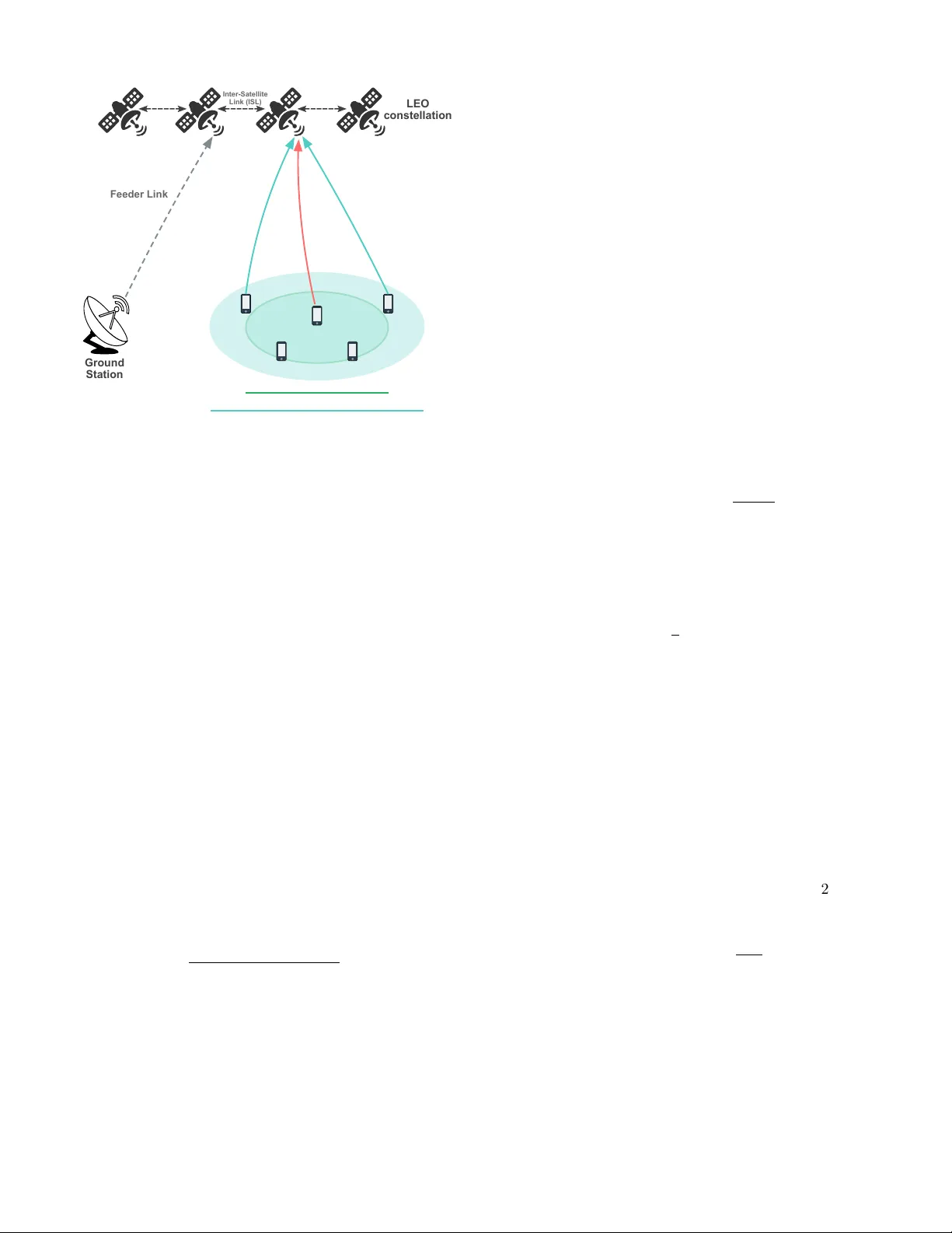
1 Elev ation-A w are Supplemen tary Uplink for Direct Satellite-to-Device Comm unications Ra jan Shrestha , Graduate Studen t Mem b er, IEEE, and Ha yder Al-Hraisha wi , Senior Mem b er, IEEE Abstract—Direct satellite-to-device (DS2D) communication enables standard mobile devices to connect directly to low Earth orbit (LEO) satellites, pro viding global cov erage without reliance on terrestrial infrastructure. How ever, the DS2D uplink is fundamen tally constrained by long propagation distances, sev ere path loss, and stringent user equipmen t (UE) pow er limits, making uplink reliability particularly c hallenging at lo w elev ation angles and beam edges. This paper inv estigates the in- tegration of supplemen tary uplink (SUL) technology into DS2D systems to enhance uplink robustness while preserving UE p o w er eciency . Lev eraging the predictable geometry of LEO satellite orbits, we develop an elev ation-aw are SUL framew ork that adapts uplink operation across frequency bands based on elev ation-dependent link margin estimates. The prop osed approac h sc hedules the UE to transmit on either a primary uplink carrier or a lo wer-frequency SUL carrier. An elev ation- a ware SUL activ ation algorithm wit h hysteresis is introduced to guide uplink carrier selection while preven ting frequen t switc hing. Simulation results demonstrate that the proposed SUL framework extends eective uplink co verage tow ard lo w- elev ation and b eam-edge regions, improv es uplink av ailabilit y o ver a satellite pass, and achiev es stable operation with a minimal num b er of uplink transitions under realistic UE p o w er constrain ts. Index T erms—Direct satellite-to-device (DS2D), supplemen- tary uplink (SUL), low Earth orbit (LEO) satellites, non- terrestrial net works (NTNs), elev ation-a w are carrier selection, geometry-a ware switching, link margin adaptation. I. In troduction Direct satellite-to-device (DS2D) comm unication is emerging as a transformativ e tec hnology for global con- nectivit y , enabling standard mobile devices to comm u- nicate directly with lo w Earth orbit (LEO) satellites without reliance on terrestrial infrastructure. This ca- pabilit y enhances service con tinuit y and resilience for handheld devices across diverse scenarios, including re- mote, maritime, and aeronautical environmen ts [ 1 ]. Recent commercial deplo ymen ts b y Starlink, AST SpaceMobile, and Lynk Global demonstrate the practical viability of this paradigm, with sev eral smartphone manufacturers announcing DS2D-capable devices for emergency and extended-co v erage connectivity services [ 2 ]. Ho w ev er, DS2D uplink transmission faces fundamen tal radio-frequency (RF) challenges. The long propagation distances to LEO satellites (slant ranges of approximately 600–2000 km), combined with severe free-space path loss The authors are with the Department of Electrical Engineering, Universit y of South Florida, T ampa, FL 33620 USA (email: ra jan- shrestha@usf.edu; hayder@usf.edu). Corresp onding author: Hayder Al-Hraishawi. (on the order of 160–190 dB), atmospheric attenuation, and stringen t user equipmen t (UE) pow er constrain ts (t ypically limited to 23 dBm), create a critical b ottleneck [3]. Unlike conv entional satellite terminals equipped with high-gain directional an tennas and high-p o w er ampliers, DS2D relies on omnidirectional smartphone an tennas with limited transmit p o w er, making reliable uplink transmis- sion particularly challenging near b eam edges and at low elev ation angles [ 4 ]. Moreo v er, higher-frequency bands (e.g., Ku/Ka-band), while oering larger bandwidths, suer from increased path loss and rain attenuation, and the high orbital velocity of LEO satellites (approximately 7.5 km/s) introduces substan tial Doppler shifts that scale linearly with carrier frequency [ 5 ]. T o address these uplink limitations, this pap er in vesti- gates the integration of supplementary uplink (SUL) tec h- nology in to DS2D systems. Originally introduced in the 3rd Generation Partnership Project (3GPP) Release 15 sp ecications for terrestrial 5G net w orks [ 6 ], SUL allo ws the netw ork to congure a UE with b oth a primary uplink (PUL) carrier, t ypically op erating at a higher frequency for improv ed sp ectral eciency , and an SUL carrier at a low er frequency to enhance co v erage and reliabilit y [7]. In the DS2D context, SUL exploits low er-frequency uplink bands (e.g., L- or S-band, 1–4 GHz) to benet from more fa vorable propagation conditions, including reduced path loss and improv ed robustness to shadowing and atmospheric attenuation. As a result, SUL can sustain reliable uplink transmission at low elev ation angles and near b eam edges when the high-frequency PUL is unable to satisfy the target signal-to-noise ratio (SNR). Unlik e carrier aggregation or multi-connectivit y tech- niques that rely on sim ultaneous multi-carrier transmis- sion [ 8 ], [ 9 ], the prop osed framework sc hedules uplink transmission on either the PUL or the SUL carrier at an y given time, thereb y av oiding concurrent transmis- sions. This either-or op eration prev ents ov erlapping uplink signaling, ensuring compliance with UE transmit p o w er constrain ts and simplifying RF fron t-end design, while still enabling seamless uplink cov erage extension. This pap er mak es the following contributions: • W e propose an elev ation-aw are SUL activ ation al- gorithm that exploits the deterministic geometry of LEO orbits to switch uplink carriers based on predicted link margin, while incorp orating hysteresis to prev ent frequent carrier switching. • Through p erformance ev aluation under representativ e DS2D scenarios, w e demonstrate that SUL substan- Primary Uplink (Ka-band) SUL Coverage (L-band) Beam Center Beam Edge Beam Edge PUL (30 GHz) SUL (1.6 GHz) LEO constellation Inter-Satellite Link (ISL) Feeder Link Ground Station Figure 1. Schematic diagram of a LEO-based DS2D system showing PUL and SUL coverage fo otprints. tially extends eective uplink cov erage and improv es uplink av ailabilit y at low elev ation angles, while pre- serving UE p ow er constraints with minimal switching o v erhead. The remainder of this paper is organized as follows: Section I I presen ts the system mo del and link budget analysis. Section II I describ es the prop osed framework with the SUL activ ation algorithm. Section IV ev aluates p erformance through simulation, and Section V concludes the pap er. I I. System Mo del W e consider the DS2D uplink from ground UEs to a constellation of LEO satellites equipped with regenera- tiv e payloads p erforming onboard baseband pro cessing and forming multiple b eams ov er the Earth’s surface [10]. Let U = { u 1 , . . . , u M } denote the set of UEs and S = { s 1 , . . . , s N } the set of satellites. Each UE maintains an uplink connection to a serving satellite using either a PUL carrier at frequency f p or an SUL carrier at frequency f s , with f s < f p , where the low er-frequency SUL improv es uplink cov erage and reliabilit y under pow er-limited UE constrain ts. The LEO satellites operate at altitudes h abov e the Earth’s surface. F or a UE at elev ation angle θ , the slan t range b et w een the UE and the satellite is d ( θ ) = q ( R E + h ) 2 − R 2 E cos 2 θ − R E sin θ , (1) where R E = 6371 km is the Earth’s radius. F or a represen tativ e LEO altitude of h = 600 km, the slant range v aries from 600 km at zenith to appro ximately 1930 km at a minim um elev ation angle of 10 ◦ [11]. A. Uplink Channel Model The DS2D uplink c hannel is dominated by line-of- sigh t (LoS) propagation, with frequency-dep endent free- space path loss and atmospheric attenuation. The receiv ed uplink p ow er at the satellite, expressed in dBm, is mo deled as P r ( f , θ ) = P t + G UE + G sat ( θ ) − P L FS ( f , d ) − L atm ( f , θ ) − L impl , (2) where f ∈ { f p , f s } denotes the uplink carrier frequency corresp onding to the PUL and SUL, resp ectively . Here, P t is the UE transmit p o w er (dBm), G UE and G sat ( θ ) denote the UE and satellite an tenna gains (dBi), and L impl accoun ts for implemen tation losses (dB) suc h as trac king and p olarization mismatc h. Sp ecically , the free- space path loss is given by P L FS ( f , d ) = 32 . 45 + 20 log 10 ( f MHz ) + 20 log 10 ( d km ) , (3) where f MHz and d km denote the carrier frequency and slan t range in MHz and kilometers, respectively . The atmospheric loss term L atm ( f , θ ) accounts for gaseous absorption and rain atten uation, which increase with carrier frequency and decreasing elev ation angle, following established ITU-R propagation mo dels [12], [13]. The satellite an tenna gain v aries with o-nadir angle according to G sat ( θ ) = G sat , max − 12 θ off ( θ ) θ 3dB 2 , (4) where θ off ( θ ) is the o-b oresight angle corresponding to elev ation angle θ , θ 3dB is the 3-dB b eamwidth, and G sat , max is the p eak antenna gain. Due to the high orbital velocity of LEO satellites, the uplink signal exp eriences a Doppler shift given by f D = v c f cos ϕ, (5) where v ≈ 7 . 5 km/s is the satellite v elo city , c is the speed of ligh t, and ϕ denotes the angle b et w een the satellite ve- lo cit y vector and the LoS direction. The resulting Doppler shift scales linearly with carrier frequency , reac hing up to tens of kHz at L/S-band and sev eral hundred kHz at Ka- band, thereby imposing increasingly stringen t frequency trac king requirements at higher frequencies. B. Uplink SNR The uplink SNR at the satellite receiver is given by SNR ( dB ) = P r ( f , θ ) − ( N 0 + 10 log 10 ( B )) , (6) where P r ( f , θ ) is the received pow er dened in ( 2 ), B is the channel bandwidth (Hz), and N 0 is the noise p ow er sp ectral densit y (dBm/Hz), computed as N 0 = − 174 + 10 log 10 T sys 290 . (7) Here, T sys denotes the satellite receiv er system noise temp erature, accoun ting for b oth antenna and receiv er noise. I I I. Proposed SUL F ramework In LEO constellations, satellite motion and orbital geometry are highly predictable. Satellite ephemeris in- formation enables accurate estimation of the UE ele- v ation angle, from which k ey channel parameters suc h as slant range, free-space path loss, and Doppler shift T able I Simulation Parameters for DS2D Uplink Ev aluation Parameter SUL (L-band) PUL (Ka-band) Carrier frequency 1.6 GHz 30 GHz UE transmit pow er 23 dBm 23 dBm UE an tenna gain 0 dBi 0 dBi Satellite an tenna gain 45 dBi 65 dBi Minimum elev ation angle 10 ◦ 10 ◦ System noise temperature 290 K 500 K Uplink bandwidth 10 MHz 10 MHz Atmospheric loss 1 dB 15 dB Implementation loss 2 dB 2 dB can b e inferred. Th us, uplink channel quality can be an ticipated as a deterministic function of elev ation angle, enabling geometry-aw are uplink adaptation. Building on this observ ation, this section presents an SUL framew ork for DS2D communications that adapts uplink operation across frequency bands based on satellite geometry to sustain reliable uplink p erformance for pow er-limited UEs. The key enabler of the prop osed framew ork is an elev ation- a w are uplink carrier selection strategy that uses predicted link margin estimates to guide switc hing b et w een PUL and SUL operation. A t an y given time, the UE is scheduled to transmit on either the PUL or the SUL, but not b oth sim ultaneously , preserving UE p ow er eciency and simplifying RF front-end design. Let the predicted uplink SNR on carrier f ∈ { f p , f s } b e [ SNR f ( θ ) = P t + G U E + G sat ( θ ) − P L F S ( f , d ( θ )) − b L atm ( f , θ ) − N 0 − 10 log 10 ( B ) − L impl , (8) where d ( θ ) follows the slan t-range mo del in ( 1 ), b L atm ( f , θ ) denotes a nominal atmospheric and rain atten uation mo del, and G sat ( θ ) captures b eam-edge gain reduction. The corresp onding predicted link margin is dened as c M f ( θ ) = [ SNR f ( θ ) − SNR req , (9) where SNR req is the minim um SNR required for reliable uplink transmission. Based on these margin estimates, an elev ation-a w are SUL activ ation algorithm is developed to adapt uplink op eration, as summarized in Algorithm 1 . The algorithm incorp orates a safet y margin ∆ s to absorb modeling uncertain ties (e.g., atmospheric v ariability and b eam-edge eects) and a hysteresis margin ∆ h to preven t frequent or oscillatory carrier switc hing. This design enables robust DS2D uplink op eration across the satellite pass while resp ecting UE p ow er and hardware constraints. IV. P erformance Ev aluation In this section, we ev aluate the p erformance of the prop osed elev ation-a w are SUL algorithm under DS2D op- erating conditions. The ob jective is to quantify the uplink robustness and cov erage gains enabled by SUL relative to PUL-only op eration. W e consider a LEO satellite at an altitude of h = 600 km serving ground UEs ov er a satellite pass, with a maxim um UE transmit pow er of 23 dBm. Algorithm 1 Elev ation-A ware SUL Activ ation for DS2D Require: Estimated elev ation angle θ (from satellite ephemeris) Require: Curren t carrier C active ∈ { PUL , SUL } Require: Thresholds: safety margin ∆ s (dB), hysteresis margin ∆ h (dB) Require: Required SNR: SNR req 1: Compute predicted margins c M p ( θ ) and c M s ( θ ) 2: if C active = PUL then 3: if c M p ( θ ) < ∆ s and c M s ( θ ) > 0 then 4: C new ← SUL 5: else 6: C new ← PUL 7: end if 8: else if C active = SUL then 9: if c M p ( θ ) > ∆ s + ∆ h then 10: C new ← PUL 11: else 12: C new ← SUL 13: end if 14: end if 15: if C new = C active then 16: Execute carrier switch and up date conguration 17: C active ← C new 18: end if 19: return C active Required SNR (dB) -5 0 5 10 15 Minimum Elevation Angle (degrees) 10 20 30 40 50 60 70 80 90 PUL-only (Ka-band, 30 GHz) SUL-enabled (Proposed) Figure 2. Minimum elevation angle required versus target SNR. The uplink bandwidth is xed at 10 MHz for b oth the PUL and SUL carriers. The PUL operates in the Ka- band (30 GHz), while the SUL op erates in the L-band (1.6 GHz). Satellite antenna gains, atmospheric losses, and system noise temperatures follo w the parameters summarized in T able I . UE elev ation angles v ary from 10 ◦ to 90 ◦ o v er the satellite pass. Fig. 2 shows the minim um elev ation angle required to sustain uplink communication as a function of the target SNR. Under PUL-only operation, the required elev ation increases rapidly with the SNR target, leading to a pronounced loss of uplink co v erage. In con trast, the prop osed SUL-enabled framework maintains connectivity Elevation Angle (degrees) 10 20 30 40 50 60 70 80 90 Uplink Availability (CDF) 0 0.2 0.4 0.6 0.8 1 PUL-only (Ka-band) SUL-enabled (Proposed) Figure 3. CDF of DS2D uplink av ailabilit y v ersus elev ation angle. at substantially low er elev ation angles across a wide range of SNR requirements. F or mo derate SNR targets (e.g., 0 – 5 dB), SUL enables uplink op eration close to the minim um elev ation limit of the satellite fo otprint (around 10 ◦ ), whereas PUL-only op eration requires elev ations ab ov e 30 ◦ – 40 ◦ . This corresp onds to an elev ation cov erage ex- tension exceeding 20 ◦ , demonstrating the eectiveness of SUL in supporting uplink communication near b eam edges and at low elev ations. Fig. 3 further quanties this gain by sho wing the CDF of uplink av ailabilit y across elev ation angles. With SUL enabled, uplink connectivity is a v ailable from the lo w est considered elev ation angles, resulting in a near- uniform accum ulation of a v ailability across the satellite pass. In contrast, PUL-only operation exhibits a delay ed onset of av ailability , becoming viable only at higher elev ations where path loss and atmospheric attenuation are suciently reduced. Thus, the SUL-enabled framework substan tially increases uplink av ailability across elev ation angles, complemen ting the spatial co v erage gains observ ed in Fig. 2 . Finally , w e ev aluate the stabilit y of the prop osed SUL framew ork b y examining the n um b er of uplink carrier switc hes during a satellite pass. Fig. 4 shows the num b er of uplink carrier switches p er pass as a function of the h ysteresis margin ∆ h . F or small h ysteresis margins, the uplink may sw itc h multiple times b et w een PUL and SUL as the predicted link margin uctuates around the switch- ing threshold. How ever, once the hysteresis margin exceeds appro ximately 3 . 5 dB, the prop osed SUL framework consisten tly requires only a single uplink transition p er satellite pass. This b ehavior demonstrates stable carrier selection and eectively eliminates ping-p ong switc hing, conrming that the prop osed geometry-a ware hysteresis mec hanism achiev es a fav orable tradeo b etw een uplink robustness and switching stability . V. Conclusion This pap er prop osed an SUL framework for DS2D com- m unications aimed at improving uplink robustness under Hysteresis Margin ∆ h (dB) 0 1 2 3 4 5 6 Number of Uplink Switches per Pass 0 0.5 1 1.5 2 2.5 3 Figure 4. Number of uplink carrier switches p er satellite pass versus hysteresis margin. lo w-elev ation and b eam-edge op erating conditions. By lev eraging a low er-frequency SUL carrier in conjunction with a geometry-aw are switching mechanism, the prop osed framew ork mitigates the severe path loss and atmospheric atten uation limitations inherent to high-frequency PUL op eration. Simulation results demonstrated that the SUL- enabled scheme substan tially extends the eectiv e up- link cov erage region compared to PUL-only op eration, enabling reliable communication at low er elev ation angles across a wide range of SNR requiremen ts. The proposed approac h also signicantly increases uplink av ailability o v er a satellite pass, impro ving connectivit y from early visibilit y p oints without violating UE p o w er constraints. Ov erall, these results highligh t SUL as a practical and lo w-complexit y enhancemen t for DS2D uplink design, particularly in challenging propagation environmen ts. References [1] D. T uzi, T. Delamotte, and A. Knopp, “Satellite swarm-based antenna arra ys for 6G direct-to-cell connectivity ,” IEEE Access, vol. 11, pp. 36 907–36 928, 2023. [2] J. Garcia-Cabeza et al., “Direct-to-cell: A rst lo ok into star- link’s direct satellite-to-device radio access netw ork through crowdsourced measurements,” IEEE Commun. Mag., pp. 1–7, 2025. [3] Z. M. Bakhsh et al., “Multi-satellite MIMO systems for direct satellite-to-device communications: A surv ey ,” IEEE Commun. Surveys T uts., v ol. 27, no. 3, pp. 1536–1564, 2025. [4] Z. Xu, G. Chen, R. F ernandez, Y. Gao, and R. T afazolli, “En- hancement of direct LEO satellite-to-smartphone communica- tions by distributed b eamforming,” IEEE T rans. V eh. T echnol., vol. 73, no. 8, pp. 11 543–11 555, 2024. [5] H. Al-Hraishawi, H. Chougrani, S. Kissele, E. Lagunas, and S. Chatzinotas, “A survey on nongeostationary satellite systems: The communication p erspective,” IEEE Commun. Surv eys T uts., vol. 25, no. 1, pp. 101–132, Aug. 2023. [6] 3GPP TS 38.101-1 V18.5.0, “3rd Generation Partnership Project; T echnical Sp ecication Group Radio Access Netw ork; NR; User Equipmen t (UE) radio transmission and reception; Part 1: Range 1 Standalone (Release 15),” 3rd Generation Partnership Pro ject, T ech. Rep., 2018. [7] F. Rinaldi, A. Raschella, and S. Pizzi, “5G NR system design: A concise surv ey of key features and capabilities,” Wireless Netw orks, vol. 27, no. 8, pp. 5173–5188, 2021. [8] M. G. Kibria, H. Al-Hraishawi, E. Lagunas, S. Chatzinotas, and B. Ottersten, “Joint b eam hopping and carrier aggregation in high throughput multibeam satellite systems,” IEEE Access, vol. 10, pp. 122 125–122 135, 2022. [9] T. Ma, J. Chen, Y. Xu, H. Zhou, and J. Li, “Leveraging decou- pling m ulti-connectivity for direct satellite-to-device comm uni- cations in 6g: Architecture, technologies, and opportunities,” IEEE Comm un. Mag., v ol. 63, no. 11, pp. 45–52, 2025. [10] 3GPP TR 38.811V15.1.0, “3rd Generation Partnership Pro ject; T echnical Sp ecication Group Radio Access Network; Study on New Radio (NR) to supp ort Non T errestrial Netw orks (Release 15),” 3rd Generation P artnership Project, T ech. Rep., 2019. [11] R. W ang, M. A. Kishk, and M.-S. Alouini, “Mo deling and analysis of non-terrestrial netw orks by spherical sto chastic geometry: A survey ,” IEEE Comm un. Surveys T uts., vol. 28, pp. 1879–1905, 2026. [12] ITU-R, “Atten uation by Atmospheric Gases and Related Ef- fects,” International T elecommunication Union Radiocommu- nication Sector, Recommendation P .676, August 2019. [13] ITU-R, “Propagation Data and Prediction Metho ds Required for the Design of Earth-Space T elecomm unication Systems,” International T elecommunication Union Radiocommunication Sector, Recommendation P .618, July 2017.
Original Paper
Loading high-quality paper...
Comments & Academic Discussion
Loading comments...
Leave a Comment