Downlink Beamforming Design for NOMA Using Convolutional Neural Networks
Non-orthogonal multiple access (NOMA) and beamforming are well-established techniques for enabling massive connectivity in future wireless networks. However, many optimal beamforming solutions rely on highly complex iterative algorithms and optimizat…
Authors: Chentong Li, Saeed Mohammadzadeh, Kanapathippillai Cumanan
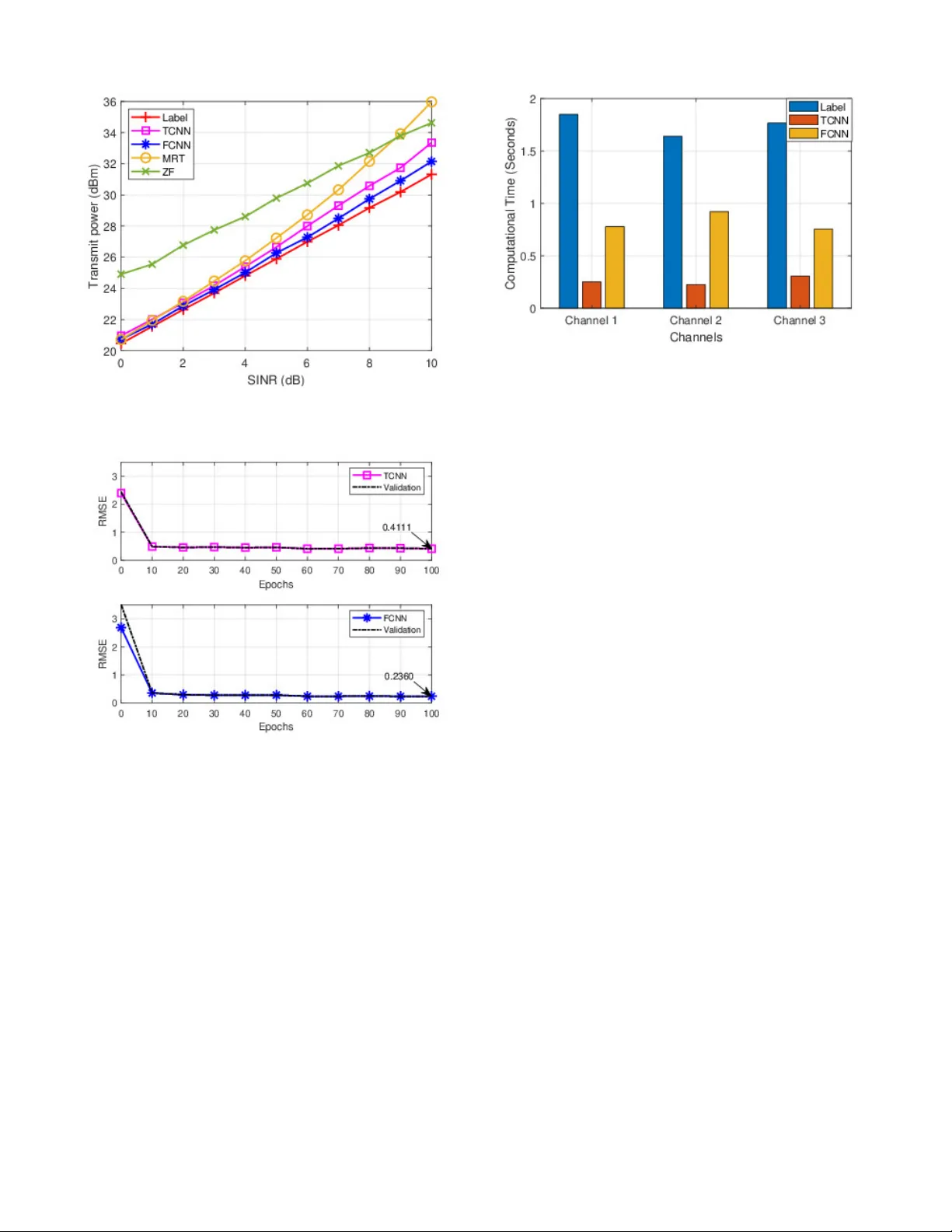
Do wnlink Beamforming Design for NOMA Using Con v olutional Neural Networks Chentong Li * , Saeed Mohammadzadeh * , Kanapathippillai Cumanan * , Octavia A. Dobre † , * School of Physics Engineering and T echnology - University of Y ork, Y ork, United Kingdom † Department of Electrical and Computer Engineering, Memorial Univ ersity , St. John’ s NL A1B, Canada cl2215@y ork . ac . uk * , saeed . mohammadzadeh@y ork . ac . uk * , k anapathippillai . cumanan@york . ac . uk * , o dobre@m un . ca † Abstract —Non-orthogonal multiple access (NOMA) and beamforming are well-established techniques for enabling mas- sive connectivity in future wireless networks. However , many optimal beamf orming solutions r ely on highly complex iterati ve algorithms and optimization methods, resulting in an increase in computational burden and latency , making them less suitable for delay-sensitive applications and services. T o address these challenges, we pr opose an effective con volutional neural network (CNN)-based approach f or beamforming design in downlink NOMA systems to solve the transmit power minimization problem. The proposed method utilizes two representations of channel state information as input features to pr oduce normalized beamforming vectors. Simulation results show that the CNN-based solution closely approximates the optimal label performance while significantly reducing computational time compared to con ventional high-complexity algorithms, enhanc- ing its practicality f or real-time applications. Index T erms —Beamforming, conv olutional neural network, non-orthogonal multiple access, power minimization. I . I N T R O D U C T I O N Future wireless communication systems will form a hyper - connected society with unpredictable massiv e numbers of users and de vices. Higher data speeds, reduced latency , in- creased dependability , e xtensiv e connection, and increased energy economy are the motiv ating factors behind these systems [1]. Traditional orthogonal multiple access (OMA) technologies will not be able to meet the rapidly increasing demands of communication users, especially with the increase in the Internet of Things (IoT) devices [2], which pose a substantial challenge in ensuring massi ve connectivity in 6G and beyond. T o address these challenges and meet such unprecedented requirements, non-orthogonal multiple access (NOMA) has emerged as a viable solution by introducing additional degrees of freedom (DoF) in the power domain, enabling non-orthogonal radio resource sharing among users simultaneously [2], [3]. Compared to the traditional OMA, which allocates separate time or frequency resources to individual users, NOMA enables users to share these resources simultaneously using The work of S. Mohammadzadeh and K. Cumanan were supported by the UK Engineering and Physical Sciences Research Council (EPSRC) under grant number EP/X01309X/1. The work of O. A. Dobre was supported in part by the Canada Research Chairs Program CRC-2022-00187 and the NSERC Discovery grant RGPIN- 2019-04123. different power levels, known as power -domain NOMA [4], [5]. In other words, the base station (BS) in a downlink NOMA system sends a superposition signal to each user with different power lev els. Users with better channel conditions or those closer to the BS first decode the signal transmitted to users with worse channel conditions or those farther from the BS, subtract that signal from the received signal, and then decode their signal. Meanwhile, the user with the worst channel condition or farther from the BS treats signals intended for other users as interference and decodes their signal directly . This decoding process for users is kno wn as successi ve interference cancellation (SIC). T o facilitate a successful implementation of SIC and maintain fairness, users with poorer conditions are allocated higher power levels to mitigate interference from other users [1], [6]. At the same time, integrating beamforming techniques into NOMA systems has been proven to be advantageous, as beamforming enhances signal reception and transmission by directing signals toward the intended users, thus improving the quality of the recei ved signals [7]–[9]. In [10], a beam- forming technique is proposed to minimize transmit power and improve network energy efficienc y while using NOMA to mitigate interference, thus reducing total transmit power . Furthermore, the work in [11] proposes a three-step resource allocation framew ork dev eloped to optimize beamforming in NOMA systems. Howe ver , these optimization processes, which depend on mathematical models or toolboxes, can become complex and lead to significant computational delays as the number of users in the wireless network increases. Hence, deep learning-based techniques, especially the con- volutional neural network (CNN), hav e been seen as a po- tential solution to these highly complex problems in mathe- matical modeling, since it could extract significant features to produce the intended output automatically [12]. The power allocation problem with NOMA is addressed by the authors in [13], where a CNN is created with channel data as input, while its outputs are the po wer . Similarly , in [14], a CNN is proposed to generate uplink power , follo wed by an algorithm to compute downlink power suitable for real-time applications. Furthermore, in [15], deep CNNs are employed to directly generate beamforming vectors for each user , enhancing performance gains and facilitating large-scale deployment in underwater communication networks. Motiv ated by the aforementioned work, this paper proposes a CNN-based beamforming method to address the transmit power minimization problem in downlink NOMA systems. The model is trained to map the channel information to the corresponding beamforming vectors, eliminating the need for iterativ e optimization during inference. Once trained, the model requires only the channel as input to generate beam- forming vectors, thereby significantly reducing computational complexity and execution time compared to conv entional optimization and iteration based approaches. This efficienc y makes the proposed method well suited for real-time and practical scenarios. Notations: W e use lowercase and uppercase boldface letters for vectors and matrices, respectiv ely . E {·} stands for the statistical expectation. The set of real numbers is represented by the symbol R , while the complex numbers are denoted by the symbol C . ( · ) H denotes the conjugate transpose of the vectors or matrix. The Euclidean norm of a vector is represented by the symbol ∥ · ∥ 2 . ℜ ( · ) and ℑ ( · ) are the real and imaginary parts of a complex number, respectiv ely . I I . S Y S T E M M O D E L A N D P RO B L E M F O R M U L AT I O N W e consider a do wnlink transmission of the NOMA system, where the BS equipped with N antennas serves K single- antenna users, indexed by the set K = { 1 , · · · , K } . It is assumed that the BS has perfect channel state information (CSI). Therefore, the signal recei ved by each user k is given as: y k = h H k x + n k , ∀ k ∈ K , (1) where h k ∈ C N × 1 represents the channel vectors between the BS and the user k . The BS simultaneously transmits a superimposed signal of the form x = P k ∈K √ p k u k s k , where p k denotes the transmitted power allocated to the user k . u k ∈ C N × 1 is the beamforming vector designed for the user k , where it has ∥ u k ∥ 2 = 1 , and s k is the information signal intended for the user k (assuming that E {| s k | 2 } = 1 ). The noise term n k is modeled as a zero-mean circularly symmetric complex Gaussian random variable with variance σ 2 . Users are ordered based on their channel strength, such that ∥ h 1 ∥ 2 ≤ ∥ h 2 ∥ 2 ≤ · · · ≤ ∥ h K ∥ 2 . For the successful implementation of SIC on users, it is crucial to allocate higher power levels to users with weaker channel conditions. This ensures that their signals are sufficiently strong to be accurately distinguished and decoded. Subsequently , these decoded signals can be subtracted from the receiv ed signal in users with better channel conditions, facilitating effecti ve interference cancellation [16]. In other w ords, the user k can decode and subtract the signals of the first ( k − 1) users. This can be achiev ed by ensuring compliance with the following constraints, which must be met to guarantee the desired performance [17]: p 1 | h H k u 1 | 2 ≥ · · · ≥ p k | h H k u k | 2 ≥ · · · ≥ p K | h H k u K | 2 , ∀ k ∈ K (2) In order to measure the quality of service for the user k , let us define the signal-to-interference-and-noise ratio (SINR) as follows: SINR k = p k | h H k u k | 2 K P i = k +1 p i | h H k u i | 2 + σ 2 . (3) T o facilitate the solution, we introduce a ne w variable defined as w k = √ p k u k . This reformulation allows the original SINR expression in (3) to be rewritten as follows: SINR k = | h H k w k | 2 K P i = k +1 | h H k w i | 2 + σ 2 . (4) Hence, the power minimization problem is defined as: min w k ∈ C N × 1 K X k =1 ∥ w k ∥ 2 2 (5a) s.t. | h H k w k | 2 P K i = k +1 | h H k w i | 2 + σ 2 ≥ γ min k , ∀ k ∈ K , (5b) where γ min k represent the minimum SINR threshold. The original power minimization problem formulated in (5) is inherently non-con vex due to the non-con vex nature of the SINR constraints in (5b). T o address this challenge, we reformulate the problem using second-order cone program- ming, which transforms the non-conv ex formulation into a con vex optimization problem. This reformulation enables the computation of the optimal solution efficiently [16], [17]. In this design, a phase rotation is applied to the beamform- ing vectors without affecting the SINR and still achiev es the same solutions. This is due to the fact that the SINR values depend on the magnitude of the h H k w k terms and not on the phase of h H k w k [18]. In other words, it allo ws us to assume that h H k w k contains only the real part, effecti vely treating the imaginary part as zero, which, in turn, makes the square root of | h H k w k | 2 well defined [8], [19]. Thus, the original non- con vex constraints can be transformed into a second-order cone (SOC) and linear constraints by applying the square root to (5b), as shown below: γ min k ( K X i = k +1 | h H k w i | 2 + σ 2 ) ≤ | h H k w k | 2 ⇐ ⇒ q γ min k | h H k w k +1 | . . . | h H k w K | σ ≤ | h H k w k | , ℑ ( h H k w k ) = 0 , ∀ k ∈ K . (6) Therefore, the optimization problem in (5) can be written in an easier and more tractable format using (6), allo wing us to reformulate it as follows: min w k ∈ C N × 1 K X k =1 || w k || 2 2 s.t. q γ min k | h H k w k +1 | . . . | h H k w K | σ ≤ | h H k w k | , ℑ ( h H k w k ) = 0 , ∀ k ∈ K . (7) Although some optimization toolboxes can ef ficiently solve the problem in (7), their computational time may be pro- hibitiv e when fast and reliable service is essential in the future. Hence, we introduce a CNN-based method, which con- siders the channel as an input and generates the beamforming vector u k , to achieve a near-optimal solution and to facilitate practical applicability . Note that to generate labeled input and output pairs for CNN training, we solve the optimization problem in (7) with the optimization toolbox, such as the CVX toolbox. Furthermore, to verify whether CNN-generated beamform- ing vectors u k satisfy the SINR requirements and minimize total transmit power , we consider the following ev aluation approach [14]. Gi ven the original e xpression of SINR in (3), it is necessary to determine the corresponding transmit po wer p k to calculate the SINR for each user . Accordingly , the do wnlink power allocation p can be obtained as follows: p = σ 2 Ψ − 1 1 , (8) where 1 = [1 , . . . , 1] T , and Ψ ∈ C K × K is giv en as: [ Ψ ] ki = 1 γ min k h H k u k 2 , if k = i, − h H k u k 2 , if k < i, 0 , else. (9) I I I . T H E C N N - B A S E D B E A M F O R M I N G M E T H O D For CNN-based methods, we propose two different input matrix formats and reconstruct the channel to ensure com- patibility with CNN model, thus achieving more efficient feature extraction and learning. W e then provide a detailed explanation of the architecture and functionality of each layer within the CNN. Finally , we describe the training and testing configurations, along with the implementation details of the proposed network in MA TLAB deep learning toolbox. A. Pr oposed CNN F ramework The architecture of the proposed CNN model is illustrated in Fig. 1. The network begins with an input layer , follo wed by a sequence of con volutional blocks. Each block consists of a conv olutional layer , a batch normalization layer, and an activ ation function. After multiple such blocks, the network includes a mean pooling layer and a fully connected layer . Finally , a regression layer produces the CNN output. Fig. 1. The architecture of the proposed CNN Since both channel and beamforming data consist of the complex values (real and imaginary components), and due to limitations in the MA TLAB deep learning toolbox, which primarily supports real valued inputs, it is necessary to transform these datasets into alternativ e real valued formats for network training. Note that we discuss the parameters in the MA TLAB toolbox and the size of the input matrix for this layer in Section III-B. The first layer of the proposed CNN architecture is the input layer, where the channel is used as label input. Here, we introduce two different input matrix formats, each designed to reorganize the channel in a specific way and then rebuild it into matrix form. For the first input matrix method, the channel h = [ h T 1 , . . . , h T K ] is separated into its real and imaginary components as follows: TCNN: ℜ ( h ) = [ real ( h T 1 ) , . . . , real ( h T K )] ∈ R 1 × ( N K ) , ℑ ( h ) = [ imag ( h T 1 ) , . . . , imag ( h T K )] ∈ R 1 × ( N K ) , (10) where we refer to this model as the TCNN, where the complex channel undergoes an I/Q transformation as described in [9]. Specifically , the input to the con volutional layer is reshaped as [ ℜ ( h ); ℑ ( h )] ∈ R 2 × N K . Ho wev er, this transformation treats each user’ s channel independently , which can limit the ability of the model to capture spatial or inter-user relationships. As the complexity of the output data increases, effecti vely mod- eling the dependencies between users becomes increasingly important to improv e the CNN prediction accuracy . Therefore, we propose to reshape the channel into an alternativ e format to enhance the interdependence between channel elements and thus improve the reliability of the CNN output. W e construct the channel matrix as H = [ h 1 , . . . , h K ] ∈ C N × K , and extract the real and imaginary components as follows: FCNN: ℜ ( H ) = real ( H ) ∈ R N × K , ℑ ( H ) = imag ( H ) ∈ R N × K , (11) where we call the FCNN. Then we reshape it into a new input matrix, which is given as [ ℜ ( H ) , −ℑ ( H ); ℑ ( H ) , ℜ ( H )] ∈ R 2 N × 2 K . This approach ensures that more components can interact through con volution, allowing the CNN to extract more information from the input matrix. Both input formats restructure the channel to suit the training requirements of the CNN better . Ho wever , when considering the NOMA scenario, where channels are ordered according to their quality , there is an inherent correlation within the channel coefficients. The input format in (11) is specifically designed to enhance and preserv e these inter- channel relationships, providing the CNN with a better oppor- tunity to learn the underlying structure across input elements. Furthermore, (11) employs a square matrix structure, which aligns with the square filter sizes used in the con volution and mean pooling layers. This design not only retains more spatial information but also enables more effecti ve feature extraction compared to the simpler format in (10). For the output label data, we follow a similar reshaping strategy as used for the input data. The beamforming matrix is denoted by U = [ u 1 , u 2 , . . . , u K ] ∈ C N × K , where each u k ∈ C N × 1 represents the beamforming vector corresponding to user k . For compatibility with the CNN’ s regression output, each complex beamforming vector is transformed into a real- valued linear format. Specifically , the real and imaginary parts are separated as ℜ ( u k ) ∈ R N × 1 and ℑ ( u k ) ∈ R N × 1 , respectiv ely . The final label format is constructed by stacking these components, resulting in a structured real-valued vector suitable for training. u = [ ℜ ( u 1 ); ℑ ( u 1 ); ℜ ( u 2 ); ℑ ( u 2 ); . . . , ℜ ( u K ); ℑ ( u K )] ∈ R (2 N K ) × 1 . (12) Ar chitectur e of the pr oposed framework : In the proposed framew ork, the input layer is followed by four complex con volutional blocks. For all input matrix formats, each con volutional layer employs a stride of 1 and zero padding to preserve spatial dimensions. Each layer utilizes 64 kernels of size 3 to extract critical features from the input. T o promote stable and consistent feature distrib utions, batch normalization is applied after each conv olutional layer , which accelerates con vergence and enhances overall learning efficiency during training. Next, the activ ation function layer in conv olutional blocks giv es the network nonlinearity , which helps it recognize complex patterns in the input. In contrast to the commonly used rectified linear unit (ReLU) function, which can be expressed as ReLu = max(0 , x ) , we employ the leaky ReLU function. This function enables a small, non-zero gradient for negati ve input values and is giv en as follo ws: Leaky ReLU ( x ) = ( x, x ≥ 0 , 0 . 01 x, x < 0 . (13) Follo wing the four con volutional blocks, a mean pooling layer with a kernel size of 3, zero padding, and a stride of 1 is applied to reduce the dimensionality and computational complexity of the subsequent layers. The output is then passed through a fully connected layer , which transforms the feature map into an output matching the size of the labeled data. Finally , a hyperbolic tangent (T anh) acti vation function is applied to map the real-valued outputs to the range [ − 1 , 1] , ensuring consistency with the normalized label format [20]. And the form is giv en as: T anh ( x ) = sinh( x ) cosh( x ) = e x − e − x e x + e − x . (14) The final regression layer serves as the output of the network, designed to predict continuous v alues rather than discrete classes. In this work, the root mean square error (RMSE) is adopted as the loss function to guide the training process. Based on the proposed CNN architecture, the model is trained using channel data as input and the corresponding beamforming vectors as output labels, targeting the transmit power minimization problem. These labels are generated using the optimization based methodology previously de- scribed, employing a CVX toolbox to solve the underlying optimization problem. B. T raining and T esting T o train the proposed CNN model, a total of 20,000 data samples are generated for training, and an additional 5,000 samples are reserved for testing. The network is trained ov er 100 epochs using a mini batch size of 200. T o enhance generalization, the training data is randomly shuffled at the beginning of each epoch, and 20% of the training set is allocated for validation. Each conv olutional block in the CNN follows a consistent structure and parameter configuration throughout the network. The training process utilizes the Adam optimizer [21] to update the model parameters, with the RMSE employed as the loss function. The initial learning rate is set at 0.01 and is reduced by a factor of ρ = 0 . 5 after 50 epochs, that is, halfway through the training, resulting in a new learning rate of 0.005. This schedule helps stabilize con vergence and prevent overfitting during the later stages of training. The proposed CNN solution was run on a laptop equipped with an 11th Gen. Intel i5-1145G7 CPU and 16 GB of RAM and implemented in MA TLAB R2022a using the deep learning toolbox, with the network architecture reshaped to suit the toolbox’ s training requirements. I V . S I M U L A T I O N R E S U LT S W e consider a downlink transmission of a four-antenna ( N = 4 ) NOMA system in BS, which supports K = 3 single antenna users. The communication channel is characterized by Rayleigh fading. T o ensure fairness among users, all users hav e the same target SINR. The noise variance is giv en as σ 2 = 0 . 1 . W e compare the results obtained from CNN- based input methods with those obtained from the labeled data generated using an optimization toolbox. In addition, we ev aluate the performance of two con ventional beamforming techniques, maximum ratio combining (MRC) and zero- forcing (ZF), and compare their performance with the labeled result and the CNN-based method. Fig. 2 illustrates the transmit power consumption for v ary- ing SINR requirements, comparing with different methods, Fig. 2. T ransmit power performance versus different SINR thresholds Fig. 3. Learning curve of the TCNN and FCNN methods with Adam optimizer and using a test dataset of 5,000 samples, the mean total trans- mit power consumption is ev aluated and analyzed. It illus- trates that the CNN-based beamforming methods consistently achiev e a near-label solution compared to other methods. As SINR increases, CNN-based methods demonstrate more con- sistent performance across varying SINR levels, whereas the performance gap between MRC, ZF , and the optimal solution becomes more pronounced. Although MRC and ZF are widely used beamforming techniques, they require a higher transmit power to achiev e the target SINR compared to the label-based optimization results. In addition, MRC performs relatively well under low SINR requirements, but becomes inef ficient as the SINR increases, due to its high po wer demand. In contrast, ZF consistently exhibits suboptimal performance throughout the SINR range. Moreover , it is seen that when TCNN and FCNN are compared, the FCNN method outperforms TCNN, Fig. 4. Computation time of label, TCNN, and FCNN methods with the performance gap widening as the SINR increases. This indicates that FCNN remains more robust and reliable under higher SINR requirements. Because the TCNN and FCNN perform better in this problem, to compare the conv ergence speed and performance of the two input matrices, we analyze the maximum number of epochs and their RMSE metrics. Both input matrices are trained under a SINR threshold of 5dB, using the same training and testing data, as illustrated in Fig. 3. The re- sults demonstrate that both CNN-based beamforming methods con verge toward their validation values in the maximum epochs, indicating that neither of the models exhibits signs of overfitting. Although both methods demonstrate relativ ely low RMSE within the first 10 epochs, additional training epochs are necessary to allow the network to further adjust its weights and effecti vely learn the features from the input data. Furthermore, the RMSE comparison at conv ergence shows that the RMSE of FCNN is lower than that of TCNN, indicating that the performance of FCNN is superior . T o e v aluate the time consumption of the proposed methods, we compare the results of the label method with fully trained TCNN and FCNN on three dif ferent channels, as summarized in Fig. 4. The results demonstrate that fully trained CNN- based beamforming methods are more suitable for real-time applications, as they achiev e significantly shorter processing times compared to the label method. This efficienc y is at- tributed to the fact that CNN-based methods use a large num- ber of input data during training to approximate near-optimal solutions. Once trained, the model can generate beamforming results without iterativ e computations, thus significantly re- ducing the ex ecution time. Furthermore, although the FCNN requires a longer training duration than the TCNN due to its more complex input matrix, both CNN-based methods substantially outperform the label-based solution in terms of computational efficienc y . V . C O N C L U S I O N In this paper , we proposed a CNN-based model to solve a power minimization problem in a downlink NOMA beam- forming system. The model is designed to generate beam- forming directly using the channel as input. T o enhance the performance of the CNN model, we explore two different input matrices: TCNN and FCNN. The result indicates that CNN-based methods outperform other beamforming methods, achieving solutions closer to the label solution method. Fur- thermore, under a given SINR threshold, the FCNN consis- tently achiev es a near-label solution and lower RMSE com- pared to the TCNN. The results considering the processing time demonstrate that the CNN-based model significantly reduces computational time while maintaining near-optimal performance. R E F E R E N C E S [1] Y . Liu, Z. Qin, M. Elkashlan, Z. Ding, A. Nallanathan, and L. Hanzo, “Nonorthogonal Multiple Access for 5G and Beyond, ” IEEE Proc. , vol. 105, no. 12, pp. 2347–2381, Nov . 2017. [2] S. M. R. Islam, N. A vazov , O. A. Dobre, and K.-s. Kwak, “Power- Domain Non-Orthogonal Multiple Access (NOMA) in 5G systems: Potentials and Challenges, ” IEEE Commun. Surve ys T uts. , vol. 19, no. 2, pp. 721–742, Oct. 2016. [3] L. Dai, B. W ang, Y . Y uan, S. Han, I. Chih-Lin, and Z. W ang, “Non- Orthogonal Multiple Access for 5G: Solutions, Challenges, Opportuni- ties, and Future Research Trends, ” IEEE Commun. Mag. , vol. 53, no. 9, pp. 74–81, Sep. 2015. [4] F . Alavi, K. Cumanan, Z. Ding, and A. G. Burr, “Robust Beamform- ing T echniques for Non-Orthogonal Multiple Access Systems with Bounded Channel Uncertainties, ” IEEE Commun. Lett. , vol. 21, no. 9, pp. 2033–2036, May . 2017. [5] M. T . Le, G. C. Ferrante, G. Caso, L. De Nardis, and M.-G. Di Benedetto, “On Information-Theoretic Limits of Code-Domain NOMA for 5G, ” IET Communications , vol. 12, no. 15, pp. 1864–1871, Sep. 2018. [6] Q. C. Li, H. Niu, A. T . Papathanassiou, and G. W u, “5G Network Capacity: Key Elements and Technologies, ” IEEE V eh. T echnol. Mag. , vol. 9, no. 1, pp. 71–78, Jan. 2014. [7] D. Lin, K. Cumanan, and Z. Ding, “Beamforming Design for BackCom Assisted NOMA Systems, ” IEEE W ir eless Commun. Lett. , vol. 12, no. 9, pp. 1494–1498, May . 2023. [8] M. Bengtsson and B. Ottersten, “Optimal Downlink Beamformingusing Semidefinite Optimization, ” in 37th Annual Allerton Conference on Communication, Contr ol, and Computing , 1999, pp. 987–996. [9] S. Mohammadzadeh, V . H. Nascimento, R. C. de Lamare, and N. Ha- jarolasvadi, “Robust Beamforming Based on Complex-Valued Con vo- lutional Neural Networks for Sensor Arrays, ” IEEE Sig. Process. Lett. , vol. 29, pp. 2108–2112, Oct. 2022. [10] A. Bindle, T . Gulati, and N. Kumar , “Energy Efficient NOMA Based Beamforming and Po wer Control Architecture for Future Communi- cation Networks, ” Physical Communication , vol. 60, p. 102127, Oct. 2023. [11] J. W ang, Y . W ang, and J. Y u, “Joint Beam-Forming, User Clustering and Power Allocation for MIMO-NOMA Systems, ” Sensors , vol. 22, no. 3, p. 1129, Feb. 2022. [12] M. Geubbelmans, A.-J. Rousseau, T . Burzykowski, and D. V alkenbor g, “ Artificial Neural Networks and Deep Learning, ” American Journal of Orthodontics and Dentofacial Orthopedics , vol. 165, no. 2, pp. 248– 251, 2024. [13] Z. Zhang, D. Zhai, R. Zhang, X. T ang, and Y . W ang, “ A Con volutional Neural Network Based Resource Management Algorithm for NOMA Enhanced D2D and Cellular Hybrid Networks, ” in 2019 11th Interna- tional Conference on W ireless Communications and Signal Pr ocessing (WCSP) . IEEE, Oct. 2019, pp. 1–6. [14] W . Xia, G. Zheng, Y . Zhu, J. Zhang, J. W ang, and A. P . Petropulu, “ A Deep Learning Framew ork for Optimization of MISO Downlink Beamforming, ” IEEE T rans. Commun. , vol. 68, no. 3, pp. 1866–1880, Dec. 2019. [15] H. Sun, X. Feng, J. W ang, M. Zhou, and X. Kuai, “Beamforming Design via Deep Learning for Underwater Acoustic Communications, ” in 2021 IEEE 21st International Conference on Communication T ech- nology (ICCT) , Oct. 2021, pp. 576–580. [16] M. F . Hanif, Z. Ding, T . Ratnarajah, and G. K. Karagiannidis, “ A Minorization-Maximization Method for Optimizing Sum Rate in the Downlink of Non-Orthogonal Multiple Access Systems, ” IEEE Tr ans. Sig. Process. , vol. 64, no. 1, pp. 76–88, Sep. 2015. [17] F . Alavi, K. Cumanan, Z. Ding, and A. G. Burr , “Beamforming T ech- niques for Nonorthogonal Multiple Access in 5G Cellular Networks, ” IEEE T rans. V eh. T echnol. , vol. 67, no. 10, pp. 9474–9487, Jul. 2018. [18] A. W iesel, Y . Eldar, and S. Shamai, “Linear Precoding via Conic Optimization for Fixed MIMO receivers, ” IEEE T rans. Sig. Pr ocess. , vol. 54, no. 1, pp. 161–176, Dec. 2005. [19] E. Bj ¨ ornson, E. Jorswieck et al. , “Optimal Resource Allocation in Coordinated Multi-cell Systems, ” F oundations and Tr ends® in Com- munications and Information Theory , vol. 9, no. 2–3, pp. 113–381, Jan. 2013. [20] P . Kim, “Matlab Deep Learning, ” W ith machine learning, neural networks and artificial intelligence , vol. 130, no. 21, 2017. [21] D. P . Kingma, “ Adam: A method for Stochastic Optimization, ” arXiv pr eprint arXiv:1412.6980 , Dec. 2014.
Original Paper
Loading high-quality paper...
Comments & Academic Discussion
Loading comments...
Leave a Comment