Channel Estimation for Double-BD-RIS-Assisted Multi-User MIMO Communication
Deploying multiple beyond diagonal reconfigurable intelligent surfaces (BD-RISs) can potentially improve the communication performance thanks to inter-element connections of each BD-RIS and inter-surface cooperative beamforming gain among BD-RISs. Ho…
Authors: Junyuan Gao, Shuowen Zhang, Liang Liu
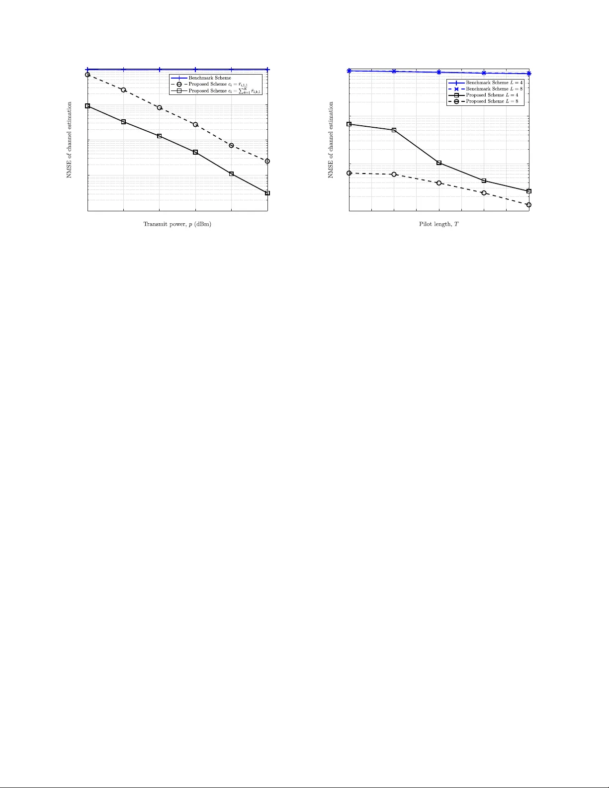
1 Channel Estimation for Double-BD-RIS-Assisted Multi-User MIMO Communication Junyuan Gao, Shu owen Zhang, and Liang Liu Abstract —Deploying multiple bey ond diagonal re confi gurable intelligent surfaces (BD-RISs) can potentially improv e the com- munication perfor mance th anks to inter -element connections of each BD-RIS and inter -surface cooperativ e beamf orming gain among BD-RISs. Ho wever , a major issue f or multi-BD-RIS- assisted communication lies in th e chann el estimation ove rh ead - the channel coefficients associated with th e off-diagonal el- ements in each BD-RIS ’ s scattering matrix as well as those associated with the reflection l inks among BD-RISs hav e to be estimated. In this paper , we propose an efficient channel estima- tion framework for double-BD-RIS -assisted multi-user multipl e- input multiple-output (MIMO) systems. Specifically , we re veal that high-dimensional cascaded chann els ar e characterized by five low-dimensional matrices by exploiting channel correlation properties. Based on this novel observ ation, in th e ideal noiseless case, we dev elop a channel estimation scheme to recov er these matrices sequentially and characterize th e closed-f orm overhead required for perfect estimation as a fu nction of the n umbers of users and each B D-RIS’ s elements and ch annel ranks, which is with the same order as th at in doubl e-d iagonal-RIS-aided com- munication systems. This exciting result impl ies th e sup eriority of cooperative BD-RIS-aided communi cation over the diagonal- RIS counterpart ev en when chann el estimation overhead is considered. W e further extend the proposed scheme to practical noisy scenarios and provide extensiv e numerical simul ations to validate its effectiveness. Index T erms —Beyo n d diagonal reconfigurable in telligent sur - face (BD-RIS), channel estimation, double-BD-RIS , low-ov erhead communication. I . I N T R O D U C T I O N A. Motivation Reconfigura ble intelligent surface (RIS) has been recog- nized as a promising techniq ue in fu tu re sixth -generatio n (6G) cellular networks. It is able to c o ntrol the radio p r opagatio n en v ir onment in fa vor of sig nal transmission, there by en hancing the wireless commu n ication p e rforman ce [1], [2]. In con - ventional RIS-aid ed commu n ication, each reflec tin g element is adjusted ind ependen tly such th at the scattering matr ix is diagona l. Howe ver , this diagon a l architecture limits th e flex- ibility in wa ve manip u lation. T o addr ess th is issue, a new technolog y , kn own as the beyond d iagonal RIS (BD-RIS), has b een p roposed an d attracted significant attentio n [3], [4]. By intro ducing inter c onnection s among reflecting elements, the scattering matrix of BD-RIS exhibits a more gener a l non-d iagonal stru cture, thereby offering g reater flexibility in wa ve ma nipulation and leading to enhance d beamformin g gain, spectral efficiency , and coverage compare d to trad itional J. Gao, S. Zhang, and L. Liu are with the Department of Electrical and Electroni c E nginee ring, T he Hong Kong Polytechnic Uni versity , Hong Kong SAR (e-mail: { junyuan.gao , s huo wen.zhang, liang-ei e.liu } @polyu.edu.hk). BD-RIS 2 BD-RIS 1 G 2 B r 2,1 User 1 User K G 1 r 1,1 r 2, K r 1, K Fig. 1. System model of double-BD-RIS-aide d communication . BD-RIS 1 is close to the users, and BD-RIS 2 is close to the BS. The BS recei ves signals via the user - BD-RIS 1 - BS link, user - BD-RIS 2 - BS link, and user - BD-RIS 1 - BD-RIS 2 - BS link. diagona l- RIS-aided comm unication. Given th e appealing po- tential o f BD-RIS, extensive intere sts have been d ev oted to this area, inc lu ding modeling and arch itecture d esign [4], [5], perfor mance optimizatio n an d beamfor ming design [6], [7], channel estimation [8]–[ 10], etc. A common assumption in existing BD-RIS research is that merely one BD-RIS exists in the network . However , in prac- tice, multiple BD-RISs will co-exist to serve the d istributed users, and a joint design o f multiple BD-RISs’ strategies is necessary by consider ing the impa c t of inter-BD-RIS chann els. In the litera tu re, plen ty of works have been d one to study the issues abou t ch a nnel estimation and joint scattering matrix design in multi-diag onal-RIS-aide d co m munication [11]–[16]. Howe ver , to the best of our knowledge, the investigation of multi-BD-RIS-aided commun ication is still missing. T o brid ge this g ap, in th is paper, we will start with a d ouble-BD- RIS-assisted multi-user commun ication system with th e co- existence of both sing le- and d ouble-r eflection links, as shown in Fig. 1. Exploiting the fu ll pote n tial of dou b le-BD-RIS architectu res relies he avily on the a vailability of accurate chan nel state informa tio n (CSI) . Howe ver, acq uiring CSI of doub le - BD- RIS-aided systems is par ticu larly ch allenging due to the non - diagona l stru cture o f BD-RIS scattering matrices and the co- existence of single- and dou b le-reflection link s, which result in a sig n ificantly large n u mber of chan nel coefficients to b e estimated. Motiv ated by this, for the first time in the literature , this work aim s to explo re channel estimation stra tegies fo r double- BD-RIS systems. I n particular, we will de monstrate that th e training overhea d o f th e d o uble-BD-RIS system c a n be reduce d to the same ord er as that in both single-BD-RIS and dou ble-diago nal-RIS counterp a rts. 2 B. Prior W o rks In the scenario with a single diagonal RIS, classical me th - ods, such as least squares (LS) a n d linear min im um mean - squared erro r (LMMSE ) , c an be applied for cha n nel estimation but at the cost of high training overheads [17]. Consequently , a variety of approa ches were p roposed to red uce the overhead, such as gr ouping RIS elements [18], [1 9] and leveraging geometric mo dels and channel sparsity [ 2 0], [21]. M oreover , the multi-user channel correlation proper ty was explo ited in [22], [23] to achiev e lo w- overhe a d ch annel estimation. It was proved tha t in the scen ario with K single-anten na users, a n L - antenna BS, and an M 1 -element diag onal RIS, it is sufficient to utilize M 1 + l ( K − 1) M 1 q 1 m pilot symbo ls to perfec tly r e cover the cascade d chan nels in the noiseless case, where q 1 denotes the ran k of the BS-RIS chan nel [22]. Compared to diagona l-RIS arch itectures, it is more chal- lenging to perform channel estimation for BD-RIS-aided sys- tems, since a large numbe r of ch a nnel coefficients associated with off-diago nal entries of th e scattering m atrix have to be estimated as w e ll. The auth ors in [9] propo sed a c lo sed-form solution to design the BD-RIS scattering matrix b ased on the LS criterion , which , howe ver , suffers f r om extremely high overhead that scales p rohibitively with the circ u it comp lexity of the BD-RIS. T o addr ess this, [10] showed that th e overhead can b e reduced by exploiting the built-in b lock Kro necker structure o f the composite ch annel. In [ 8], the au thors demon- strated that b y exploiting the fact that for any given user antenna, its cascaded channel matrix associated with one ref- erence BD-RIS elem ent is a scaled version of that associated with any other elemen t, the training overhead in the BD-RIS- aided n etwork can be fu rther red uced to 2 M 1 + l M 1 ( K − 1) q 1 m , which is on th e same ord er as that require d in the co n vention al diagona l RIS network . Motiv ated by the appe a lin g coopera ti ve gain of double- RIS systems over sing le-RIS cou nterparts, existing liter a ture has exp lo red the c hannel estimation pr oblem for d ouble- RIS-aided n etworks, but concen trating on the simple do uble- diagona l- RIS case. Specifically , assuming that a single- antenna user commun icates with a single- antenna BS via th e doub le- reflection link, the LS criter ion was utilized in [ 1 4] to estimate the cascade d chann els. The au th ors in [15] con sidered a double- diagona l-RIS-aided multi-user comm u nication system where each user is equipped with a sing le antenn a and the BS is equipp ed with multiple anten nas, and pr esented a d ecoupled channel estimation scheme , which was shown to exhib it much lower overhead than the LS estimator . Particularly , un der the assumptions that the n umbers of ele m ents of two RISs are on the same order and the ran k o f the c h annel between the BS and each RIS is dominated by the numb er of RIS elem ents, the minimum tr a in ing overhead of th e dou ble-diag o nal-RIS-aided system is on the same or der as th at of the single-diagon al-RIS counterp art [2 4]. Despite existing r esearch, achieving high-accu racy chan nel estimation f o r do uble-BD-RIS-aid ed system s with low over- head remain s an essential yet ch allenging open pro blem. T he main difficulties are as follows. First, the numb er of ch annel coefficients to be estimated in d ouble-BD-RIS- a ided systems is prohib iti ve. Specifically , com p ared to th e traditional diagon al- RIS-aided n e twork , the inter-connected architecture of BD- RIS necessitates the e stimation of more co efficients associated with off-diagon al elements of the scattering matrix . Compared to the single-BD-RIS network, which only consists of single- reflection links, the dou ble-BD-RIS arch itecture intro duces an additional doub le-reflection link that induc e s a substantial increase in the dimen sionality o f the chann el m atrix. Second, the ch annels in double-BD-RIS systems are intricately cou- pled. Th is arises from the overlap in propag a tion environments between the single - and dou ble-reflection lin ks, as we ll as the non-d iagonal structu re of the BD-RIS scattering matrix that induces sig nal mixing across elements. Third, in doub le-BD- RIS systems, th e scatter ing matr ices o f two BD-RISs should be cooper a tively d e signed. Due to cir c uit constraints, each BD- RIS scattering ma tr ix is unitary , im plying that all ele m ents of a scattering matr ix should be adjusted jo intly [4], [5 ]. The necessity to coo peratively design two unitary matrice s complicates th e tim e-varying re flec tion pattern design fo r channel estimatio n . The se challenges r aise a critical question: How ca n we achieve hig h -accuracy ch annel estimation for double- BD-RIS-aided systems with low overhe a d , an d mo re importan tly , is it po ssible to reduce this overhead to th e same order a s that of the sing le-BD-RIS o r double- diagonal- RIS case? This work a ims to p rovide an affirmativ e answer to this question by d ev elo ping a n efficient channel estimation strategy that fully exploits chan n el c orrelation pro p erties. C. Main Contributions In this paper, we consider a double- BD-RIS-assisted multi- user multiple-inp ut multiple- output (MI MO) co mmunica tion system in the uplink , as sh own in Fig. 1. The first BD-RIS with M 1 elements is deployed near a cluster of K single - antenna users and the secon d on e with M 2 elements is deployed near the L -an tenna BS. Th e p ilots transmitted by users reach the BS via the single- and double- reflection links. Und er th is setup, our o bjectiv e is to estimate the ca scaded cha n nels by jointly designing the scattering ma trices of two BD-RISs and the pilot sequences of K users. The ma in contributions of this p a per are summarized as f o llows. • W e lev er age in trinsic chann el correlatio n prop erties in double- BD-RIS-aided multi- user MIMO networks to sub - stantially reduce the num ber of elemen ts to be estimated. Specifically , for the single-r eflection link via BD-RIS i ∈ { 1 , 2 } , the cascaded c h annel cor r espondin g to any user and inciden t element of BD-RIS i is a scaled version o f the linear combinatio n of the channe ls from all users to an element o f BD-RIS i and then to the BS. For the d ouble- reflection link, th e c a scaded channel associated with any user k , element pair ( m 1 , m ′ 1 ) of BD-RIS 1 (de n oting the m 1 -th incident and m ′ 1 -th reflecting elemen ts), an d the m 2 -th inc id ent eleme nt o f BD-RIS 2 is also a scaled version of a r eference chan nel. Moreover, the propag ation en v ir onment o f each single-reflection link and th e double- reflection lin k is overlapp ed. Based on these prope r ties, we rev eal that the high-dime n sional cascaded channels can be fully char acterized by five ma trices of much lower dimensions. 3 • In the noiseless case, we design a lo w-overhea d chan - nel estimation fram ew ork for do uble-BD-RIS networks, which co n sists of five p hases to estimate the fi ve low- dimensiona l matrices seq uentially . Further, we sho w that under o ur app roach, a time du r ation consisting of 4( M 1 + M 2 ) + 2 l K M 2 q 2 m + 2 l M 1 M 2 q 2 m + l K M 1 f m pilot symbols is sufficient for perfect channel estimation, where q 2 denotes th e r ank of the BD-RIS 2 - BS chan nel, and f is related to the r ank of th e channel aggregated by BD- RIS 1 - BS and BD-RIS 1 - BD-RIS 2 - BS links. This overhead is of a much smaller or der than that require d by treating a ll entries of the cascad e d chan nels as in depen- dent eleme n ts. More im portantly , this overhead is with the same ord er as th at fo r the single-diag onal-RIS-aide d commun ication [22], tha t for the double- diagona l-RIS- aided comm unication [15], as well as that f o r the sing le- BD-RIS-aided commu nication [8] under mild prop aga- tion co n ditions. This indicates the th eoretical p erform a nce gain of multi-BD-RIS-assisted commun ic a tio n over the other th ree co unterp a r ts even with channel estimation overhead co n sidered. • W e extend the propo sed chann el estimation fr amew o rk to the pr actical case with n oise at th e BS, wh ic h is applica- ble in the absence of any p rior k nowledge on the cascaded channels and d oes not rely on the ON/OFF reflec tion con- trol of BD-RISs. W e pr ovide extensiv e numerical results to validate its effectiveness. Specifically , the p roposed scheme demon stra tes a sign ificant p erform ance advantage over the ben chmark sche m e th at treats all entries of the cascaded channels as indepen dent e le m ents. Moreover , by allowing all users to transm it pilots simultan eously , th e propo sed schem e ach ieves sup erior chann el estimation perfor mance than applyin g the idea in [8], [1 5], whe re K − 1 users are required to rem ain silent during the estimation of the referen ce chan nel. Or gan izations: The rest o f th is pa per is organized as fol- lows. Sectio n II d e scribes the do uble-BD-RIS-aid ed system model. Section III reveals the channel proper ty and for mulates the ch annel estimatio n p roblem. In Section IV, we pr o pose a chan nel estimation fram ew ork fo r the doub le-BD-RIS-aided network a nd character ize the overhead for perf ectly estimatin g the ch annels in the noiseless case. Section V extends the channel estimation strategy to a general case with noise at the BS. Numerical results are presented in Section VI. Finally , Section VII con cludes this pap er . Notations: Through out this paper, up percase and lowercase boldface letters denote matric e s and vecto rs, r e sp ectiv ely . T h e notations [ X ] m,n , [ X ] m, : , an d [ X ] : ,n denote th e ( m, n ) -th element, the m -th r ow , and the n -th co lumn of th e matrix X , respectively . W e use Row( X ) , Col( X ) , X − 1 , an d ra nk( X ) to denote the row space, colum n space, in verse, a n d rank of the matrix X , respectively . W e u se ( · ) ∗ , ( · ) T , ( · ) H , k x k p , and k X k F to denote conjugate, transpose, conjugate tr anspose, ℓ p -norm , and Frobeniu s no rm, respectively . T h e notation I n denotes an n × n id entity matrix. The no tation arg( · ) returns the angle of a complex numb er . The notation dim( · ) re turns the dimension o f a sp ace. Th e notations ⌊·⌋ , ⌈·⌉ , ⊗ , ·\· , and mod denote the floor fu n ction, ceiling function, Kron ecker produc t, set subtraction, and m odulo operatio n, respectively . W e u se diag { x } to den ote a diago nal matrix with x com p rising its diagona l elements, and use blkdia g { A , B } to den ote a blo ck diagona l matrix. The notation vec ( · ) denotes th e vectorization of a matrix, and unv ec( · ) d enotes its reverse ope ration. For an integer k > 0 , let [ k ] = { 1 , . . . , k } . For integers k 2 ≥ k 1 , let [ k 1 , k 2 ] = { k 1 , . . . , k 2 } . W e use 1[ · ] to denote the in- dicator func tion. The distribution of a circularly symm e tric complex Gaussian ( CSCG) rand om vector x with mean µ and covariance matrix Σ is den o ted as C N ( µ , Σ ) . Let f ( x ) an d g ( x ) be positive. Th e n otation f ( x ) = Θ ( g ( x )) m eans that lim x →∞ f ( x ) /g ( x ) is equal to a positive constant. I I . S Y S T E M M O D E L W e con sid e r a do uble-BD-RIS-aid ed uplink c ommun ication system as illu strated in Fig. 1, where two BD-RISs, referr e d to a s BD-RIS 1 and BD- RIS 2, are respectiv ely d eployed near a cluster of K sing le-antenna u sers and near an L -ante n na BS to a ssist their commu nication. W e assume that b oth BD-RIS 1 and BD-RIS 2 ado pt a fu lly connected ar chitecture, co m prising M 1 and M 2 passiv e reflecting elem ents, respectively . Due to the cir cuit r equiremen t, the scattering matrix o f BD-RIS i ∈ { 1 , 2 } at time in stant t , denoted as Φ i,t ∈ C M i × M i , is a unitar y matrix satisfying [ 4], [ 5] Φ H i,t Φ i,t = Φ i,t Φ H i,t = I M i , ∀ i ∈ { 1 , 2 } , t. (1) W e assume that the direct links between th e user s and the BS are blocked due to obstacles [16], [24]. Th us, th e commu- nication between them r elies o n the single reflection links, i.e., the u ser k - BD-RIS i - BS lin k s, ∀ k ∈ [ K ] , i ∈ { 1 , 2 } , and th e double re flection link s, i.e. , the user k - BD-RIS 1 - BD-RIS 2 - BS links, ∀ k ∈ [ K ] . 1 W e consider a quasi-static block fading channel model, where the chann el remain s co nstant in e ach coheren ce block. Specifically , the chan nel fr o m user k to the m i -th element of BD-RIS i is denoted a s r i,k,m i , th e c hannel from the m 1 -th element of BD-RIS 1 to the m 2 -th element of BD-RIS 2 is denoted as b m 2 ,m 1 , and the channel fro m the m i - th elemen t of BD-RIS i to the BS is deno te d as g i,m i ∈ C L , ∀ i ∈ { 1 , 2 } , k ∈ [ K ] , m 1 ∈ [ M 1 ] , and m 2 ∈ [ M 2 ] . Then, the overall chann el from user k to BD-RIS i is defined as r i,k = [ r i,k, 1 , . . . , r i,k,M i ] T ∈ C M i , ∀ i ∈ { 1 , 2 } , k ∈ [ K ] . De- note R i = [ r i, 1 , . . . , r i,K ] ∈ C M i × K , ∀ i ∈ { 1 , 2 } . The overall channel between BD-RIS 1 and BD-RIS 2 is ch aracterized by the matrix B ∈ C M 2 × M 1 , with its ( m 2 , m 1 ) -th element gi ven by b m 2 ,m 1 . Th e overall channel fro m BD-RIS i to th e BS is denoted as G i = [ g i, 1 , . . . , g i,M i ] ∈ C L × M i , ∀ i ∈ { 1 , 2 } . Then, at time instant t , the c h annel of the single-reflection link, i.e., user k - BD-RIS i - BS c h annel, is g iven b y h i,k,t = G i Φ i,t r i,k = J i,k vec( Φ i,t ) , ∀ i ∈ { 1 , 2 } , k , t, (2) where the cascaded channel J i,k is given by J i,k = r T i,k ⊗ G i = [ Q i,k, 1 , Q i,k, 2 , . . . , Q i,k,M i ] , ∀ i ∈ { 1 , 2 } , k , (3) 1 The user - BD-RIS 2 - BD-RIS 1 - BS links are too weak compared to other links because BD-RIS 1 is near the users and BD-RIS 2 is near the BS. Therefore, similar to [13 ], [16], [24], this channel is ignored in this paper . 4 with Q i,k,m i = r i,k,m i G i denoting the cascaded ch annel from user k to the m i -th e le m ent o f BD-RIS i and then to the BS, ∀ i ∈ { 1 , 2 } , k ∈ [ K ] , m i ∈ [ M i ] . The ch annel of the double reflectio n link, i.e., user k - BD-RIS 1 - BD-RIS 2 - BS chan nel, is expressed as h 1 , 2 ,k,t = G 2 Φ 2 ,t BΦ 1 ,t r 1 ,k (4a) = r T 1 ,k ⊗ G 2 vec ( Φ 2 ,t BΦ 1 ,t ) (4b) = r T 1 ,k ⊗ G 2 Φ T 1 ,t ⊗ Φ 2 ,t vec ( B ) (4c) = J 1 , 2 ,k vec( Φ T 1 ,t ⊗ Φ 2 ,t ) , ∀ k , t, (4d) where the cascaded channel J 1 , 2 ,k is given b y J 1 , 2 ,k = vec T ( B ) ⊗ r T 1 ,k ⊗ G 2 (5a) = [ Q 1 , 2 ,k, 1 , 1 , 1 , . . . , Q 1 , 2 ,k, 1 , 1 ,M 1 , . . . , Q 1 , 2 ,k,M 2 , 1 , 1 , . . . , Q 1 , 2 ,k,M 2 , 1 ,M 1 , . . . , Q 1 , 2 ,k, 1 ,M 1 , 1 , . . . , Q 1 , 2 ,k, 1 ,M 1 ,M 1 , . . . , Q 1 , 2 ,k,M 2 ,M 1 , 1 , . . . , Q 1 , 2 ,k,M 2 ,M 1 ,M 1 ] , ∀ k , (5b) with Q 1 , 2 ,k,m 2 ,m 1 ,m ′ 1 = b m 2 ,m 1 r 1 ,k,m ′ 1 G 2 denoting the cas- caded channel fr o m u ser k to the element pa ir ( m 1 , m ′ 1 ) of BD-RIS 1 (representin g th e m 1 -th incident and m ′ 1 -th reflecting elem ents), then to the m 2 -th in cident eleme nt of BD-RIS 2, a n d finally to the BS, ∀ k , m 1 , m ′ 1 , m 2 . The received signal of the BS at time in stant t is given by y t = X K k =1 √ px k,t ( h 1 ,k,t + h 2 ,k,t + h 1 , 2 ,k,t ) + z t (6a) = X K k =1 √ px k,t ( J 1 ,k vec ( Φ 1 ,t ) + J 2 ,k vec ( Φ 2 ,t ) + J 1 , 2 ,k vec ( Φ T 1 ,t ⊗ Φ 2 ,t ) + z t , ∀ t, (6b) where p denotes the comm o n user transmit power , x k,t de- notes th e un it-power pilot of user k at time instant t , an d z t ∼ C N ( 0 , σ 2 I L ) deno tes the additive white Gaussian noise (A WGN) o f the BS at tim e instant t . In this work, we aim to estimate the cascad ed cha n nels J i,k in ( 3) and J 1 , 2 ,k in ( 5 b), ∀ i ∈ { 1 , 2 } , k ∈ [ K ] , based on the received signals y t , ∀ t , given in (6 b). Due to inter-element connectio ns of e ach BD-RIS and th e co-existence of single- and d ouble-r eflection links, the n u mber of elements in J 1 ,k ’ s, J 2 ,k ’ s, and J 1 , 2 ,k ’ s reaches K L ( M 2 1 + M 2 2 + M 2 1 M 2 2 ) , which is significantly larger than the nu mber of channel coefficients in the n etwork with a sin gle M 1 -element BD-RIS, that of the network w ith a single M 1 -element diagonal RIS, and that of the do uble-d ia g onal-RIS network, giv en by K LM 2 1 [8], K L M 1 [22], an d K L ( M 1 + M 2 + M 1 M 2 ) [1 5], respectively . I I I . P RO B L E M S TA T E M E N T It is observed from (6b) that y t is linear with respe c t to the cascaded channels J 1 ,k ’ s, J 2 ,k ’ s, and J 1 , 2 ,k ’ s. As a result, a straightfor ward appr o ach is to treat all channe l en tr ies in these channel m atrices as indep e ndent elements and solve lin e ar function s formula ted by stacking the received signals from multiple time instants. Since th e number of elemen ts in J 1 ,k ’ s, J 2 ,k ’ s, and J 1 , 2 ,k ’ s is as large as K L ( M 2 1 + M 2 2 + M 2 1 M 2 2 ) , the minimum training duration required by this method is K ( M 2 1 + M 2 2 + M 2 1 M 2 2 ) , scaling pr ohibitively with the produ ct of the num b er of users an d the squ ared dimension s of the two BD-RISs. In our re cent work [8], we revealed that in a single-BD-RIS-aided system, the en tries in user channels are correlated, and such co r relation can be adopted to significan tly reduce the channel estimation overhead. In this work, we aim to generalize such a result to a doub le-BD-RIS-aided system, where the presence of two BD-RISs giv es rise to mo re intricate channel correlatio ns. T o achieve this go al, we first re veal t h at the high- dimensiona l cascad ed chann els, i.e . , J 1 ,k ’ s, J 2 ,k ’ s, and J 1 , 2 ,k ’ s, can be fully char acterized by fi ve matr ices of mu ch lower dimen sions. Specifically , define two non-zer o co effi- cients for BD-RISs 1 and 2 as 2 c i = X K k =1 r i,k, 1 , ∀ i ∈ { 1 , 2 } . (7) Then, for single-reflectio n lin ks, th e sub-blo cks Q i,k,m i ’ s o f J i,k in (3) satisfy that Q i,k,m i = ¯ r i,k,m i ¯ Q i , ∀ k , m i , i ∈ { 1 , 2 } , (8) where ¯ r i,k,m i = r i,k,m i c i , ∀ k , m i , i ∈ { 1 , 2 } , (9) ¯ Q i = c i G i , ∀ i ∈ { 1 , 2 } . (10) For c on venien ce, define ¯ r i = [ ¯ r i, 1 , 2 , . . . , ¯ r i, 1 ,M i , . . . , ¯ r i,K, 1 , . . . , ¯ r i,K,M i ] T , ∀ i ∈ { 1 , 2 } . Therefo r e, it is sufficient to esti- mate ¯ r i ’ s an d ¯ Q i ’ s to recover th e sing le - reflection chan nels J i,k ’ s based on ( 3), (8), and ¯ r i, 1 , 1 = 1 − X k 6 =1 ¯ r i,k, 1 , ∀ i ∈ { 1 , 2 } . (11) On the other han d, accord ing to (5b ), the sub -blocks Q 1 , 2 ,k,m 2 ,m 1 ,m ′ 1 ’ s of the doub le-reflection channel J 1 , 2 ,k in (5b) satisfy that Q 1 , 2 ,k,m 2 ,m 1 ,m ′ 1 = ¯ b m 2 ,m 1 ¯ r 1 ,k,m ′ 1 ¯ Q 2 , ∀ k , m 1 , m ′ 1 , m 2 , ( 12) where ¯ b m 2 ,m 1 = b m 2 ,m 1 c 1 c 2 , ∀ m 1 , m 2 . (13) Denote ¯ B = c 1 c 2 B , whose ( m 2 , m 1 ) -th element is ¯ b m 2 ,m 1 in (13). Th en, we can reconstru ct the double- reflection cascaded channels J 1 , 2 ,k ’ s by estimating ¯ Q 2 , ¯ B , and ¯ r 1 and then sub- stituting the estimates into (5 b), (11), and (12). T o su mmarize, to recover J 1 ,k ’ s, J 2 ,k ’ s, and J 1 , 2 ,k ’ s, it is sufficient to recover fi ve matrices: ¯ Q 1 , ¯ Q 2 , ¯ B , ¯ r 1 , and ¯ r 2 . I n this way , the numbe r of u n knowns is r educed fr om K L ( M 2 1 + M 2 2 + M 2 1 M 2 2 ) in J 1 ,k ’ s, J 2 ,k ’ s, a n d J 1 , 2 ,k ’ s to ( L + K )( M 1 + M 2 ) + M 1 M 2 − 2 in ¯ Q 1 , ¯ Q 2 , ¯ B , ¯ r 1 , an d ¯ r 2 . Th is in dicates tha t it is possible to estimate the c ascaded chan n els with m uch lower overhead compare d to treating all of their entries as indepen dent vari- ables and so lv ing linear fu nctions formulated by stack ing the received signals from m ultiple time instants. 2 In [8], the scalar c i is set to be r i, 1 , 1 , and thus the cascaded channels are reco vered by estimating one typical user’ s channel and a set of coef ficients associat ed with the remaining users. A key limitat ion of this approach is that it require s other users to remain s ilent during the estimation of the typical user’ s channel, which is ineffe ctiv e espec ially in the scenario with lo w SNR. T o address this issue, as sho wn in (10) and (7) , we propose to treat the linea r combinat ion of the channels from all users to an element of the BD-RIS and then to the BS as the reference channel ¯ Q i . This formulation allo w s all users to transmit pilots simultaneously , thereby improv ing the recei ved SNR in practica l noisy en vironments, as will be introdu ced in Secti on V. 5 The substan tial reductio n in th e number of ele m ents to be estimated stems f rom three observations. First, similar to [8], for the single-reflection links, BD-RIS i ∈ { 1 , 2 } r eflects incoming sign als to wards the BS through a shared BD-RIS i - BS link , and thus the matrix Q i,k,m i is a scaled version of the r eference ch annel, as shown in (8). Here, the refer ence channel is selected as the linear c o mbination of the channels from all users to an element of the BD-RIS and then to the BS, i.e . ¯ Q i , instead of one ty pical user’ s channel adop ted in [8], as intro duced before . Second , in the d ouble- r eflection link, BD-RIS 1 reflects the in coming signals (fr om any user k ∈ [ K ] to any elemen t m ′ 1 ∈ [ M 1 ] of BD-RIS 1) throug h the shared cha n nel towards BD-RIS 2 , and BD-RIS 2 reflects the incomin g signals (f r om any element m 1 ∈ [ M 1 ] of BD- RIS 1 to any e lem ent m 2 ∈ [ M 2 ] of BD-RIS 2) throu gh the shared cha n nel tow ards the BS. Thus, as shown in (12), Q 1 , 2 ,k,m 2 ,m 1 ,m ′ 1 is a scaled version of a ref e rence matrix , with the scaling co efficient d ependen t on the ind ices k , m 1 , m ′ 1 , and m 2 . Third , the chann el corr esponding to the sin g le-reflection link (v ia BD-RIS 1 or BD-RIS 2 only) and that co rrespon ding to the do uble-reflec tio n link (via both BD-RIS 1 an d BD-RIS 2) are high ly c orrelated. Specifically , the single- reflection lin k via BD-RIS 1 an d the doub le-reflection link share the same user k - BD-RIS 1 ch annel, and thus ¯ r 1 is in corpor ated in both J 1 ,k and J 1 , 2 ,k , ∀ k ∈ [ K ] , as shown in (8) and (12). Like wise, the single-reflec tio n channel via BD-RIS 2 an d the double- reflection chan nel share the commo n BD-RIS 2 - BS link, and thus ¯ Q 2 is in corpor ated in both J 2 ,k and J 1 , 2 ,k , ∀ k ∈ [ K ] . Building on above channel corr e la tio n proper ties, we can characterize the high-dim ensional cascad ed chann els by five low-dimensional matr ic e s as me ntioned befo re, thereby dramatically redu c ing the number of eleme n ts to estimate. Howe ver , h ow to estimate ¯ Q 1 , ¯ Q 2 , ¯ B , ¯ r 1 , a n d ¯ r 2 remains a sign ificant challen ge. T o illustrate this point, we fo llow the above fo rmulation and re-expre ss the rece ived sign al y t as y t = K X k =1 √ px k,t M 1 X m ′ 1 =1 ¯ r 1 ,k,m ′ 1 ¯ Q 1 [ Φ 1 ,t ] : ,m ′ 1 + M 2 X m 2 =1 ¯ r 2 ,k,m 2 ¯ Q 2 [ Φ 2 ,t ] : ,m 2 + M 1 X m ′ 1 =1 M 2 X m 2 =1 M 1 X m 1 =1 ¯ b m 2 ,m 1 × ¯ r 1 ,k,m ′ 1 ¯ Q 2 [ Φ 1 ,t ] m 1 ,m ′ 1 [ Φ 2 ,t ] : ,m 2 + z t . (14) As we can see, the key ch allenge lies in that the rece ived signal is no longe r linear with ¯ Q 1 , ¯ Q 2 , ¯ B , ¯ r 1 , and ¯ r 2 due to the produ ct terms ¯ r 1 ,k,m ′ 1 ¯ Q 1 , ¯ r 2 ,k,m 2 ¯ Q 2 , a n d ¯ b m 2 ,m 1 ¯ r 1 ,k,m ′ 1 ¯ Q 2 . It should be noted that the couplin g between the unknown parameters in the doub le-BD-RIS channel is mo r e co mplicated compare d to the single-BD-RIS channel co nsidered in [8]. Specifically , in the system with only BD-RIS 1, the non- linearity stems from the couplin g term ¯ r 1 ,k,m ′ 1 ¯ Q 1 . Howe ver , in the doub le-BD-RIS case, ¯ r 1 ,k,m ′ 1 is also coupled with ¯ b m 2 ,m 1 and ¯ Q 2 . If ther e is only BD-RIS 2, the nonlin earity only arises from the couplin g term ¯ r 2 ,k,m 2 ¯ Q 2 . In contrast, as shown in (14), ¯ Q 2 is a lso coup led with ¯ b m 2 ,m 1 and ¯ r 1 ,k,m ′ 1 . Moreover , comp a r ed to the do uble-dia g onal-RIS system con - sidered in [16], the scattering matrices in the do uble-BD- RIS system should satisfy the un itary constrain t giv en in (1). This requiremen t introdu ces add itional cou pling associated with o ff-diagonal elements o f BD-RIS scattering matrices. The enh anced coup ling complicates the theoretical analy sis and algorithm design in dou ble-BD-RIS network s. T o tackle this issue, in the rest o f this paper, we will first c onsider the ideal n oiseless case and develop an a d vanced channel estimation framework by fu lly explo iting the afo remention ed channel pr operties. A co mpreh e nsiv e ana ly sis of th e requ ired training overhead will be provided . Th e n, the propo sed channel estimation f r amew o rk will be extended to the pr actical case with noise at the BS. I V . C H A N N E L E S T I M AT I O N I N T H E N O I S E L E S S C A S E In this section, we desig n a low-overhead channel estima- tion framework f o r the ideal noiseless case and estab lish its theoretical limits. The estimation process is divided into fi ve phases to sequ entially estimate ¯ Q 2 , ¯ r 2 , ¯ Q 1 , ¯ B , an d ¯ r 1 . L et τ d be th e time duration of pha se d , and τ ′ d = P d d ′ =1 τ d ′ be th e cumulative time. T o estimate th e d -th matrix, we con struct linear fu nctions with respect to it by treating the previously estimated d − 1 matr ices as known and eliminating the effect of the remain ing 5 − d matrices. This deco upling effect is achieved by jo intly d e signing the scattering m atrices of two BD-RISs an d the pilo ts o f K user s over time, as will be introdu c ed in the following. A. Phase I: E stimation of ¯ Q 2 As shown in (14), the estimation of ¯ Q 2 is cha llen ging due to its cou pling with ¯ r 2 , ¯ B , and ¯ r 1 , a s well as the interference resulting from the single-reflection link via BD-RIS 1. T o address these issues, we design th e pilot signals and BD-RIS scattering matrices as follows. Sp e cifically , the total d uration τ 1 used to estimate ¯ Q 2 is divided in to four parts of the same length τ 1 , 1 , i.e., τ 1 = 4 τ 1 , 1 . At ea c h time instan t t = τ ∈ [ τ 1 , 1 ] of the fir st part, all K u sers are assigned a comm on, arbitrary scalar with un it power as the pilot sign al, i.e., x k,τ = x τ , ∀ k ∈ [ K ] , τ ∈ [ τ 1 , 1 ] , (15) satisfying | x τ | = 1 , ∀ τ ∈ [ τ 1 , 1 ] . Let D ∈ C M 1 × M 1 be an arbitrary unitary matrix. Th e scatter ing matrix Φ 1 ,τ of BD- RIS 1 in th e first par t is set as Φ 1 ,τ = D , ∀ τ ∈ [ τ 1 , 1 ] . (16) Let P = [ p 1 , . . . , p M 2 ] ∈ C M 2 × M 2 be an arbitrary un itary matrix. The n , th e m 2 -th co lumn of the scattering matrix Φ 2 ,τ of BD-RIS 2 in the first p art is set a s [ Φ 2 ,τ ] : ,m 2 = p (( m 2 + τ − 2) mo d M 2 )+1 , ∀ m 2 ∈ [ M 2 ] , τ ∈ [ τ 1 , 1 ] . (17) In the seco nd part, i.e., a t each time instant t = τ 1 , 1 + τ ∈ [ τ 1 , 1 + 1 , 2 τ 1 , 1 ] , the pilot signa l x k,τ 1 , 1 + τ of user k and th e scattering matrices Φ 1 ,τ 1 , 1 + τ and Φ 2 ,τ 1 , 1 + τ are set as x k,τ 1 , 1 + τ = x k,τ , ∀ k ∈ [ K ] , τ ∈ [ τ 1 , 1 ] , (18) Φ 1 ,τ 1 , 1 + τ = − Φ 1 ,τ , ∀ τ ∈ [ τ 1 , 1 ] , (19) Φ 2 ,τ 1 , 1 + τ = Φ 2 ,τ , ∀ τ ∈ [ τ 1 , 1 ] . (20) 6 In the third p art, i.e., at each time instan t t = 2 τ 1 , 1 + τ ∈ [2 τ 1 , 1 + 1 , 3 τ 1 , 1 ] , we set p ilot sign a ls and scattering ma tr ices as x k, 2 τ 1 , 1 + τ = x k,τ , ∀ k ∈ [ K ] , τ ∈ [ τ 1 , 1 ] , (21) Φ 1 , 2 τ 1 , 1 + τ = Φ 1 ,τ , ∀ τ ∈ [ τ 1 , 1 ] , (22) [ Φ 2 , 2 τ 1 , 1 + τ ] : ,m 2 = e θ [ Φ 2 ,τ ] : , 1 , m 2 = 1 , [ Φ 2 ,τ ] : ,m 2 , m 2 ∈ [2 , M 2 ] , ∀ τ ∈ [ τ 1 , 1 ] , (23) where θ ∈ (0 , 2 π ) is an arb itrary phase shift. In the fourth part, i.e., a t each time instant t = 3 τ 1 , 1 + τ ∈ [3 τ 1 , 1 + 1 , 4 τ 1 , 1 ] , we set p ilot sign a ls and scattering ma tr ices as x k, 3 τ 1 , 1 + τ = x k,τ , ∀ k ∈ [ K ] , τ ∈ [ τ 1 , 1 ] , (24) Φ 1 , 3 τ 1 , 1 + τ = − Φ 1 ,τ , ∀ τ ∈ [ τ 1 , 1 ] , (25) Φ 2 , 3 τ 1 , 1 + τ = Φ 2 , 2 τ 1 , 1 + τ , ∀ τ ∈ [ τ 1 , 1 ] . (26) Substituting the d esigned pilot sign als and scatter in g ma- trices into (14) and removin g the noise, we can obtain the received signals in the fo u r par ts, which are denoted as y τ , y τ 1 , 1 + τ , y 2 τ 1 , 1 + τ , and y 3 τ 1 , 1 + τ , ∀ τ ∈ [ τ 1 , 1 ] , respectively . Then, we can constru ct th e effecti ve recei ved signal giv en by ¯ y 1 ,τ = y τ + y τ 1 , 1 + τ 2 − y 2 τ 1 , 1 + τ + y 3 τ 1 , 1 + τ 2 = c θ x τ ¯ Q 2 [ Φ 2 ,τ ] : , 1 , ∀ τ ∈ [ τ 1 , 1 ] , (27) where c θ = √ p (1 − e θ ) . (28) In the case of τ 1 , 1 = M 2 , i. e . τ 1 = 4 M 2 , we can perfe ctly estimate ¯ Q 2 based on the overall effective received signal ¯ Y 1 = [ ¯ y 1 , 1 , . . . , ¯ y 1 ,M 2 ] = c θ ¯ Q 2 A 1 , (29) where the matrix A 1 = [ x 1 [ Φ 2 , 1 ] : , 1 , . . . , x M 2 [ Φ 2 ,M 2 ] : , 1 ] has rank M 2 . Then , ¯ Q 2 can be perf e ctly estimated as ¯ Q 2 = c − 1 θ ¯ Y 1 A H 1 ( A 1 A H 1 ) − 1 . (30) B. Phase II : Estimation of ¯ r 2 Denote th e num ber of time in stants used to e stima te ¯ r 2 as τ 2 , wh ich is d ivided into two parts with the sam e length τ 2 , 1 , i.e. τ 2 = 2 τ 2 , 1 . At each time instant t = τ 1 + τ ∈ [ τ 1 + 1 , τ 1 + τ 2 , 1 ] of the first p art, we d esign the pilot signal x k,τ 1 + τ of user k ∈ [ K ] , the scattering matrix Φ 1 ,τ 1 + τ of BD-RIS 1, and the scattering m atrix Φ 2 ,τ 1 + τ of BD-RIS 2 as follows. Specifically , th e scattering m atrix Φ 1 ,τ 1 + t is set as Φ 1 ,τ 1 + τ = D , ∀ τ ∈ [ τ 2 , 1 ] . (31) where D ∈ C M 1 × M 1 denotes an arb itr ary unitary matrix as aforemen tioned. The scattering m a trix Φ 2 ,τ 1 + τ is d esigned based on the estimate of ¯ Q 2 in (30). Deno te the rank of ¯ Q 2 as q 2 . The sing ular value d e composition (SVD) of ¯ Q 2 is expressed as ¯ Q 2 = U ¯ Q 2 Σ ¯ Q 2 V H ¯ Q 2 , wh ere U ¯ Q 2 ∈ C L × L and V ¯ Q 2 ∈ C M 2 × M 2 are unitary matrice s, and Σ ¯ Q 2 = blkdiag { Λ ¯ Q 2 , 0 L − q 2 ,M 2 − q 2 } is an L × M 2 rectangu la r diag- onal m a trix with Λ ¯ Q 2 = diag { σ ¯ Q 2 , 1 , . . . , σ ¯ Q 2 ,q 2 } containing q 2 nonzer o singu lar v alu e s. Then, we d esign Φ 2 ,τ 1 + τ as Φ 2 ,τ 1 + τ = V Q 2 P τ 1 + τ , ∀ τ ∈ [ τ 2 , 1 ] , (32) where P τ 1 + τ is an M 2 × M 2 unitary matr ix. Next, we aim to design the unitary m atrix P τ 1 + τ and the pilot sig n al x τ 1 + τ = [ x 1 ,τ 1 + τ , . . . , x K,τ 1 + τ ] T at each time instant t = τ 1 + τ ∈ [ τ 1 + 1 , τ 1 + τ 2 , 1 ] , i.e . , f o r each τ ∈ [ τ 2 , 1 ] , following the appro ach pro posed in [8]. Specifically , d efine K 0 as the smallest integer such that τ 0 = M 2 K 0 q 2 is an integer . Denote η = ⌊ K K 0 ⌋ . For each τ ∈ [ τ 2 , 1 ] , w e divide K e le m ents in x τ 1 + τ into η + 1 grou ps, with the size o f each group g i ven by K n = K 0 , n ∈ [ η ] , K − η K 0 , n = η + 1 . (33) In the ca se of K mo d K 0 = 0 , the size o f the la st group is equal to 0 . Denote the set o f user ind exes in each g roup as K n = { ( n − 1) K 0 + 1 , . . . , nK 0 } , n ∈ [ η ] , { η K 0 + 1 , . . . , K } , n = η + 1 . (34) Correspon d ingly , we divide τ 2 , 1 time instants into η + 1 non - overlapping gro ups, with the size o f each grou p gi ven by T n = τ 0 , n ∈ [ η ] , τ 2 , 1 − η τ 0 , n = η + 1 . (35) Denote th e set of time instants in each of the η + 1 g r oups as T n = τ 1 + { ( n − 1) τ 0 + 1 , . . . , nτ 0 } , n ∈ [ η ] , τ 1 + { η τ 0 + 1 , . . . , τ 2 , 1 } , n = η + 1 . (36) For each n ∈ [ η + 1] and j ∈ [ K n ] , we d efine the set R n,j as R n,j = n 1 , . . . , ⌈ M 2 q 2 ⌉ o , j = 1 , n ⌈ ( j − 1) M 2 q 2 ⌉ , . . . , ⌈ j M 2 q 2 ⌉ o , j ∈ [2 , K n ] . (37) Then, the p ilo t signal is desig n ed as x K n ( j ) , T n ′ ( r ) = c T n ( r ) , if n = n ′ and r ∈ R n,j , 0 , otherwise , ∀ n ∈ [ η + 1] , n ′ ∈ [ η + 1] , j ∈ [ K n ] , r ∈ [ T n ′ ] , (3 8) where c T n ( r ) is an arbitr ary unit-power scalar . Recalling th at P ∈ C M 2 × M 2 is an arbitrary unitar y ma trix. De n ote th e m 2 -th row o f P as ¯ p T m 2 . Then , th e matrix P T n ( r ) is designed as P T n ( r ) = ¯ p (( r − 1) q 2 mo d M 2 )+1 , . . . , ¯ p M 2 , ¯ p 1 , . . . , ¯ p (( r − 1) q 2 mo d M 2 ) T , ∀ n ∈ [ η + 1] , r ∈ [ T n ] . (39) In the secon d part, i.e ., at each time instant t = τ 1 + τ 2 , 1 + τ ∈ [ τ 1 + τ 2 , 1 + 1 , τ 1 + 2 τ 2 , 1 ] , we set pilots and scattering matrices as x τ 1 + τ 2 , 1 + τ = x τ 1 + τ , ∀ τ ∈ [ τ 2 , 1 ] , (40) Φ 1 ,τ 1 + τ 2 , 1 + τ = − Φ 1 ,τ 1 + τ , ∀ τ ∈ [ τ 2 , 1 ] , (41) Φ 2 ,τ 1 + τ 2 , 1 + τ = Φ 2 ,τ 1 + τ , ∀ τ ∈ [ τ 2 , 1 ] . (42) Substituting the d esigned pilot sign als and scattering ma- trices into (14) and removin g the noise, we can obtain the received signals in th e two parts, denoted as y τ 1 + τ and y τ 1 + τ 2 , 1 + τ , ∀ τ ∈ [ τ 2 , 1 ] , re sp ectiv ely . Then , w e can con struct the effecti ve receiv ed signal as ¯ y 2 ,τ = y τ 1 + τ + y τ 1 + τ 2 , 1 + τ 2 = X K k =1 X M 2 m 2 =1 √ px k,τ 1 + τ ¯ r 2 ,k,m 2 ¯ Q 2 [ Φ 2 ,τ 1 + τ ] : ,m 2 = √ p x T τ 1 + τ ⊗ ¯ Q 2 Φ 2 ,τ 1 + τ [ ¯ r 2 , 1 , 1 , ¯ r T 2 ] T , ∀ τ ∈ [ τ 2 , 1 ] . (43) 7 The overall effective received signal is given by ¯ y 2 = [ ¯ y T 2 , 1 , . . . , ¯ y T 2 ,τ 2 , 1 ] T = √ p A 2 [ ¯ r 2 , 1 , 1 , ¯ r T 2 ] T , (44) where A 2 = x T τ 1 +1 ⊗ ¯ Q 2 Φ 2 ,τ 1 +1 . . . x T τ 1 + τ 2 , 1 ⊗ ¯ Q 2 Φ 2 ,τ 1 + τ 2 , 1 . (45) As proved in [8, Theo r em 2 ], following th e design c r iterion in (32), (38), an d (39) with τ 2 , 1 = ⌈ K M 2 q 2 ⌉ , the matr ix A 2 has full column r a n k, i.e. , r ank( A 2 ) = K M 2 . Then, ¯ r 2 can be perfectly estimated as ¯ r 2 = ( √ p ) − 1 [( A H 2 A 2 ) − 1 ] 2: K M 2 , : A H 2 ¯ y 2 . (46) C. Pha se III: Estimation of ¯ Q 1 T o av o id the coup lin g with ¯ r 1 and the in terferenc e fr om the single-reflection of BD-RIS 2, we d i v ide the time duration τ 3 in this ph ase into four p arts o f equ al length τ 3 , 1 , i. e . τ 3 = 4 τ 3 , 1 , and d e sign the pilot signals and scattering matrices in the four parts as x k,τ ′ 2 + τ = x k,τ ′ 2 + τ 3 , 1 + τ = x k,τ ′ 2 +2 τ 3 , 1 + τ = x k,τ ′ 2 +3 τ 3 , 1 + τ = x τ ′ 2 + τ , ∀ k ∈ [ K ] , τ ∈ [ τ 3 , 1 ] , (47) [ Φ 1 , τ ′ 2 + τ ] : ,m 1 = [ Φ 1 ,τ ′ 2 + τ 3 , 1 + τ ] : ,m 1 = [ D ] : , (( m 1 + τ − 2) mo d M 1 )+1 , ∀ m 1 ∈ [ M 1 ] , τ ∈ [ τ 3 , 1 ] , ( 48) [ Φ 1 ,τ ′ 2 +2 τ 3 , 1 + τ ] : ,m 1 = [ Φ 1 ,τ ′ 2 +3 τ 3 , 1 + τ ] : ,m 1 = e θ [ Φ 1 ,τ ′ 2 + τ ] : , 1 , m 1 = 1 , [ Φ 1 ,τ ′ 2 + τ ] : ,m 1 , m 1 ∈ [2 , M 1 ] , ∀ τ ∈ [ τ 3 , 1 ] , (49) Φ 2 ,τ ′ 2 + τ = − Φ 2 ,τ ′ 2 + τ 3 , 1 + τ = Φ 2 ,τ ′ 2 +2 τ 3 , 1 + τ = − Φ 2 ,τ ′ 2 +3 τ 3 , 1 + τ = P , ∀ τ ∈ [ τ 3 , 1 ] , (50) where x τ ′ 2 + τ is a n arbitrary unit-power scalar, D and P are arbitrary M 1 × M 1 and M 2 × M 2 unitary matrices, r espectively , and θ ∈ (0 , 2 π ) is an arb itrary phase shift, a s defined bef ore. Based on the specific settings over time instants t ∈ [ τ ′ 2 + 1 , τ ′ 3 ] , we can obtain the received signals in the four parts, which are d enoted as y τ ′ 2 + τ , y τ ′ 2 + τ 3 , 1 + τ , y τ ′ 2 +2 τ 3 , 1 + τ , and y τ ′ 2 +3 τ 3 , 1 + τ , ∀ τ ∈ [ τ 3 , 1 ] , respectively . Then , similar to in Phase I, we ca n construct th e effectiv e received signa l in Phase III, given by ¯ y 3 ,τ = y τ ′ 2 + τ + y τ ′ 2 + τ 3 , 1 + τ 2 − y τ ′ 2 +2 τ 3 , 1 + τ + y τ ′ 2 +3 τ 3 , 1 + τ 2 (51a) = c θ x τ ′ 2 + τ ¯ Q 1 [ Φ 1 ,τ ′ 2 + τ ] : , 1 , ∀ τ ∈ [ τ 3 , 1 ] . (51 b) In the case of τ 3 , 1 = M 1 , i. e . τ 3 = 4 M 1 , we can perfe ctly estimate ¯ Q 1 based o n th e overall effecti ve rece ived signal giv en by ¯ Y 3 = [ ¯ y 3 , 1 , . . . , ¯ y 3 ,M 1 ] = c θ ¯ Q 1 A 3 , (52) where A 3 = [ x τ ′ 2 +1 [ Φ 1 ,τ ′ 2 +1 ] : , 1 , . . . , x τ ′ 2 + M 1 [ Φ 1 ,τ ′ 2 + M 1 ] : , 1 ] has rank M 1 . Then , ¯ Q 1 can be p erfectly estimated as ¯ Q 1 = c − 1 θ ¯ Y 3 A H 3 ( A 3 A H 3 ) − 1 . (53) D. Phase IV : Estimation o f ¯ B W e can observe f rom (14) that the estimation of ¯ B is challengin g du e to its coupling with ¯ r 1 and th e interfe rence term P m ′ 1 ¯ r 1 ,k,m ′ 1 ¯ Q 1 [ Φ 1 ,t ] : ,m ′ 1 , con sidering that the coeffi- cients ¯ r 1 ,k,m ′ 1 , ∀ k , m ′ 1 have not b een estimated y e t. T o add r ess these issues, we d ivide τ 4 time instants into two p arts with the same length τ 4 , 1 , i.e. τ 4 = 2 τ 4 , 1 . At each time instan t t = τ ′ 3 + τ ∈ [ τ ′ 3 + 1 , τ ′ 3 + τ 4 , 1 ] o f the first p art, i.e., f or each τ ∈ [ τ 4 , 1 ] , all users are assigned a comm on, ar bitrary scalar with unit p ower as their p ilot signal, i.e., x k,τ ′ 3 + τ = x τ ′ 3 + τ , ∀ k ∈ [ K ] , τ ∈ [ τ 4 , 1 ] , (54) satisfying | x τ ′ 3 + τ | = 1 , ∀ τ ∈ [ τ 4 , 1 ] . In this par t, denote the scattering matrices of BD-RIS 1 and BD-RIS 2 a s Φ 1 ,τ ′ 3 + τ and Φ 2 ,τ ′ 3 + τ , ∀ τ ∈ [ τ 4 , 1 ] , respectively . In the seco nd part, i.e., at each time instant t = τ ′ 3 + τ 4 , 1 + τ ∈ [ τ ′ 3 + τ 4 , 1 + 1 , τ ′ 3 + 2 τ 4 , 1 ] , we set the p ilo t signals and scatterin g matrices as follows x k,τ ′ 3 + τ 4 , 1 + τ = x k,τ ′ 3 + τ , ∀ k ∈ [ K ] , τ ∈ [ τ 4 , 1 ] , (55) [ Φ 1 ,τ ′ 3 + τ 4 , 1 + τ ] : ,m ′ 1 = e θ [ Φ 1 ,τ ′ 3 + τ ] : , 1 , m ′ 1 = 1 , [ Φ 1 ,τ ′ 3 + τ ] : ,m ′ 1 , m ′ 1 ∈ [2 , M 1 ] , ∀ τ ∈ [ τ 4 , 1 ] , (56) Φ 2 ,τ ′ 3 + τ 4 , 1 + τ = Φ 2 ,τ ′ 3 + τ , ∀ τ ∈ [ τ 4 , 1 ] , (57) where θ ∈ (0 , 2 π ) is an arbitrar y p hase shift as aforemen - tioned. Substituting th e designe d pilo t signals and scattering matrices in to (14) an d r emoving the noise, we can ob tain the r eceiv ed sign als in the two parts, which are d enoted as y τ ′ 3 + τ and y τ ′ 3 + τ 4 , 1 + τ , ∀ τ ∈ [ τ 4 , 1 ] , r espectively . Then, we can construct the effective received signal as fo llows ¯ y 4 ,τ = y τ ′ 3 + τ − y τ ′ 3 + τ 4 , 1 + τ − c θ x τ ′ 3 + τ ¯ Q 1 [ Φ 1 ,τ ′ 3 + τ ] : , 1 = c θ x τ ′ 3 + τ M 2 X m 2 =1 M 1 X m 1 =1 ¯ b m 2 ,m 1 ¯ Q 2 [ Φ 1 ,τ ′ 3 + τ ] m 1 , 1 [ Φ 2 ,τ ′ 3 + τ ] : ,m 2 = c θ x τ ′ 3 + τ [ Φ 1 ,τ ′ 3 + τ ] T : , 1 ⊗ ¯ Q 2 Φ 2 ,τ ′ 3 + τ ¯ b , ∀ τ ∈ [ τ 4 , 1 ] , (58 ) where ¯ b = vec( ¯ B ) and c θ is given in (2 8). Then , the overall effecti ve receiv ed signal is expressed as ¯ y 4 = [ ¯ y T 4 , 1 , . . . , ¯ y T 4 ,τ 4 , 1 ] T = c θ A 4 ¯ b , (59) where A 4 = x τ ′ 3 +1 [ Φ 1 ,τ ′ 3 +1 ] T : , 1 ⊗ ¯ Q 2 Φ 2 ,τ ′ 3 +1 . . . x τ ′ 3 + τ 4 , 1 [ Φ 1 ,τ ′ 3 + τ 4 , 1 ] T : , 1 ⊗ ¯ Q 2 Φ 2 ,τ ′ 3 + τ 4 , 1 . ( 60) In the following, we will introdu ce h ow to design Φ 1 ,τ ′ 3 + τ and Φ 2 ,τ ′ 3 + τ , ∀ τ ∈ [ τ 4 , 1 ] , to make sur e the matr ix A 4 has full column ra nk. Recalling that the SVD of ¯ Q 2 satisfies ¯ Q 2 = U ¯ Q 2 Σ ¯ Q 2 V H ¯ Q 2 . Similar to (32), we de sig n Φ 2 ,τ ′ 3 + τ as Φ 2 ,τ ′ 3 + τ = V ¯ Q 2 P τ ′ 3 + τ , ∀ τ ∈ [ τ 4 , 1 ] , (61) where P τ ′ 3 + τ is a n M 2 × M 2 unitary matrix. The matrices P τ ′ 3 + τ and Φ 1 ,τ ′ 3 + τ are d esigned ad follows . Specifically , define M 1 , 0 as the smallest in teger such that τ 0 = M 2 M 1 , 0 q 2 is an integer . De note η = ⌊ M 1 M 1 , 0 ⌋ . For each τ ∈ [ τ 4 , 1 ] , we divide 8 the M 1 elements in [ Φ 1 ,τ ′ 3 + τ ] : , 1 into η + 1 g roups, wh ose sizes are given b y M 1 ,n = M 1 , 0 , n ∈ [ η ] , M 1 − η M 1 , 0 , n = η + 1 . (62) Denote the set of indexes in each of th e η + 1 g roups as M 1 ,n = { ( n − 1 ) M 1 , 0 + 1 , . . . , nM 1 , 0 } , n ∈ [ η ] , { η M 1 , 0 + 1 , . . . , M 1 } , n = η + 1 . (63) Correspon d ingly , we divide the τ 4 , 1 time instan ts into η + 1 non-overlapp ing gro ups, with the size of gr o up n denoted as T n , which is obtained by replacing τ 2 , 1 in (35) with τ 4 , 1 . Denote the set of time instants in the n -th group as T n , which is obtain ed by ch anging τ 1 and τ 2 , 1 in (36) to τ ′ 3 and τ 4 , 1 , respectively . Then, ∀ n ∈ [ η + 1] , r ∈ [ T n ] , th e m atrix P T n ( r ) is designed as in (39). For e a c h n ∈ [ η + 1 ] an d j ∈ [ M 1 ,n ] , we define the set R n,j as in (37). Then, the first colum n of the scattering matrix of BD-RIS 1 is design ed as [ Φ 1 , T n ′ ( r ) ] M 1 ,n ( j ) , 1 = 1 r P M 1 ,n j ′ =1 1[ r ∈R n,j ′ ] , if n = n ′ and r ∈ R n,j , 0 , otherwise , ∀ n ∈ [ η + 1] , n ′ ∈ [ η + 1] , j ∈ [ M 1 ,n ] , r ∈ [ T n ′ ] . (64) For each n ′ ∈ [ η + 1] an d r ∈ [ T n ′ ] , the r emaining M 1 − 1 columns of Φ 1 , T n ′ ( r ) are constructed as an or th onorm al b asis for the orthog o nal compleme nt of its first column, thereby satisfying the constraint in (1). Follo wing the above criter ion, in the c ase o f τ 4 , 1 = ⌈ M 1 M 2 q 2 ⌉ an d τ 4 = 2 ⌈ M 1 M 2 q 2 ⌉ , we can construct A 4 with f ull colum n rank , i.e., rank( A 4 ) = M 1 M 2 . Then, ¯ b can be perfectly estimated as ¯ b = c − 1 θ ( A H 4 A 4 ) − 1 A H 4 ¯ y 4 . (65) E. Phase V : Estimation o f ¯ r 1 At each time instant t = τ ′ 4 + τ ∈ [ τ ′ 4 + 1 , τ ′ 4 + τ 5 ] of this phase, denote the pilot signal as x τ ′ 4 + τ , the scattering matrix o f BD-RIS 1 as Φ 1 ,τ ′ 4 + τ , th e scatter ing m a trix of BD- RIS 2 as Φ 2 ,τ ′ 4 + τ , a n d the received signal a s y τ ′ 4 + τ . Based on th e estimated chann els ¯ Q 2 and ¯ r 2 in the previous phases, we can obtain the effective r eceiv ed signal by removin g the contributions mad e by the single-reflection lin k via BD-RIS 2 from y τ ′ 4 + τ , which is given by ¯ y 5 ,τ = y τ ′ 4 + τ − K X k =1 √ px k,τ ′ 4 + τ M 2 X m 2 =1 ¯ r 2 ,k,m 2 ¯ Q 2 [ Φ 2 ,τ ′ 4 + τ ] : ,m 2 = √ p x T τ ′ 4 + τ ⊗ ¯ Q 1 + ¯ Q 2 Φ 2 ,τ ′ 4 + τ ¯ B Φ 1 ,τ ′ 4 + τ × [ ¯ r 1 , 1 , 1 , ¯ r T 1 ] T , ∀ τ ∈ [ τ 5 ] . (66) Then, by setting the scattering matrix of BD-RIS 2 to remain constant over τ 5 time instants, i.e., Φ 2 ,τ ′ 4 + τ = Φ 2 , ∀ τ ∈ [ τ 5 ] , we can express the overall effecti ve received signal as ¯ y 5 = [ ¯ y T 5 , 1 , . . . , ¯ y T 5 ,τ 5 ] T = √ p A 5 [ ¯ r 1 , 1 , 1 , ¯ r T 1 ] T , (67) where A 5 = x T τ ′ 4 +1 ⊗ FΦ 1 ,τ ′ 4 +1 . . . x T τ ′ 4 + τ 5 ⊗ FΦ 1 ,τ ′ 4 + τ 5 , (68) F = ¯ Q 1 + ¯ Q 2 Φ 2 ¯ B . (69) T o char acterize the n umber of time instants required f o r perfect estimation of ¯ r 1 , we first analyz e the ran k of the matrix F . Specifically , let us express the SVD of the ma- trix ¯ Q 1 as ¯ Q 1 = U ¯ Q 1 Σ ¯ Q 1 V H ¯ Q 1 , wher e U ¯ Q 1 ∈ C L × L and V ¯ Q 1 ∈ C M 1 × M 1 are un itary matrices, and Σ ¯ Q 1 = blkdiag { Λ ¯ Q 1 , 0 L − q 1 ,M 1 − q 1 } is an L × M 1 rectangu la r diag - onal m a trix with Λ ¯ Q 1 = diag { σ ¯ Q 1 , 1 , . . . , σ ¯ Q 1 ,q 1 } containing q 1 nonzer o singu lar values. Let us partition the unitar y matri- ces as U ¯ Q 1 = [ U ¯ Q 1 , 1 , U ¯ Q 1 , 2 ] an d V ¯ Q 1 = [ V ¯ Q 1 , 1 , V ¯ Q 1 , 2 ] . The submatrices U ¯ Q 1 , 1 ∈ C L × q 1 and V ¯ Q 1 , 1 ∈ C M 1 × q 1 consist of the singular vector s cor respond ing to th e non-zer o singular values, while U ¯ Q 1 , 2 ∈ C L × ( L − q 1 ) and V ¯ Q 1 , 2 ∈ C M 1 × ( M 1 − q 1 ) correspo n d to the zero singular values. Th en, in Theorem 1, we character ize the max imum rank of F via the optimal design of the scatterin g matrix Φ 2 . Theor em 1: Given the channel matr ic e s ¯ Q 1 , ¯ Q 2 , an d ¯ B , the maximum rank of F achievable via the configu ration of th e scattering matrix Φ 2 is given by f = ma x Φ 2 rank( F ) (70a ) = min rank [ ¯ Q 1 , ¯ Q 2 ] , r ank ¯ Q 1 ¯ B . (70b) This maximum rank is achieved by d e signing Φ 2 as Φ 2 = e φ V ˜ Q 2 U H ˜ B , (71) where V ˜ Q 2 ∈ C M 2 × M 2 is the right singu lar m a tr ix of the matrix ˜ Q 2 = U H ¯ Q 1 , 2 ¯ Q 2 , U ˜ B ∈ C M 2 × M 2 is the left singular matrix of ˜ B = ¯ BV ¯ Q 1 , 2 , and th e phase φ satisfies φ ∈ [0 , 2 π ) \ ˜ Θ . (72) The set ˜ Θ is given by ˜ Θ = n arg − 1 λ ˜ F ,i mo d 2 π i ∈ [ q 1 ] , | λ ˜ F ,i | = 1 o , (73) where λ ˜ F , 1 , . . . , λ ˜ F ,q 1 denote the eig en values of ˜ F given by ˜ F = Λ − 1 ¯ Q 1 U H ¯ Q 1 , 1 ¯ Q 2 V ˜ Q 2 blkdiag { 0 c,c , I M 2 − c } U H ˜ B ¯ BV ¯ Q 1 , 1 , (74) with c = min { r ank( ˜ Q 2 ) , ra nk( ˜ B ) } . Pr oof: See Ap pendix A. Theorem 1 character izes the maximu m rank f of F for giv en channel rea liza tions ¯ Q 1 , ¯ Q 2 , an d ¯ B v ia the design of Φ 2 . I n the Corollar y 1, we establish the uppe r a n d lower b ounds of f acr oss all po ssible channel realizatio ns ¯ Q 1 , ¯ Q 2 , and ¯ B . Cor o llary 1: Th e upper boun d of f is giv en by f ≤ max ¯ Q 1 , ¯ Q 2 , ¯ B max Φ 2 rank( F ) (75a) = min { q 1 + min { q 2 , b } , L , M 1 } . (7 5b) 9 The lower bound of f is given by f ≥ min ¯ Q 1 , ¯ Q 2 , ¯ B max Φ 2 rank( F ) (76a) = max { q 1 , min { q 2 , b } } . (76b) Pr oof: See Ap pendix B. W e can observe fro m (70b) that the rank f is f undam e n - tally deter mined by the geome tric relationship among the subspaces span ned by ¯ Q 1 , ¯ Q 2 , and ¯ B . The upper bou nd in (75b) co rrespond s to the best-case scenario wh ere the links BD-RIS 1 - BS and BD-RIS 1 - BD-RIS 2 - BS provide distinct spatial directions. This maximum r ank is achieved when bo th the intersection be twe e n the column spaces of ¯ Q 1 and ¯ Q 2 and that betwe e n th e row spaces of ¯ Q 1 and ¯ B ar e trivial , i. e., dim(Col( ¯ Q 1 ) ∩ Col( ¯ Q 2 )) = 0 and dim(Row( ¯ Q 1 ) ∩ Row( ¯ B )) = 0 [25]. In con trast, the lower bound in (7 6b) cor respond s to the worst-case scenar io in which the ch annel subspace s are maxima lly alig ned. Spe c ifically , when Col( ¯ Q 2 ) ⊆ Col( ¯ Q 1 ) or Row( ¯ B ) ⊆ Row( ¯ Q 1 ) , the ran k is limited b y the BD-RIS 1 - BS chann el ¯ Q 1 and thus r educes to q 1 . On th e other hand , the cascaded lin k BD-RIS 1 - BD- RIS 2 - BS becomes the bottleneck when ¯ Q 1 spans a smaller subspace. Specifically , the rank red uces to q 2 in the case of Col( ¯ Q 1 ) ⊆ Col( ¯ Q 2 ) and q 2 < b , wh ereas it reduc es to b in the case of Row( ¯ Q 1 ) ⊆ Row( ¯ B ) and b ≤ q 2 . After designin g th e scattering matrix Φ 2 of BD-RIS 2 and character izing th e rank of F , we express its SVD as F = U F Σ F V H F , wh e re U F ∈ C L × L and V F ∈ C M 1 × M 1 are u nitary ma trices, an d Σ F = blkdia g { Λ F , 0 L − f ,M 1 − f } is an L × M 1 rectangu la r d iagonal matrix with Λ F = diag { σ F , 1 , . . . , σ F ,f } contain ing f nonze ro singular values. Then, we design the scattering matrix o f BD-RIS 1 a s Φ 1 ,τ ′ 4 + τ = V F D τ ′ 4 + τ , ∀ τ ∈ [ τ 5 ] , (77) where D τ ′ 4 + τ is an M 1 × M 1 unitary matrix. Considering that the matrix A 5 in (68) has a similar structure as A 2 in (45), we can fo llow similar lines as in Section IV -B to design x τ ′ 4 + τ and D τ ′ 4 + τ , ∀ τ ∈ [ τ 5 ] . I n this way , for g iv en ch annel matrice s ¯ Q 1 , ¯ Q 2 , an d ¯ B , we can construct A 5 with full colu mn rank, i.e., rank( A 5 ) = K M 1 , in the case of τ 5 = ⌈ K M 1 f ⌉ . Then, ¯ r 1 can be p erfectly estimated as ¯ r 1 = ( √ p ) − 1 ( A H 5 A 5 ) − 1 2: K M 1 , : A 5 ¯ y 5 . (78) According to Corollary 1, fo r ar bitrary channel realizations ¯ Q 1 , ¯ Q 2 , and ¯ B , including the worst ones, with fixed ranks q 1 , q 2 , and b , respectively , it is sufficient to use τ 5 = ⌈ K M 1 max { q 1 , min { q 2 ,b }} ⌉ time instants to guaran tee the p erfect esti- mation of ¯ r 1 based o n th e proposed schem e. In contr ast, und er the most fav o rable ch annel cond itions, the number of times instants can be reduc e d to τ 5 = ⌈ K M 1 min { q 1 +min { q 2 ,b } ,L,M 1 } ⌉ . F . Overall Overhead In the doub le- BD-RIS coop eratively assisted multi-user MIMO co mmunica tion system without no ise, the pro posed framework achieves perfect estimation o f the chan nel ma trices ¯ Q 1 , ¯ Q 2 , ¯ r 1 , ¯ r 2 , and ¯ B with a p ilot overhead of T double-BD-RIS = 4 M 2 +2 l K M 2 q 2 m +4 M 1 +2 l M 1 M 2 q 2 m + l K M 1 f m , (79) where q 2 denotes the rank of ¯ Q 2 , and f co rrespond s to the rank of the c hannel matrix aggregated by the BD-RIS 1 - BS and BD-RIS 1 - BD-RIS 2 - BS links as shown in (70b). Based on the above estimates, the cascaded chann els J 1 ,k , J 2 ,k , and J 1 , 2 ,k , ∀ k ∈ [ K ] , wh ich consist of K L ( M 2 1 + M 2 2 + M 2 1 M 2 2 ) elements, can be perfectly recovered applyin g (3), (5b), ( 8 ), (11), and (1 2). It is evident that by exploiting the intrinsic chann el cor- relation pro perties in dou ble-BD-RIS-aided multi-user MIM O networks, the overhead of our pro posed sch eme is of a much smaller order than that requ ired b y treatin g all channel entries as indepe ndent elemen ts and directly estimating the cascad e d channels, where an overhead of K ( M 2 1 + M 2 2 + M 2 1 M 2 2 ) time instants is require d . Particularly , as sh own in (79), our ap- proach eliminates the prohibitive quadratic dependen ce on the BD-RIS d imensions (i.e., M 2 1 and M 2 2 ) and a voids the prod uct of K, M 2 1 , and M 2 2 . Instead, the overhead of our approach is dom inated b y pairwise p roduc ts of thr ee param e ters, i. e ., K M 2 , M 1 M 2 , and K M 1 , nor m alized by co r respond ing ranks, thereby drastically red ucing the requ ired training overhead. In the following, we com pare the training overhead of the consid e red doub le-BD-RIS-aided system with that of the double- diagona l-RIS, single-BD-RIS, and single-diag onal-RIS counterp arts. Remark 1: In the do uble-dia g onal-RIS scenario , a time duration con sisting of T double-D-RIS = M 1 + M 2 + l ( K − 1) M 1 q 1 m + l ( K − 1) M 2 q 2 m + l M 1 M 2 q 2 m , (80) pilot symbo ls is sufficient fo r perfect chann el estimation [15]. The com parison between (79) and (80) shows that by utilizing the channel proper ties to re duce th e n umber o f in depend ent variables to estimate, the train ing overhead of the double - BD- RIS network can b e o n the same order as that of th e double- diagona l- RIS network, althoug h the nu mber K L ( M 2 1 + M 2 2 + M 2 1 M 2 2 ) of channel coe fficients in the doub le-BD-RIS network is sign ificantly larger than that of th e do uble-d iag onal-RIS network, given by K L ( M 1 + M 2 + M 1 M 2 ) . Thus, the rate gain arising from design ing two non-diag onal scattering ma- trices can be ach iev ed without incurrin g a substantially higher estimation cost th a n that of dou ble-diago nal-RIS systems. Remark 2 : Con sid e r the scenar io where the number s o f elements of two BD-RISs are on the sam e order, i.e., M 1 = Θ( M ) and M 2 = Θ ( M ) , and the c h annels exh ib it rich scattering such that the ranks of both ¯ Q 1 and ¯ Q 2 scale with the BD-RIS d imensions, yielding f = Θ( M ) accordin g to (70b). Then , th e tr a ining overhead given in (79) fo r perfe c t channel recovery in double- BD-RIS systems is in the order of T double-BD-RIS = Θ( M + K ) . (81) In the scen ario with a single M 1 -element BD-RIS under rich scattering cond itions, th e training overhead is given by [ 8] T single-BD-RIS = 2 M 1 + l M 1 ( K − 1) q 1 m = Θ( M + K ) . (82) Thus, although the n umber of chann e l coefficients of the double- BD-RIS network is significantly larger than that of the single-BD-RIS network, i. e ., K L ( M 2 1 + M 2 2 + M 2 1 M 2 2 ) versus K LM 2 1 , the overhead of the doub le-BD-RIS system 10 can be reduced to the same order as that of the single-BD-RIS system, bo th scaling linearly w ith the nu mber of RIS elements and u ser s. Th is indica tes that the sub stantial p e r forman ce gain enabled by cooper ativ e beamformin g of two BD-RISs can be realized at a ch annel estimatio n cost compar able to that of the single-BD-RIS coun terpart. Remark 3: Consider the scenario with a single M 1 -element diagona l RIS satisfying M 1 = Θ( M ) , where the numb e r o f channel coefficients is K LM 1 . Under rich scattering condi- tions, the tra in ing overhead is g iven by [22] T single-D-RIS = M 1 + l M 1 ( K − 1) q 1 m = Θ( M + K ) . (83) The comp arison be tween (82) and ( 8 3) verifies th e theor etical perfor mance gain o f doub le-BD-RIS-assisted comm u nication over single-diago nal-RIS counter part ev en with channe l esti- mation overhead considered. V . C H A N N E L E S T I M A T I O N I N T H E C A S E W I T H N O I S E Building o n the lo w- overhead chann el estimation framework for the ideal noiseless ca se intro duced b efore, th is sectio n focuses on ho w to estimate the cascaded channels in th e practical scenario with n oise at th e BS. A. Phase I: E stimation of ¯ Q 2 T o estimate ¯ Q 2 in the presence of no ise at the BS, we divide the total d uration τ 1 into fo ur p arts of equal length τ 1 , 1 , where τ 1 is larger than the minimum req uired overhead 4 M 2 in the ideal n oiseless case to en hance estimation perf ormance . At each time in stant t = τ ∈ [ τ 1 , 1 ] of the first p art, we desig n the pilot signal x k,τ of user k and the scattering matrix Φ 1 ,τ of BD-RIS 1 acco rding to (15) and (16), respectively . For BD-RIS 2 , the scatterin g matrix Φ 2 ,τ is designed fo llowing (17) fo r τ ∈ [ M 2 ] , while being a ra n domly gener ated unitary matrix f or each τ ∈ [ M 2 + 1 , τ 1 , 1 ] . I n the subsequent thr ee parts, the pilot signals an d scattering matrices for b oth BD- RISs ar e designed as in (18)-(26). Then, similar to ( 29), th e overall effectiv e received signal in the no isy case is given by ¯ Y 1 = c θ ¯ Q 2 A 1 + W 1 , (84) where A 1 = [ x 1 [ Φ 2 , 1 ] : , 1 , . . . , x τ 1 , 1 [ Φ 2 ,τ 1 , 1 ] : , 1 ] and W 1 = [ w 1 , 1 , . . . , w 1 ,τ 1 , 1 ] with w 1 ,τ = z τ + z τ 1 , 1 + τ 2 − z 2 τ 1 , 1 + τ + z 3 τ 1 , 1 + τ 2 ∼ C N 0 , σ 2 I L . Then, we ap ply the LS estimator to estimate ¯ Q 2 as follows ˆ ¯ Q 2 = c − 1 θ ¯ Y 1 A H 1 ( A 1 A H 1 ) − 1 . (85) In th is work , we treat the line a r combin ation of th e channels from all users to an elem ent of BD-RIS i and then to the BS as the ref erence chan nel of th e sing le-reflection link via BD- RIS i , as shown in (7) and (10). Under this for m ulation, all users are allowed to tran smit p ilot seq uences simu ltaneously , as shown in (1 5). In contr ast, the work [8] adopted another approa c h , wher e th e scalar c i in ( 7) is set to be r i, 1 , 1 , ∀ i . In this way , the cascaded chann els are recovered by estimatin g one typical user’ s chan nel and a set of coefficients associated with the remaining users. Durin g th e estimation o f the typ ical user’ s ch annel, o ther u sers are required to remain silent. Based on th is app r oach, the overall ef f ectiv e rece ived signal in (84) becomes ¯ Y 1 = c θ r 1 , 1 , 1 P K k =1 r i,k, 1 ¯ Q 2 A 1 + W 1 . (86) A co mparison between (86) an d (84) rev eals that by allo wing all users to tran smit pilots simultan eously , o ur for mulation contributes to high er received SNR in practical noisy envi- ronmen ts than the appro a c h in [8]. B. Phase II : Estimation of ¯ r 2 W e divide the total d uration τ 2 into two parts with th e same length τ 2 , 1 . In the noiseless ca se, it is sufficient to perf e c tly recover ¯ r 2 with τ 2 , 1 = ⌈ K M 2 q 2 ⌉ . In the n oisy case, τ 2 , 1 should be larger than ⌈ K M 2 q 2 ⌉ to improve estima tio n perfor m ance. During τ 2 , 1 time in stants of th e first part, the scattering matrix of BD-RIS 1 is gener ated based o n (3 1). For the initial ⌈ K M 2 q 2 ⌉ time instants o f th e fir st par t, i.e. , for each τ ∈ [ ⌈ K M 2 q 2 ⌉ ] , we set th e pilot signal x τ 1 + τ as in (38) and scattering matrix Φ 2 ,τ 1 + τ of BD-RIS 2 as in (32) a nd (39) with the difference of re p lacing ¯ Q 2 with its estimate ˆ ¯ Q 2 . For the r e m aining time instants o f the first part, w e genera te x k,τ 1 + τ ’ s as arbitrary unit-power scalars and Φ 2 ,τ 1 + τ as a random un itary matrix, ∀ τ ∈ [ ⌈ K M 2 q 2 ⌉ + 1 , τ 2 , 1 ] . In the secon d part, th e pilot sig n als of K users and both scattering matrices a r e d esigned as in (40) - (42). Th en, the ef fec ti ve recei ved signal in the noisy ca se is expressed as ¯ y 2 = √ p ˆ A 2 [ ¯ r 2 , 1 , 1 , ¯ r T 2 ] T + √ p ( A 2 − ˆ A 2 )[ ¯ r 2 , 1 , 1 , ¯ r T 2 ] T + w 2 , (87) where w 2 = ( z τ 1 +1 + z τ 1 + τ 2 , 1 +1 ) T 2 , . . . , ( z τ 1 + τ 2 , 1 + z τ 1 +2 τ 2 , 1 ) T 2 T ∼ C N 0 , σ 2 2 I Lτ 2 , 1 , A 2 is giv en in (45), and ˆ A 2 is obtained by replacing ¯ Q 2 in (45) with ˆ ¯ Q 2 . W e can incr ease the pilot length τ 1 in Phase I such that the error pro pagated f rom Phase I beco mes n egligible, i.e., A 2 − ˆ A 2 → 0 . Th en, we have ¯ y 2 ≈ √ p ˆ A 2 [ ¯ r 2 , 1 , 1 , ¯ r T 2 ] T + w 2 . (88) Applying the LS criterion, the vector ¯ r 2 can be estimate d as ˆ ¯ r 2 = ( √ p ) − 1 [( ˆ A H 2 ˆ A 2 ) − 1 ] 2: K M 2 , : ˆ A H 2 ¯ y 2 . (89) C. Phase III: E stimation of ¯ Q 1 T o estimate ¯ Q 1 , we divide the total dur a tion τ 3 into fo ur parts with the same length τ 3 , 1 , wh ere τ 3 is larger than the minimum req uired overhead 4 M 1 in the noiseless case. At each time instant t = τ ′ 2 + τ ∈ [ τ ′ 2 + 1 , τ ′ 2 + τ 3 , 1 ] of th e first part, we d esign the pilot signal x k,τ ′ 2 + τ of user k and th e scatter ing matrix Φ 2 ,τ ′ 2 + τ of BD-RIS 2 as in Section IV - C. For BD-RIS 1, th e scattering matrix Φ 1 ,τ ′ 2 + τ is d esigned as in Section I V -C for τ ∈ [ M 1 ] , while ran domly gen e rated for τ ∈ [ M 1 + 1 , τ 3 , 1 ] . In the subsequen t three parts, the pilot signals and scatterin g matrices for bo th BD-RISs are design e d following the ru le in Section IV -C. Then, in the no isy scenario , the overall effectiv e received signal (52) becomes ¯ Y 3 = c θ ¯ Q 1 A 3 + W 3 , (90) 11 where A 3 = [ x τ ′ 2 +1 [ Φ 1 ,τ ′ 2 +1 ] : , 1 , . . . , x τ ′ 2 + τ 3 , 1 [ Φ 1 ,τ ′ 2 + τ 3 , 1 ] : , 1 ] and W 3 = [ w 3 , 1 , . . . , w 3 ,τ 3 , 1 ] with w 3 ,t ∼ C N 0 , σ 2 I L . Similar to Phase I, since all users ar e allowed to transmit pilots for estimating the referen ce chan nel of th e single refectio n link via BD-RIS 1 , our app roach yield s hig her r eceiv ed SNR than the metho d used in [8], where K − 1 users are re q uired to remain silent. Th en, we apply the LS estimator to estimate ¯ Q 1 as follows ˆ ¯ Q 1 = c − 1 θ ¯ Y 3 A H 3 ( A 3 A H 3 ) − 1 . (91) D. Phase IV : Estimation o f ¯ B W e divide τ 4 time instants into two parts with the same length τ 4 , 1 > ⌈ M 1 M 2 q 2 ⌉ . During the first part, we g enerate th e pilot signal x k,τ ′ 3 + τ , ∀ k ∈ [ K ] , τ ∈ [ τ 4 , 1 ] based on ( 54). For the initial ⌈ M 1 M 2 q 2 ⌉ time instants of th e first part, i.e., for each τ ∈ [ ⌈ M 1 M 2 q 2 ⌉ ] , we set the scattering matrices Φ 2 ,τ ′ 3 + τ and Φ 1 ,τ ′ 3 + τ as in Section IV - D with the difference of replacing ¯ Q 2 with ˆ ¯ Q 2 . In the second part, the pilo ts and scatter ing matrices of both BD-RISs are de signed as in (55) - (57). Then , the overall effectiv e received signal in the n o isy case is expressed as ¯ y 4 = c θ ˆ A 4 ¯ b + c θ ( A 4 − ˆ A 4 ) ¯ b + n 4 + w 4 , (92) where ¯ b = vec ( ¯ B ) , A 4 is given in (60), ˆ A 4 is ob tained by replacin g the matr ix ¯ Q 2 in (60) with its estimate ˆ ¯ Q 2 , n 4 = [ n T 4 , 1 , . . . , n T 4 ,τ 4 , 1 ] T with n 4 ,τ = c θ x τ ′ 3 + τ ( ¯ Q 1 − ˆ ¯ Q 1 )[ Φ 1 ,τ ′ 3 + τ ] : , 1 , and w 4 = [( z τ ′ 3 +1 − z τ ′ 3 + τ 4 , 1 +1 ) T , . . . , ( z τ ′ 3 + τ 4 , 1 − z τ ′ 3 +2 τ 4 , 1 ) T ] T ∼ C N 0 , 2 σ 2 I Lτ 4 , 1 . By increasing τ 1 and τ 3 , the error s propag ated from Ph a se I and Phase III becom e negligib le, i.e., A 4 − ˆ A 4 → 0 an d ¯ Q 1 − ˆ ¯ Q 1 → 0 . Th en, we have ¯ y 4 ≈ c θ ˆ A 4 ¯ b + w 4 . (93) Similar to Phase I, our approa c h yields higher received SNR than th e m ethod in [15], wh ere on ly one user is a llowed to transmit pilo ts to estimate the channel related to the BD-RIS 1 - BD-RIS 2 link. Ap plying the LS criterion, th e vector ¯ b can be estimate d as ˆ ¯ b = c − 1 θ ( ˆ A H 4 ˆ A 4 ) − 1 ˆ A H 4 ¯ y 4 . (94) The estimate o f ¯ B can be expressed as ˆ ¯ B = unv ec( ˆ ¯ b ) . E. Phase V : Estimation o f ¯ r 1 At each time instant t = τ ′ 4 + τ ∈ [ τ ′ 4 + 1 , τ ′ 4 + τ 5 ] , we design the scattering matr ix Φ 2 ,τ ′ 4 + τ of BD-RIS 2 following the idea in The o rem 1 with the difference of rep lacing ¯ Q 1 , ¯ Q 2 , and ¯ B with the estimates ˆ ¯ Q 1 , ˆ ¯ Q 2 , and ˆ ¯ B , respectively . For the initial ⌈ K M 1 f ⌉ time instants in this phase, i.e., for each τ ∈ [ ⌈ K M 1 f ⌉ ] , we set the pilo t signa l x τ ′ 4 + τ and scattering matrix Φ 1 ,τ ′ 4 + τ of BD-RIS 1 as in Section IV -E based on the chan nel estimates ˆ ¯ Q 1 , ˆ ¯ Q 2 , a n d ˆ ¯ B . For the remain ing τ 5 − ⌈ K M 1 f ⌉ tim e instants, i.e., for each τ ∈ [ ⌈ K M 1 f ⌉ + 1 , τ 5 ] , we gen e rate x k,τ ′ 4 + τ , ∀ k as arbitrary u nit-power scalar a nd the scatterin g matrix Φ 1 ,τ ′ 4 + τ of BD-RIS 1 as a random u nitary matrix. Similar to (66) a nd (67), after removing the con tribution made by the single BD- RIS 2 r eflection link fr om the rece ived signal b ased on the estimates ˆ ¯ Q 2 and ˆ ¯ r 2 and stacking th e o b servations over τ 5 time instants, the overall effecti ve recei ved signal is given by ¯ y 5 = √ p ˆ A 5 [ r 1 , 1 , 1 , ¯ r T 1 ] T + √ p ( A 5 − ˆ A 5 )[ r 1 , 1 , 1 , ¯ r T 1 ] T + n 5 + w 5 , (95) where A 5 is given in (68), ˆ A 5 is obtained by rep lacing the matr ices ¯ Q 1 , ¯ Q 2 , and ¯ B in (68) with their estimates ˆ ¯ Q 1 , ˆ ¯ Q 2 , and ˆ ¯ B , respectively , n 5 = [ n T 5 , 1 , . . . , n T 5 ,τ 5 ] T with n 5 ,τ = P K k =1 √ px k,τ ′ 4 + τ P M 2 m 2 =1 ( ¯ r 2 ,k,m 2 ¯ Q 2 − ˆ ¯ r 2 ,k,m 2 ˆ ¯ Q 2 )[ Φ 2 ,τ ′ 4 + τ ] : ,m 2 and ˆ ¯ r 2 , 1 , 1 obtained by substituting the estimate ˆ ¯ r 2 into (11), and w 5 = [ z T τ ′ 4 +1 , . . . , z T τ ′ 4 + τ 5 ] T ∼ C N 0 , σ 2 I Lτ 5 . By increa sin g the pilot leng ths τ 1 , τ 2 , τ 3 , and τ 4 , the channe l estimates in the p revious phases approach the true values, and thus we have ¯ y 5 ≈ √ p ˆ A 5 [ r 1 , 1 , 1 , ¯ r T 1 ] T + w 5 . (96) Applying the LS criterion, the vector ¯ r 1 can be estimate d as ˆ ¯ r 1 = ( √ p ) − 1 h ( ˆ A H 5 ˆ A 5 ) − 1 i 2: K M 1 , : ˆ A 5 ¯ y 5 . (97) Follo win g the p ilo t sequence design and joint configuratio n of two BD-RIS scattering matrices mentioned before, we can obtain the estimates ˆ ¯ Q 1 , ˆ ¯ Q 2 , ˆ ¯ B , ˆ ¯ r 1 , and ˆ ¯ r 2 using T = P 5 i =1 τ i time instants. Then, the estimates of the cascaded ch annels, denoted as ˆ J 1 ,k , ˆ J 2 ,k , and ˆ J 1 , 2 ,k , ∀ k ∈ [ K ] , can be obtaine d applying (3), (5 b), ( 8), (11), and (12). V I . N U M E R I C A L R E S U LT S In this section, we provid e nume r ical resu lts to verify the effecti veness of the proposed chann el estimation sch e me. The system setup is as follows. W e assume that th e BS, BD-RIS 1, and BD-RIS 2 are lo cated at (0 , 0 ) , (15 , 5) , and (5 , 5 ) in meter, respectively , and all users are lo c ated in a circular region with center (20 , 0) and radius 3 . The path- lo sses o f th e BD-RIS i - BS link, BD-RIS 1 - BD-RIS 2 link, and u ser k - BD-RIS i link are modeled as β R i , BS = β 0 d − α R i , BS R i , BS , β R 1 , R 2 = β 0 d − α R 1 , R 2 R 1 , R 2 , and β U k , R i = β 0 d − α U , R i U k , R i , respectively , ∀ k ∈ [ K ] , i ∈ { 1 , 2 } , where β 0 measures the path- loss a t th e referen ce distance, d R i , BS , d R 1 , R 2 , and d U k , R i denote th e distances of the cor- respond in g links, and α R i , BS , α R 1 , R 2 , a n d α U , R i denote cor- respond in g p ath-loss factor s. In th e num erical examples, we set β 0 = − 20 dB, α R 2 , BS = α R 1 , R 2 = α U , R 1 = 2 , an d α R 1 , BS = α U , R 2 = 4 , and model the channel between th e j -th element o f BD-RIS i a nd the BS as g i,j ∼ C N ( 0 , β R i , BS I L ) , the channe l between the m 1 -th element of BD-RIS 1 and the m 2 -th element of BD-RIS 2 as b m 2 ,m 1 ∼ C N (0 , β R 1 , R 2 ) , and the chann el b e tween the k -th user and the j -th element of BD-RIS i as r i,k,j ∼ C N (0 , β U k , R i ) [8]. T he power spectra l density of the A WGN at th e BS is − 1 69 dBm/Hz and the channel ban dwidth is 1 MHz. T o evaluate th e ch annel esti- mation perfor mance, we adopt the norm alized mean-squ ared error (NMSE) metric, wh ich is defined as NMSE = E P K k =1 k J k − ˆ J k k 2 F P K k =1 k J k k 2 F , ( 98) where J k = [ J 1 ,k , J 2 ,k , J 1 , 2 ,k ] and ˆ J k = [ ˆ J 1 ,k , ˆ J 2 ,k , ˆ J 1 , 2 ,k ] . 12 15 20 25 30 35 40 10 -4 10 -3 10 -2 10 -1 10 0 Fig. 2. Channel estimation performance versus transmit po wer p with T = 64 , K = 8 , L = 8 , and M 1 = M 2 = 4 . T o the best of o ur knowledge, the ch annel estimation p rob- lem for double- BD-RIS scenario s has no t been studied before. Thus, to demon strate the perf ormance g ain of ou r propo sed scheme, we extend the metho d developed in [9] for single- BD-RIS systems to d ouble-BD-RIS cases as a benchmar k. Follo win g th e idea in [9], all en tr ies of J 1 ,k ’ s, J 2 ,k ’ s, and J 1 , 2 ,k ’ s are trea te d as inde penden t e lements an d estimated applying th e LS criterion based o n the rece i ved signa l in (6 b). In Fig. 2, we com pare the channel estimation perf ormance achieved by the p roposed sch eme and the ben chmark sch eme under different tran sm it power p , assuming that th e num b er of users is K = 8 , the nu m ber of BS antenna s is L = 8 , the p ilot length is T = 64 , and the n umber of elements in each BD- RIS is M 1 = M 2 = 4 . It is shown th at th e p roposed sch eme achieves sup erior p erform ance while th e bench mark scheme can hardly work. This is because the minimum required pilot length in th e ideal n oiseless case is 2304 under the be n chmark scheme, but red uced to 6 4 (according to (79)) under our propo sed sch eme. For the prop osed sch e me, chan nel estima- tion perform a nce improves a s the tra n smit power p incre ases. Moreover , as in troduced in Section V, by treating the linear combinatio n of the ch a nnels fro m all u sers to an elemen t of the BD-RIS and then to the BS as the reference chann e l and allowing all users to transmit pilots simu ltan eously in each phase, the proposed schem e achieves sup erior ch a nnel estimation perfo r mance th an applying the idea in [8], [15], where the scalar c i in ( 7) is set to be ¯ r i, 1 , 1 , ∀ i ∈ { 1 , 2 } and K − 1 u sers are requ ired to r emain silent du ring the estimation of the r eference chann el, i. e ., a typical u ser’ s c h annel. Fig. 3 shows the perfo rmance of the propo sed sch eme and the benchm ark scheme versus pilo t length T in the scenar io with p = 30 dBm, K = M 1 = M 2 = 4 , a n d L ∈ { 4 , 8 } . The p roposed scheme demonstrates a substantial perfo rmance gain over the benchmar k scheme, as obser ved in Fig. 2 . For the prop o sed scheme, the numb er of observations inc r eases as T increases, which effectiv ely mitig ates the effect of noise and thus contributes to a substantial reduction in c h annel estimation NMSE. Moreover , benefiting from the enlarged number o f observations as shown in (88), (9 3), a n d (9 6), th e 60 70 80 90 100 110 120 130 140 10 -3 10 -2 10 -1 10 0 Fig. 3. Channel estimat ion performance versus pilot length T with p = 30 dBm and K = M 1 = M 2 = 4 . NMSE is significantly reduc ed when we increase the number of BS a ntennas from L = 4 to L = 8 , particularly when th e pilot leng th T is limited. T h is ind ic a tes that it is possible to compen sate for the perfo rmance loss caused by insufficient pilot length b y increasing the n u mber of BS anten nas. In Fig. 4, we present the chan nel estimation perfo rmance achieved by the pr oposed schem e a nd the b enchmar k scheme versus the n u mber K o f users. Here, we a ssume p = 30 dBm, L = M 1 = M 2 = 4 , an d T ∈ { 100 , 3 00 } . Ou r propo sed scheme achieves a sign ificant NM SE performa n ce gain compar ed to the benchmar k schem e since much lo wer training overhead is requ ired. T a k ing the case of K = 2 0 as an example, the b enchmar k scheme r equires a pilot length of 57 6 0 to achieve pe r fect c h annel estimation in the ideal no iseless case, whereas the p roposed scheme only req uires 100 time instants. In the case of T = 10 0 , the chann el estimation NMSE of th e proposed scheme in creases with the numbe r K of users, since the nu mber of elements to be estimated increases at the same time and the p ilot length is the bo ttleneck in th is case. When T is in creased to 3 0 0 , the chann el estimation NMSE shows a sligh t decrease as K increases. This occu rs b e cause pilot leng th is no lo nger the limiting factor and th e total trans- mit p ower increases with K , which impr oves the received SNR for ch annel estimation, as explained in Sectio n V . Mo reover , channel estimation pe r forman ce is enha n ced when the pilot length is incr eased, and this improvement is more substantial when there are a larger number of u sers, conside r ing that pilo t length becomes the b o ttleneck in this c a se. In Fig. 5, we pr esent the NMSE perform ance of the pro- posed scheme versus the numb e r M 2 of elements in BD-RIS 2, assuming p = 30 dBm, T = 200 , K = 8 , L = 32 , and M 1 ∈ { 4 , 8 , 16 } . A co m parison with the be nchmark sch e m e is not included since it is computation intractable su ffering from the proh ibitiv ely large num ber of elements need ed to be estimated by this scheme in the co nsidered regime. As we can see, although the chann el estimation accur acy degrades with the number of elemen ts M 1 in BD-RIS 1 and M 2 in BD-RIS 2, this decline is not sharp due to the fully explo itation of channel cor r elation prop erties, validating the effecti veness of 13 4 6 8 10 12 14 16 18 20 10 -4 10 -3 10 -2 10 -1 10 0 Fig. 4. Channe l estimation performance versu s the number K of users with p = 30 dBm and L = M 1 = M 2 = 4 . 4 6 8 10 12 14 16 18 20 10 -4 10 -3 10 -2 Fig. 5. Con ver gence behavior versus the number M 2 of elements in BD-RIS 2 with p = 30 dBm, T = 200 , K = 8 , and L = 32 . the pr o posed channel estimation framework. V I I . C O N C L U S I O N This paper in vestigated chan nel estimation for do uble-BD- RIS-aided m ulti-user MIMO systems, wher e non -diagon al scattering matrices and co - existence of single- and dou b le- reflection link s resu lt in in tricate chan nel coup ling and a vast number of coefficients to estimate. T o address th ese issues, we revealed that high -dimension al c a scad ed chann els can be fully character ized by fi ve low-dimension al matrices by le veragin g the propag ation environmen t overlap between single- an d doub le-reflection links an d the prope r ty that each cascaded channel is a scaled version of a reference channel. Building on this, we d ev elop ed a channe l estimation scheme to estimate th ese ba sic matrices sequentially , and deriv ed c losed- form overhead required for perfect chann el estima tio n in the noise-free case. W e proved that this overhead is on the same order as that of the do u ble-diag o nal-RIS system, and under mild condition s, is also on the same order s as that o f single- BD-RIS and single-diago n al-RIS systems, im plying that the substantial coope r ativ e gain of d ouble-BD-RIS can be realized at a chan nel estimation cost co mparable to the other three sys- tems. The n , we extended the pr o posed framework to p ractical noisy scen arios and pr ovid ed extensiv e n u merical sim u lations to verify its effecti veness, paving the way for realizin g the fu ll potential of multi-BD-RIS in fu ture commun ication networks. A P P E N D I X A P R O O F O F T H E O R E M 1 In this app endix, we first pr ove that the RHS of (70b) is an upper bound of max Φ 2 rank( F ) , and then demon strate that this boun d is achievable by designin g the scatterin g m a trix Φ 2 as in Th e orem 1, there by proving that the equality in ( 70b) holds. Specifically , we first con struct the matrix S a s S = ¯ Q 1 ¯ Q 2 ¯ B − Φ H 2 . (99) Applying the Guttman ran k additivity formula [25, Sec. 3.6], we have rank( F ) = rank( S ) − rank( − Φ H 2 ) = ra nk( S ) − M 2 . (100) The rank o f S is up p er-bounded by rank( S ) ≤ ra nk([ ¯ Q 1 , ¯ Q 2 ]) + rank([ ¯ B , − Φ H 2 ]) (101a) = rank([ ¯ Q 1 , ¯ Q 2 ]) + M 2 . (101b) Like wise, we have rank( S ) ≤ rank ¯ Q 1 ¯ B + ra nk ¯ Q 2 − Φ H 2 (102a) = rank ¯ Q 1 ¯ B + M 2 . (102b ) Substituting (101 b) an d (102b) into (10 0), we can prove that max Φ 2 rank( F ) ≤ min rank [ ¯ Q 1 , ¯ Q 2 ] , r ank ¯ Q 1 ¯ B . (103) In the following, we pr ove that this bound is achiev able. Recalling tha t the SVD o f ¯ Q 1 is ¯ Q 1 = U ¯ Q 1 Σ ¯ Q 1 V H ¯ Q 1 , where Σ ¯ Q 1 = blkdiag { Λ ¯ Q 1 , 0 L − q 1 ,M 1 − q 1 } with Λ ¯ Q 1 = diag { σ ¯ Q 1 , 1 , . . . , σ ¯ Q 1 ,q 1 } . As introdu ced before, the unitary matrices a r e partitioned as U ¯ Q 1 = [ U ¯ Q 1 , 1 , U ¯ Q 1 , 2 ] and V ¯ Q 1 = [ V ¯ Q 1 , 1 , V ¯ Q 1 , 2 ] , where U ¯ Q 1 , 1 ∈ C L × q 1 and V ¯ Q 1 , 1 ∈ C M 1 × q 1 consist of the singu lar vectors cor r espondin g to the non-ze r o singula r values, wh ile U ¯ Q 1 , 2 ∈ C L × ( L − q 1 ) and V ¯ Q 1 , 2 ∈ C M 1 × ( M 1 − q 1 ) correspo n d to the zer o singular values. According ly , th e projection m a tr ix onto the colum n space of ¯ Q 1 is g iv en b y P ¯ Q 1 = U ¯ Q 1 , 1 U H ¯ Q 1 , 1 , an d th e projectio n matrix onto the orthogo nal complem ent of the colum n space is P ⊥ ¯ Q 1 = I L − P ¯ Q 1 = U ¯ Q 1 , 2 U H ¯ Q 1 , 2 . The projection matrix onto the row space of ¯ Q 1 is ¯ P ¯ Q 1 = V ¯ Q 1 , 1 V H ¯ Q 1 , 1 , a n d the projection matrix on to the null space is ¯ P ⊥ ¯ Q 1 = I M 1 − ¯ P ¯ Q 1 = V ¯ Q 1 , 2 V H ¯ Q 1 , 2 . Then , F in (69) can be rewritten as F = ¯ Q 1 + P ¯ Q 1 ¯ Q 2 Φ 2 ¯ B ¯ P ¯ Q 1 + P ¯ Q 1 ¯ Q 2 Φ 2 ¯ B ¯ P ⊥ ¯ Q 1 + P ⊥ ¯ Q 1 ¯ Q 2 Φ 2 ¯ B ¯ P ¯ Q 1 + P ⊥ ¯ Q 1 ¯ Q 2 Φ 2 ¯ B ¯ P ⊥ ¯ Q 1 . ( 104) 14 Define the L × L diago n al matrix ¯ Σ ¯ Q 1 = blkdiag { Λ ¯ Q 1 , I L − q 1 } . Considering th at we have rank( AB ) = rank( B ) if A h a s full column r ank, and have rank( AB ) = rank( A ) if B has full r ow rank, w e can obtain that ra nk( F ) = ra nk( ˘ F ) with ˘ F given by ˘ F = ¯ Σ − 1 ¯ Q 1 U H ¯ Q 1 FV ¯ Q 1 (105a) = blkdiag { I q 1 , 0 L − q 1 ,M 1 − q 1 } + Λ − 1 ¯ Q 1 U H ¯ Q 1 , 1 0 L − q 1 ,L ¯ Q 2 Φ 2 ¯ B [ V ¯ Q 1 , 1 , 0 M 1 ,M 1 − q 1 ] + Λ − 1 ¯ Q 1 U H ¯ Q 1 , 1 0 L − q 1 ,L ¯ Q 2 Φ 2 ¯ B [ 0 M 1 ,q 1 , V ¯ Q 1 , 2 ] + 0 q 1 ,L U H ¯ Q 1 , 2 ¯ Q 2 Φ 2 ¯ B [ V ¯ Q 1 , 1 , 0 M 1 ,M 1 − q 1 ] + 0 q 1 ,L U H ¯ Q 1 , 2 ¯ Q 2 Φ 2 ¯ B [ 0 M 1 ,q 1 , V ¯ Q 1 , 2 ] (105b ) = " I q 1 + Λ − 1 ¯ Q 1 U H ¯ Q 1 , 1 ¯ Q 2 Φ 2 ¯ BV ¯ Q 1 , 1 Λ − 1 ¯ Q 1 U H ¯ Q 1 , 1 ¯ Q 2 Φ 2 ˜ B ˜ Q 2 Φ 2 ¯ BV ¯ Q 1 , 1 ˜ Q 2 Φ 2 ˜ B # , (105c) where the matrices ˜ Q 2 and ˜ B are defined in Th eorem 1. T h e SVD of ˜ Q 2 is expressed as ˜ Q 2 = U ˜ Q 2 Σ ˜ Q 2 V H ˜ Q 2 , where U ˜ Q 2 ∈ C ( L − q 1 ) × ( L − q 1 ) and V ˜ Q 2 ∈ C M 2 × M 2 are u nitary matrices, and Σ ˜ Q 2 is an ( L − q 1 ) × M 2 rectangu la r diagon a l matrix containing ˜ q 2 nonzer o singular values. The SVD of ˜ B is expressed as ˜ B = U ˜ B Σ ˜ B V H ˜ B , wh ere U ˜ B ∈ C M 2 × M 2 and V ˜ B ∈ C ( M 1 − q 1 ) × ( M 1 − q 1 ) are unitar y matrices, an d Σ ˜ B is an M 2 × ( M 1 − q 1 ) rec ta n gular diagonal matrix con ta in ing ˜ b nonzer o singular values. T he scattering matr ix Φ 2 in (10 5c) is designed as in (7 1). Then, we have rank( ˘ F ) = rank( ¯ F ) with ¯ F given by ¯ F = blkdiag { I q 1 ,e − φ U H ˜ Q 2 } rank( ˘ F ) blkdia g { I q 1 , V ˜ B } (106a) = ¯ F 11 ¯ F 12 ¯ F 21 ¯ F 22 , (106b ) where ¯ F 11 = I q 1 + e φ Λ − 1 ¯ Q 1 U H ¯ Q 1 , 1 ¯ Q 2 V ˜ Q 2 U H ˜ B ¯ BV ¯ Q 1 , 1 , (10 7) ¯ F 12 = e φ Λ − 1 ¯ Q 1 U H ¯ Q 1 , 1 ¯ Q 2 V ˜ Q 2 Σ ˜ B , (108) ¯ F 21 = Σ ˜ Q 2 U H ˜ B ¯ BV ¯ Q 1 , 1 , (109) ¯ F 22 = Σ ˜ Q 2 Σ ˜ B . (110) W e can obta in that rank( ¯ F ) ≥ rank ¯ F 11 [ ¯ F 12 ] : , 1: c [ ¯ F 21 ] 1: c, : [ ¯ F 22 ] 1: c, 1: c (111a) = rank([ ¯ F 22 ] 1: c, 1: c ) + ra nk( ¯ F 11 − [ ¯ F 12 ] : , 1: c ([ ¯ F 22 ] 1: c, 1: c ) − 1 [ ¯ F 21 ] 1: c, : ) , (1 11b) where c = rank([ ¯ F 22 ] 1: c, 1: c ) = min { ˜ q 2 , ˜ b } , ( 1 12) with ˜ q 2 and ˜ b deno ting the ran ks of ˜ Q 2 and ˜ B , respectively . The matrix in the second term of the RHS of (111b) satisfies ¯ F 11 − [ ¯ F 12 ] : , 1: c ([ ¯ F 22 ] 1: c, 1: c ) − 1 [ ¯ F 21 ] 1: c, : = I q 1 + e φ ˜ F , (11 3) where th e expr ession of the matrix ˜ F ∈ C q 1 × q 1 is giv en in (74). Denote the eig e n values o f ˜ F as λ ˜ F , 1 , . . . , λ ˜ F ,q 1 . T hen, the eigenv alues o f the matrix I q 1 + e φ ˜ F are denoted as 1 + e φ λ ˜ F , 1 , . . . , 1 + e φ λ ˜ F ,q 1 . Define the set ˜ Θ as in ( 73). Then, we choo se th e phase φ satisfyin g that φ ∈ [0 , 2 π ) \ ˜ Θ . (114 ) This condition guarantees that ra nk I q 1 + e φ ˜ F = q 1 . As a result, we can o btain that max Φ 2 rank( F ) ≥ q 1 + min { ˜ q 2 , ˜ b } . ( 115) It is satisfied th at ˜ q 2 = rank( ˜ Q 2 ) (116a) = rank( U H ¯ Q 1 , 2 P ⊥ ¯ Q 1 ¯ Q 2 ) (116 b ) = rank( U H ¯ Q 1 P ⊥ ¯ Q 1 ¯ Q 2 ) (116c) = rank( P ⊥ ¯ Q 1 ¯ Q 2 ) (116d ) = rank([ ¯ Q 1 , ¯ Q 2 ]) − rank( ¯ Q 1 ) , (116e) where (116b) follows bec ause ˜ Q 2 = U H ¯ Q 1 , 2 ¯ Q 2 = U H ¯ Q 1 , 2 P ⊥ ¯ Q 1 ¯ Q 2 , (116 c) follows b e cause U H ¯ Q 1 P ⊥ ¯ Q 1 ¯ Q 2 is equ a l to 0 q 1 ,M 2 U H ¯ Q 1 , 2 P ⊥ ¯ Q 1 ¯ Q 2 and it has the same r a nk as U H ¯ Q 1 , 2 P ⊥ ¯ Q 1 ¯ Q 2 , and (11 6 e) follows because rank([ A , B ]) = rank( A ) + rank( P ⊥ A B ) fo r any matrices A and B with the same numb er of rows [ 25, Sec. 3 .6]. Likewis e, we have ˜ b = r ank( ˜ B ) (117a) = rank( ¯ B ¯ P ⊥ ¯ Q 1 V ¯ Q 1 , 2 ) (117b ) = rank( ¯ B ¯ P ⊥ ¯ Q 1 V ¯ Q 1 ) (117c) = rank( ¯ B ¯ P ⊥ ¯ Q 1 ) (117d ) = rank ¯ Q 1 ¯ B − ra nk( ¯ Q 1 ) . (117e) Substituting (116 e) and ( 117e) into (1 1 5), we have max Φ 2 rank( F ) ≥ min rank [ ¯ Q 1 , ¯ Q 2 ] , r ank ¯ Q 1 ¯ B . (118) T o gether with (1 0 3), w e can prove (70b) in Th eorem 1. A P P E N D I X B P R O O F O F C O RO L L A RY 1 W e ca n obta in that rank [ ¯ Q 1 , ¯ Q 2 ] = rank ¯ Q 1 + ra nk P ⊥ ¯ Q 1 ¯ Q 2 (119a) ≤ rank( ¯ Q 1 ) + rank( ¯ Q 2 ) (119b) = q 1 + q 2 , (119c) 15 where (119 a) f o llows from [25, Sec. 3.6 ], an d the equality in (1 19b) hold s if and o nly if the intersectio n of the co l- umn spaces o f ¯ Q 1 and ¯ Q 2 is trivial, i.e ., dim (Col( ¯ Q 1 ) ∩ Col( ¯ Q 2 )) = 0 . Likewise, we have rank ¯ Q 1 ¯ B = rank ¯ Q 1 + ra nk ¯ B ¯ P ⊥ ¯ Q 1 (120a) ≤ rank( ¯ Q 1 ) + rank( ¯ B ) ( 120b) = q 1 + b. (120c) The equality in (12 0b) ho ld s if and only if the intersection of the row spaces of ¯ Q 1 and ¯ B is trivial, i.e., dim(Row( ¯ Q 1 ) ∩ Row( ¯ B )) = 0 . Substituting ( 119c) and (120c) into (70b) and considerin g that the rank of any matrix is upp er-bounded by its dime nsions, we can obta in (75 b). Since th e rank of a co ncatenated matrix is at lea st the maximum rank of its sub-b lo cks, we have rank [ ¯ Q 1 , ¯ Q 2 ] ≥ max { ra nk( ¯ Q 1 ) , ra nk( ¯ Q 2 ) } (121a) = max { q 1 , q 2 } . (121b ) The lower boun d cor respond s to th e worst-case scenario where the chan nel subspace s are alig ned as mu ch as pos- sible. Specifically , when Col( ¯ Q 2 ) ⊆ Col( ¯ Q 1 ) , the equ ality rank [ ¯ Q 1 , ¯ Q 2 ] = q 1 holds. Wh e n Col( ¯ Q 1 ) ⊆ Col( ¯ Q 2 ) , th e equality ra nk [ ¯ Q 1 , ¯ Q 2 ] = q 2 holds. Like wise, we have rank ¯ Q 1 ¯ B ≥ max { ra nk( ¯ Q 1 ) , ra nk( ¯ B ) } (122a) = max { q 1 , b } . (122b ) When Row( ¯ B ) ⊆ Row( ¯ Q 1 ) , the equality rank ¯ Q 1 ¯ B = q 1 holds. Wh e n Row( ¯ Q 1 ) ⊆ Row( ¯ B ) , the equality rank ¯ Q 1 ¯ B = b ho lds. Su b stituting (12 1 b ) and (122 b ) into (70b), we c an obtain (76b). R E F E R E N C E S [1] Q. Wu, S. Zhang, B. Zheng, C. Y ou, and R. Z hang, “Intellige nt reflecti ng surfa ce-aided wireless communicati ons: A tutorial, ” IEEE T rans. Commun. , vol. 69, no. 5, pp. 3313–3351, May 2021. [2] S. Zhang and R. Zhang, “Capacity charac terization for intelli gent reflecti ng surfa ce aided MIMO communication , ” IE EE J. Sel. Areas Commun , vol. 38, no. 8, pp. 1823–1838, Aug. 2020. [3] H. Li, S. S hen, M. Nerini, and B. Clerckx, “Reconfigurabl e intelligen t surfac es 2.0: Beyond diagonal phase shift matric es, ” IEEE Commun. Mag . , vol. 62, no. 3, pp. 102–108, Mar . 2024. [4] S. Shen, B. Clerc kx, and R. Murch, “Modeling and architectur e design of reconfigurable intel ligent surfac es using scatterin g parameter netw ork analysi s, ” IEEE T rans. W irel ess Commun. , vol. 21, no. 2, pp. 1229–1243, Feb . 2022. [5] H. Li, S. Shen, and B. Clerckx, “Beyo nd diagonal reconfigurable intel ligent s urfaces: A multi-sec tor mode enabling highly directio nal full-spac e wireless covera ge, ” IEEE J . Sel. Areas Commnun. , vol. 41, no. 8, pp. 2446–2460, Aug. 2023. [6] M. Nerini, S. Shen, and B. Clerckx, “Closed-form global optimizat ion of beyond diagonal reconfigurable intell igent surface s, ” IEEE T rans. W ireless Commun. , vol. 23, no. 2, pp. 1037–1051, Feb . 2024. [7] ——, “Discrete-v alue group and fully connected archit ectures for be- yond diagonal reconfigurab le intellige nt surfaces, ” IEEE T rans. V eh. T echn ol. , vol. 72, no. 12, pp. 16 354–16 368, Dec. 2023. [8] R. W ang, S. Zhang, B. Clerckx, and L. Liu, “Low-o verhead channel estimati on frame work for beyond diagonal reconfigurable intell igent surfac e assisted multi-user MIMO communication, ” to appear in IEE E T rans. Signal Proc ess. , Nov . 2025. [9] H. Li, S. Shen, Y . Zhang, and B. Clerckx, “Channel estimati on and beamforming for beyon d diagonal reconfigurabl e intell igent s urfac es, ” IEEE T rans. Signal Proce ss . , vol. 72, pp. 3318–333 2, Jul. 2024. [10] A. L. de Almeida, B. Sokal, H. Li, and B. Clerckx, “Channe l estimation for beyon d diagonal RIS via tensor decomposit ion, ” to appear in IEEE T rans. Signal Proc ess. , May 2025. [11] Y . H an, S. Zhang, L. Duan, and R. Zhang, “Cooper ativ e double-IR S aided communication: Beamforming design and power scali ng, ” IEEE W ireless Commun. L ett. , vol . 9, no. 8, pp. 1206–1210, Aug. 2020. [12] M. Fu, W . Mei, and R. Z hang, “Multi- passiv e/acti ve-IRS enhanced wire- less cove rage: Deployment optimization and cost-performanc e trade- of f, ” IEEE T rans. W ireless Commun. , vol. 23, no. 8, pp. 9657–9671, Aug. 2024. [13] B. Z heng, C. Y ou, and R. Zhang, “Double-IRS assisted multi-user MIMO: Cooperati ve passiv e beamforming design, ” IEEE T rans. W ireless Commun. , vol. 20, no. 7, pp. 4513–4526, Jul. 2021. [14] C. Y ou, B. Zheng, and R. Zhang, “W ireless communicati on via double IRS: Channel estimation and passiv e beamforming designs, ” IEEE W ireless Commun. L ett. , vol . 10, no. 2, pp. 431–435, F eb. 2021. [15] B. Zheng, C. Y ou, and R. Zhang, “Uplink channel estimation for double- IRS assisted multi-use r MIMO, ” in Proc . IEEE Int. Conf. Commun. (ICC) , Jun. 2020, pp. 1–6. [16] ——, “Effic ient chann el estimation for double-IRS aided multi-user MIMO system, ” IEEE Tr ans. Commun. , vol . 69, no. 6, pp. 3818–3832, Jun. 2021. [17] A. L. Swindlehurst, G. Z hou, R. Liu, C. Pan, and M. Li, “Channel esti- mation with reconfigurabl e intellige nt surfaces – A general frame work, ” Pr oc. IE EE , vol. 110, no. 9, pp. 1312–1338, Sep. 2022. [18] C. Y ou, B. Zheng, and R. Z hang, “Channel estimation and passiv e beamforming for intelligen t reflecting surfac e: Discrete phase shift and progressi ve refinement, ” IEEE J. Sel. Are as Commun. , vol. 38, no. 11, pp. 2604–2620, Nov . 2020. [19] B. Zheng, C. Y ou, and R. Zhang, “Inte lligent reflecti ng surfac e assisted multi-user OFDMA: Channel estimatio n and training design, ” IE EE T rans. W ireless Commun. , vol. 19, no. 12, pp. 8315–8329, Dec. 2020. [20] G. Zhou, C. Pan, H. Ren, P . Popovski, and A. L. Swindlehurst, “Channel estimati on for RIS-aided multiuser millimeter -wav e systems, ” IE EE T rans. Signal Proc ess. , vol. 70, pp. 1478–1492, Mar . 2022. [21] J. He, H. W ymeersch, and M. Juntti, “Channel estimati on for RIS-aide d mmwav e MIMO systems via atomic norm m inimization, ” IEEE T rans. W ireless Commun. , vol. 20, no. 9, pp. 5786–5797, Sep. 2021. [22] Z. W ang, L. Liu, and S. Cui, “Channel estimation for intellige nt reflect- ing surface assisted multiuser communicat ions: Frame work, algorit hms, and analysi s, ” IEEE T rans. W irel ess Commun. , vol. 19, no. 10, pp. 6607– 6620, Oct. 2020. [23] R. W ang, Z . W ang, L. Liu, S. Zhang, and S. Jin, “Reduc ing chan- nel estimation and feedbac k overhea d in IRS-aide d down link system: A quanti ze-then-esti m ate approach, ” IEEE T rans. W ire less Commun. , vol. 24, no. 2, pp. 1325–133 8, Feb. 2025. [24] W . Mei, B. Zheng, C. Y ou, and R. Zhang, “Intellig ent reflecting s urfac e- aided wireless networks: From single-reflect ion to multire flection design and optimization, ” Pr oc. IEEE , vol. 110, no. 9, pp. 1380–1400, Sep. 2022. [25] G. A. Seber , A Matrix Handbook for Statist icians . Hoboke n, NJ, USA: W iley , 2008.
Original Paper
Loading high-quality paper...
Comments & Academic Discussion
Loading comments...
Leave a Comment