Extremely Large Antenna Spacing Method for Enhanced Wideband Near-Field Sensing
This paper proposes a monostatic wideband system for integrated sensing and communication (ISAC) at millimeter-wave frequencies, based on multiple-input multiple-output (MIMO) orthogonal frequency-division multiplexing (OFDM). The system operates in …
Authors: Tommaso Bacchielli, Lorenzo Pucci, Andrea Giorgetti
1 Extremely Lar ge Antenna Spacing Method for Enhanced W ideband Near -Field Sensing T ommaso Bacchielli, Graduate Student Member , IEEE, Lorenzo Pucci, Member , IEEE, and Andrea Giorgetti, Senior Member , IEEE Abstract —This paper proposes a monostatic wideband system for integrated sensing and communication (ISA C) at millimeter- wav e frequencies, based on multiple-input multiple-output (MIMO) orthogonal frequency-division multiplexing (OFDM). The system operates in a hybrid near -/far -field r egime. The transmitter (Tx) operates in the far field (FF) and uses low- complexity beam steering. The receiver (Rx), on the other hand, operates in a pervasive near field (NF), enabled by a very large effective array aperture. T o enable a fully digital implementation, we introduce an extremely large antenna spacing (ELAS) design. This design attains the requir ed aperture with only a few widely spaced antenna elements while a voiding grating lobes in the composite Tx–Rx response. W e analytically characterize the NF range-angle response of this architecture and study the interplay between NF effects and wa veform bandwidth. This leads to the definition of a super -r esolution r egion, wher e NF propagation at the Rx dominates the achievable range resolution and surpasses the classical, band width-limited resolution. As a case study , we consider an extended target modeled as a collection of scatterers and assess localization performance via maximum-likelihood estimation. Numerical results evaluated in terms of r oot mean square error (RMSE) and generalized optimal sub-pattern assignment (GOSP A) show that operating in NF conditions with the ELAS-based design yields significant gains compared to a conv entional FF baseline at both the Tx and Rx. Index T erms —Array signal processing, monostatic radar , near- field sensing, extended target, OFDM, super -resolution, inte- grated sensing and communication. I . I N T RO D U C T I O N T HE rapid e volution of large-scale antenna technologies and high-frequency operation has fundamentally trans- formed the landscape of wireless sensing, especially in the context of integrated sensing and communication (ISA C) for next-generation wireless systems of sixth generation (6G) and beyond [1], [2]. As antenna apertures become extremely large, comparable to or ev en exceeding the operational wavelength by se veral orders of magnitude, the assumption of planar wa vefronts, long adopted in classical far-field (FF) models, no longer holds [3]. Instead, electromagnetic propagation enters the near -field (NF) regime, where signals impinging on the This work was supported by the European Union under the Italian National Recovery and Resilience Plan (NRRP) of NextGenerationEU, part- nership on “T elecommunications of the Future” (PE00000001 - program “REST AR T”). T . Bacchielli and A. Giorgetti are with the Department of Electri- cal, Electronic, and Information Engineering “Guglielmo Marconi” (DEI), Univ ersity of Bologna, and the National Laboratory of W ireless Com- munications (W iLab), CNIT , Italy (e-mail: { tommaso.bacchielli2, an- drea.giorgetti } @unibo.it). L. Pucci is with the National Laboratory of W ireless Communications (WiLab), CNIT , Italy (e-mail: lorenzo.pucci@wilab .cnit.it) T . Bacchielli and L. Pucci are co-first authors. array exhibit spherical wav efronts and spatially varying am- plitude and phase profiles across the antenna aperture [4], [5]. This transition to NF propagation offers new opportunities for high-precision sensing and localization [6], [7]. In particular, in this regime, the assumption that the passiv e target can be approximated as a point scatterer becomes insufficient, and the concept of extended targets (ETs) must be considered [8], [9]. In NF sensing, the curvature of the incident wav efront encodes valuable range-dependent spatial information that is otherwise lost under the FF approximation. This enables the joint estimation of range and angle parameters from a single array observation, effectiv ely introducing an additional spatial degree of freedom [10]. As a consequence, NF systems can better distinguish multiple target scatterers located at similar angular positions but at different ranges [11]. This capability results in an enhanced range resolution compared to FF systems, where range resolution is solely determined by the bandwidth [12]. This property is especially beneficial for ET localization, where the target is modeled as a collection of multiple scattering contributions with distinct spatial positions and reflection coef ficients. Recent studies hav e analyzed the impact of NF on the sens- ing performance in both narrowband and wideband systems. In [13], the range resolution (or depth of focus (DF)) of an antenna under NF conditions is deriv ed as the distance interval where the array gain remains within 3 dB of its peak. The work in [14] explores ho w array shape and size influence the NF beam behaviors in narrowband sensing systems and introduces a beam depth analysis for characterizing the NF beam patterns in the distance domain. Similarly , [15] in vesti- gates the ambiguity function of narrowband NF multiple-input multiple-output (MIMO) radar for different aperture geome- tries. In wideband NF systems, range resolution depends on the combined effect of bandwidth and NF. The latter can enhance resolution when bandwidth is limited, reducing the need for large bandwidths. Howe ver , the NF adv antage on resolution di- minishes with increasing target distance, unlike the robustness of wideband sensing, indicating that NF sensing alone cannot fully replace the capabilities of wideband sensing [16]. The study in [17] approximates the range ambiguity function of wideband NF systems, showing that when the resolution due to bandwidth is comparable to the NF beam focusing, the NF effect can improv e the composite range profile by reducing sidelobes. Con versely , bandwidth e xpansion mitigates poor sidelobe lev els in bandwidth-limited NF systems. W orks such as [18], [19] ev aluate the performance of wideband orthogonal frequency-di vision multiplexing (OFDM)-based ISA C systems 2 that exploit both wa vefront curvature and bandwidth to jointly estimate range and angle, enhancing spatial resolution. In [20] and [21], authors analyze wideband NF MIMO-OFDM sys- tems, deri ving Cram ´ er-Rao lower bounds (CRLBs) for multi- target localization and demonstrating that array aperture and bandwidth, rather than the number of antennas and subcarriers, primarily determine sensing accuracy . Despite these adv antages, the deplo yment of extremely lar ge aperture arrays (ELAAs) introduces significant practical and architectural challenges. Achieving a large physical aperture by simply increasing the number of antenna elements, as in e xtremely large-scale MIMO (XL-MIMO) architectures, leads to prohibitively high hardware complexity and energy consumption [22]. In particular , implementing such arrays with a fully digital architecture—where each antenna element is equipped with its o wn radio-frequency (RF) chain, including mixers, conv erters, and baseband processing units—is largely infeasible at large scale. In fact, this results in high power consumption and cost, and imposes stringent demands on synchronization, calibration, and real-time signal processing. These limitations hav e moti vated the exploration of hybrid analog–digital architectures [23], [24], [25], [26], subarray structures [27], [28], and energy-ef ficient beamforming strate- gies to strike a balance between performance and implementa- tion feasibility in large-scale NF sensing systems with ELAAs. T o the best of the authors’ knowledge, there remains a lack of research on practical, fully digital implementations of ELAAs that av oid the XL-MIMO paradigm and its associated, unfeasibly large number of antenna elements. Furthermore, a thorough analysis of the benefits of wideband NF sensing on range resolution and target position estimation accuracy , also supported by numerical simulations, has not yet been fully addressed. In particular , the literature does not clearly establish under which conditions the NF effect at the receiver (Rx) can enhance the range resolution of a wideband sensing system beyond what is achiev able by bandwidth alone. When equipped with ELAAs, sensing systems can effec- tiv ely exploit NF propagation effects [29]. Such arrays are typically realized as uniform linear arrays (ULAs) with a very large physical aperture obtained by substantially increasing the number of antenna elements according to the XL-MIMO paradigm [30]. The large aperture not only improves angular resolution but also extends the Fraunhofer distance, which defines the theoretical boundary between near- and FF regions and gro ws quadratically with the aperture size [14]. As a result, NF characteristics persist over distances that are relev ant for sensing operation, allowing the system to achiev e high spatial (range and angular) resolution and to better distinguish closely spaced scattering points. This ultimately enhances the reconstruction of ETs that can be modeled as a set of distributed scatterers [23]. T o address these unexplored aspects, we take as a starting point the transmit–receiv e array configuration with dissimilar element spacings introduced in [31] for narrowband MIMO radar , and generalize it to a fundamentally different operating regime—namely , a wideband MIMO ISA C system based on OFDM, operating at millimeter wav e (mmW ave) frequencies under hybrid NF and FF conditions. This generalization departs from the narro wband, angle-only beampattern perspective of [31] by explicitly accounting for wideband signaling and near-field effects at the Rx, enabled through an extremely large effecti ve aperture achieved via an extremely large antenna spacing (ELAS) design. The resulting framew ork allo ws us to in vestigate fundamental resolution limits and performance gains in hybrid near-/far -field ISA C systems. In particular , the main contributions are summarized as follo ws: 1) W e design a monostatic wideband MIMO OFDM-based ISA C architecture that, by design, drives the Rx into a NF operating re gime. Specifically , the transmitter (Tx) oper- ates in the FF and can therefore rely on lo w-complexity beam steering rather than beam focusing, while the Rx operates under an all-pervasi ve NF condition induced by the extremely large effecti ve aperture enabled by the ELAS design. This approach achieves NF sensing capa- bilities with only a limited number of antenna elements, in contrast to the very large arrays typically required in XL-MIMO systems. 2) W e analytically characterize the impact of waveform bandwidth on the proposed hybrid near-/far -field archi- tecture, going beyond the narro wband, angle-only beam- pattern analysis in [31]. By studying the NF range–angle response at the Rx, we identify a super-resolution region around the transceiv er in which NF effects dominate the achiev able range resolution and can significantly outperform classical bandwidth-limited resolution. 3) W e v alidate the proposed ELAS-based design through numerical simulations, using a generalized likelihood ratio test (GLR T)-based framework for joint detection and target parameter estimation when modeling an ET as a collection of scattering points. The sensing performance is assessed in terms of root mean square error (RMSE) and generalized optimal sub-pattern assignment (GOSP A) metrics, demonstrating clear performance gains when operating under NF conditions at the Rx compared to a con ventional baseline assuming FF propagation at both the Tx and the Rx. In this paper , bold uppercase and lowercase letters denote matrices and vectors, respectiv ely . I n is the n × n identity matrix, and diag( · ) represents the diagonal matrix. The op- erators ( · ) ∗ , ( · ) T , and ( · ) H denote conjugation, transpose, and conjugate transpose, respectively . W e use card( · ) , | · | , ∥ · ∥ , and ⊗ for cardinality , modulus, Euclidean norm, and Kronecker product, respectiv ely , and E [ · ] for expectation. A zero-mean circularly symmetric complex Gaussian random vector with covariance matrix Σ is denoted as x ∼ CN ( 0 , Σ ) , and x ∼ B ( q , n ) represents a Binomial random v ariable with number of trials n and success probability q . The remainder of the paper is organized as follows. Sec- tion II introduces the system model. Section III presents the proposed ELAS method, while Section IV analyzes the impact of near-field propagation and bandwidth on range resolution. Section V describes the GLR T-based detection and parameter estimation framework. Numerical results are reported in Section VI, and Section VII concludes the paper . 3 I I . S Y S T E M M O D E L In this w ork, we consider a monostatic MIMO OFDM-based ISA C transceiv er with full-duple x operation, as depicted in Fig. 1. 1 T o perform sensing tasks, OFDM frames consisting of M OFDM symbols with K contiguous acti ve subcarriers are transmitted. The k -th subcarrier has frequency f k = f c + ( k − K/ 2)∆ f with k = 0 , . . . , K − 1 , where f c is the carrier frequency and ∆ f is the subcarrier spacing. The total frame duration is M T s , where T s ≜ 1 ∆ f + T cp is the OFDM symbol duration including the cyclic prefix (CP), and the total bandwidth is B = K ∆ f . Throughout this work, we assume that the system operates with f c ≫ B , so that the narrowband array response assumption holds for each subcarrier [33]. Both the Tx and Rx are equipped with a ULA aligned along the y -axis, composed of N t and N r antenna elements with inter-element spacings d t and d r , respectiv ely , with d r ≫ d t [31]. The Tx array is placed at p tx = [0 , 0] T , and has an aperture D t = ( N t − 1) d t . W e consider relatively small transmit apertures such that the corresponding Fraunhofer distance D tx F = 2 D 2 t /λ is much smaller than the distances of interest in the monitored area. Hence, the Tx can be modeled as operating under FF propagation conditions. The n -th Rx antenna element is located at p rx n = [ x rx n , y rx n ] T = [0 , ˜ nd r ] T , n = 1 , . . . , N r (1) with ˜ n = 2 n − N r − 1 2 , leading to the Rx aperture D r = ( N r − 1) d r . (2) W e assume that the sensing system monitors an area whose maximum Euclidean distance from the transceiv er , denoted by r max , satisfies r max ≪ D rx F = 2 D 2 r λ (3) where D rx F denotes the Fraunhofer distance with respect to the Rx, λ = c/f c is the wav elength and c is the speed of light. Under this condition, the propagation with respect to the Rx is such that NF effects can be exploited for sensing. The specific choice of the inter-element spacings d t and d r is based on an antenna spacing design that enables a huge effecti ve aperture at the Rx while using a limited number of antenna elements. This design, referred to as the ELAS method, is inspired by the approach proposed in [31] and is detailed in Section III. A. Input-Output Relationship The complex baseband OFDM signal transmitted by the Tx antenna array is expressed in v ector form as 2 s ( t ) = r P t G t K w t M − 1 X m =0 K − 1 X k =0 x [ k , m ] e ȷ 2 π k ∆ f t ! g tx ( t − mT s ) (4) 1 A monostatic radar setup requires a full-duplex architecture employing analog/digital self-interference (SI) cancellation methods (see, e.g., [32]). In this work, we assume that the SI is effecti vely suppressed and therefore negligible compared to Gaussian noise at the sensing Rx. 2 T o simplify the notation, the CP is omitted in (4), although it is implicitly included to guarantee robustness against inter-symbol interference (ISI). Figure 1: Monostatic MIMO ISA C setup with hybrid near-/far -field operation. The system is composed of a Tx ULA with half-wavelength spacing and a sparsely spaced Rx ELAA implementing the ELAS design to observe an ET located in the area of interest. where P t is the total transmit po wer , G t is the single antenna element gain at the Tx, w t ∈ C N t × 1 is the beamforming weight vector designed based on the application (more details will be pro vided later), x [ k, m ] denotes a generic comple x modulation symbol transmitted at time instant m on subcarrier k and normalized so that E x [ k , m ] 2 = 1 , while g tx ( t ) represents the modulating pulse. At the Rx, after the f ast Fourier transform (FFT) block for OFDM demodulation, a received time-frequency grid of com- plex elements y [ k , m ] is obtained at each antenna element. By considering negligible inter-carrier interference (ICI) and ISI, the vector y [ k , m ] ∈ C N r × 1 of receiv ed complex modulation symbols at subcarrier k for m -th OFDM symbol is gi ven by y [ k , m ] = r P t G t G r K H [ k , m ] w t x [ k , m ] + ν [ k, m ] (5) where G r is the single antenna element gain of the Rx, H t , r [ k , m ] ∈ C N r × N t is the MIMO channel matrix in the frequency domain for the subcarrier k at time m which is defined in Section II-B. Moreover , ν [ k , m ] ∼ CN ( 0 , σ 2 ν I N r ) represents the additive white Gaussian noise (A WGN), with noise v ariance σ 2 ν = N 0 ∆ f , where N 0 = k B T 0 n F is the noise power spectral density , k B is the Boltzmann constant, T 0 = 290 K, and n F is the Rx noise figure. B. Channel and T ar get Model W ithout loss of generality , this w ork considers a single ET scenario, where the ET is modeled as a set of grid elements E within a designated rectangular region A ⊂ R 2 with a fixed size of length L and width W and an area of | A | = LW , as proposed in [23] (see Fig. 1). The decision to model the target as an extended object is based on the assumption that the Rx is operating in NF conditions. Therefore, it is reasonable to 4 assume that the target can be seen as a set of scatterers from the Rx perspecti ve. At each time measurement, the ET is composed of a random number P < | E | of micro-scatterers. Giv en that each grid element inside A can be acti ve, i.e., the scatterer is localized inside that element, with probability q , the number of active points, or target scatterers, follows a binomial distribution, i.e., P ∼ B ( q , | E | ) . W ith an appropriate choice of the grid size, the varying number of scatterers in the target area can effecti vely model the fluctuations and variance of an object’ s radar reflectivity caused by factors such as, e.g., target aspect angle and material. Hereinafter , we refer to the scatterers of the ET as micro-scatterers to emphasize that they represent reflectiv e points of a larger object. Considering line of sight (LoS) propagation conditions and accounting for all the visible micro-scatterers from the ET, the N r × N t hybrid near-/far -field MIMO channel matrix in (5) for subcarrier k at time m can be written as H [ k , m ] = P X p =1 ϵ p e ȷ 2 π ( mT s f D ,p − k ∆ f τ p ) b ( θ p , r p ) a H ( θ p ) (6) where r p is the reference Euclidean distance between the cen- ter of the transceiver and the p -th micro-scatterer, τ p = 2 r p /c is the corresponding reference round-trip delay related to the micro-scatterer p and f D ,p = 2 v p f c /c is the reference Doppler shift associated with the p -th micro-scatterer, with v p its relativ e radial velocity . Moreover , ϵ p = q σ p c 2 (4 π ) 3 f 2 c r 4 p e − ȷ 2 π f c τ p is the reference complex channel factor , and σ p is the radar cross-section (RCS) associated with micro-scatterer p . The FF transmit and NF receive array responses, denoted by a ( θ p ) ∈ C N t × 1 and b ( θ p , r p ) ∈ C N r × 1 , respectively , are defined as [23] a ( θ p ) = h e − ȷ N t − 1 2 π sin ( θ p ) , . . . , e ȷ N t − 1 2 π sin ( θ p ) i T (7) b ( θ p , r p ) = h r p r p, 1 e − ȷ 2 π λ ( r p, 1 − r p ) , . . . , r p r p,n e − ȷ 2 π λ ( r p,n − r p ) , . . . , r p r p,N r e − ȷ 2 π λ ( r p,N r − r p ) i T (8) where r p and θ p are the reference distance and reference angle of departure (AoD)/angle of arriv al (AoA), respectively , between the Tx/Rx and the scatterer p , calculated with respect to the geometric center of the array at [0 , 0] T . 3 In (8), r p,n denotes the Euclidean distance between the scatterer p and the n -th recei ve antenna. If the scatterer p is located at p p = [ x p , y p ] T = [ r p cos( θ p ) , r p sin( θ p )] T , this distance can be e xpressed as [1] r p,n = ∥ p p − p rx n ∥ = r p s 1 + ( ˜ nd r ) 2 r 2 p − 2 ˜ nd r sin( θ p ) r p . (9) where ˜ n is provided in (1). 3 Note that, in practice, the Tx and Rx antennas may be separated by a small distance. Here, for simplicity , we assume that their phase centers coincide at the origin. This approximation is accurate when the Tx–Rx separation is negligible compared to the target ranges, and any residual of fset can be accounted for through calibration. A second-order T aylor expansion can accurately approxi- mate such a distance, also known as the Fresnel approximation [34], [35], [36], i.e., r p,n ≈ r p − ˜ nd r sin( θ p ) + ( ˜ nd r cos( θ p )) 2 2 r p . (10) Note that, under FF conditions, r p ≃ r p,n and r p ≫ ˜ nd r for all n . In this regime, the Rx array response loses its dependence on the distance r p and reduces to the well-known FF array response v ector as per (7). I I I . P RO P O S E D E X T R E M E L Y L A R G E A N T E N N A S PAC I N G ( E L A S ) M E T H O D F O R N E A R - F I E L D S E N S I N G As previously mentioned, in this work, we deliberately consider a Tx array with a limited aperture, so that its Fraunhofer distance D tx F is much smaller than the target ranges of interest. Under this design choice, the Tx can be modeled as operating in the FF for all points in the monitored area, thus eliminating the need for a beam focusing scheme at the Tx, which can be challenging and computationally demanding for some applications due to the joint search ov er range and angle [23]. Instead, a straightforward beam steering approach is adopted to illuminate the monitored area. Con versely , the considered Rx is an ELAA with an aperture large enough for the entire monitored area to lie in the effecti ve NF of the antenna. 4 This configuration enables enhanced spatial (range and angle) resolution, thereby improving target localization accuracy . A common way to realize such an ELAA is to employ a ULA with a very large number of antennas and an inter- element spacing of λ/ 2 . This avoids undesired grating lobes (i.e., ambiguities) in the angle domain. Howe ver , such a design may be challenging from a hardware implementation viewpoint and highly expensi ve. In fact, when the number of antennas becomes very lar ge, current fully digital and hybrid implementations do not scale well in terms of comple xity , power consumption, and latency . T o explore a lower -complexity solution, we adopt an an- tenna spacing scheme where the Tx and Rx arrays are designed to yield a composite response equiv alent to that of an N t N r - element array with λ/ 2 spacing, as in [31]. In particular , the Tx antennas are spaced by d t = λ/ 2 , whereas at the Rx the inter-element spacing is chosen as d r = N t λ/ 2 , i.e., much larger than λ/ 2 . Such a spacing at the Rx would, in principle, generate grating lobes (ambiguities) in the angle response. Howe ver , thanks to the combination of the Tx and Rx array responses, the grating lobes are ef fectively suppressed in the composite Tx–Rx array response. While the analysis in [31] is limited to the composite beampattern in a narrowband, FF regime, in the following, we explicitly characterize the individual transmit and receive angle responses, as well as their 4 It is worth noting that the effecti ve NF region, from a sensing perspec- tiv e, is typically much smaller than the region implied by the Fraunhofer distance, approximately within one sev enth of that distance [15]. In fact, the classical Fraunhofer distance is defined based on the phase error of the far- field approximation with respect to the accurate NF model, which may not effecti vely reflect sensing performance in terms of resolution and localization accuracy [1], [3]. 5 3 [d eg] -60 -40 -2 0 0 20 40 60 j AF t ( 3 ) j 2 [dB ] -30 -25 -20 -15 -10 -5 0 (a) 3 [d eg] -60 -40 -2 0 0 20 4 0 60 j AF r ( 3 ) j 2 [dB ] -30 -25 -20 -15 -10 -5 0 (b) 3 [d eg] -60 -4 0 -20 0 20 40 6 0 j CA F( 3 ) j 2 [dB ] -30 -25 -20 -15 -10 -5 0 (c) Figure 2: Normalized Tx FF array factor (a), Rx NF array factor (b), and composite array factor (c) e valuated in the angular domain under the angular sampling method assumption, by considering the proposed monostatic radar configuration with the following system parameters: f c = 60 GHz, d t = λ/ 2 , d r = N t λ/ 2 and N t = N r = 32 . composite response. W e sho w that this architecture realizes a hybrid near-/far -field system, with the Tx operating in the FF (i.e., with reduced complexity) and the Rx in the NF (i.e., with enhanced target localization accuracy), and analyze the impact of the signal bandwidth on localization performance. A. F ar-F ield Tx Array F actor As previously described, the Tx employs a ULA with N t elements and spacing d t = λ/ 2 , operating in the FF over the monitored area. With reference to (7), we adopt a beam steering approach with beamforming weights w t = a ( θ ) , where θ is the desired pointing direction, where, e.g., a potential tar get can be present. The normalized Tx array factor is given by AF t ( θ ) = 1 N t a H ( θ ) w t = 1 N t a H ( θ ) a ( θ ) = 1 N t N t − 1 2 X n = − N t − 1 2 e ȷπ n ( sin ( θ ) − sin ( θ ) ) = 1 N t sin N t π / 2 sin ( θ ) − sin ( θ ) sin π / 2 sin ( θ ) − sin ( θ ) . (11) Note that, the expression of the normalized Tx array factor AF t in (11) has the form of the Dirichlet kernel D N t − 1 2 sin ( θ ) − sin ( θ ) / 2 . From the properties of this periodic function, its amplitude exhibits a main lobe in cor- respondence with the illuminated direction θ = θ and many secondary lobes of decreasing amplitude with periodic notches at θ tx notch ,i = arcsin (2 i/ N t ) + sin ( θ ) (12) for i ∈ Z \ { 0 } , as illustrated in Fig. 2a. The angular resolution of the transmit array is determined by the main- lobe width of its (normalized) power beampattern | AF t ( θ ) | 2 , and is conv entionally quantified by the 3 dB beamwidth, i.e., ∆ θ tx 3dB ≈ 0 . 89 λ/D t ≈ 2 / N t [37]. B. Near-F ield Rx Arr ay F actor The Rx is designed to operate as an ELAA, pro viding effecti ve NF conditions ov er the entire monitored area. As already mentioned, this is achieved by adopting the ELAS design [31], in which the Rx ULA has N r elements with inter-element spacing d r = N t λ 2 , thus realizing a very large aperture by increasing the spacing rather than the number of antennas. This choice contrasts with the conv entional λ/ 2 spacing typically used to avoid grating lobes and ambiguity issues in AoA estimation. T o derive the Rx array factor under the above assumptions, we consider a beam focusing approach in which the receiv e weight vector w r ∈ C N r × 1 is giv en by w r = b ( θ, r ) with b ( θ, r ) reported in (8). Here, θ , r represents the polar coordinates of a generic focus point with respect to the center of the Rx antenna array . The normalized NF array factor at the Rx can be expressed as AF r ( θ , r ) = 1 N r w H r b ( θ , r ) = 1 N r b H ( θ , r ) b ( θ, r ) ≈ 1 N r N r − 1 2 X n = − N r − 1 2 e − ȷπ N 2 t λ 4 n 2 cos 2 ( θ ) r − cos 2 ( θ ) r × e ȷπ N t n ( sin ( θ ) − sin ( θ ) ) . (13) Note that the NF array factor at the Rx in (13) cannot, in general, be expressed with a simple closed form due to its joint dependence on the AoA θ and the range r . T o gain further insight, we follow the approach in [4], which introduces two sampling methods, the angular sampling method and the distance sampling method , that decouple the array factor into angle-only and range-only components under suitable assumptions. In the following, we employ these methods to study the Rx array f actor separately in the angular and range domains and deri ve closed-form e xpressions in each domain. 1) Near-field Rx array factor in the angular domain: The deriv ation of the Rx array factor in (13) in the angular domain follows the angular sampling method in [4]. The key idea is to 6 ev aluate AF r at points in polar coordinates ( θ, r ) that satisfy cos 2 ( θ ) r = cos 2 ( θ ) r = 1 R (14) where R > 0 is a given constant. Equiv alently , we restrict the analysis to locations lying on the curv e r = R cos 2 ( θ ) , which we refer to as the distance ring R , in analogy with [4]. Under this condition, the quadratic phase term in (13), which originally depends jointly on angle and range, vanishes, and the normalized array factor becomes only a function of the AoA, as follows AF r ( θ ) ≈ 1 N r N r − 1 2 X n = − N r − 1 2 e ȷπ N t n ( sin ( θ ) − sin ( θ ) ) = 1 N r sin N r N t π / 2 sin ( θ ) − sin ( θ ) sin N t π / 2 sin ( θ ) − sin ( θ ) . (15) It is worth noting that, in those regions of space where the range dependence can be removed, the NF array factor at the Rx observ ed in the angular domain exhibits the same Dirichlet- kernel structure as the FF Tx array factor in (11), but with an effecti vely larger aperture. Howev er , differently from the Tx, the Rx array response shows periodic grating lobes at θ rx gl ,i = arcsin (2 i/ N t ) + sin ( θ ) (16) for i ∈ Z \ { 0 } , as shown in Fig. 2b. This is caused by the Rx inter-element spacing d r = N t λ/ 2 , which is larger by a factor of N t than the con ventional half-wav elength spacing. In Section III-C, we sho w that these angle ambiguities in the Rx array factor are eliminated in the composite Tx–Rx array factor , which is equi valent to that of a virtual array with N t N r elements spaced by λ/ 2 . Consequently , under the proposed ELAS design, the 3 dB beamwidth is effecti vely that of a half-wa velength array with N t N r elements, i.e., ∆ θ rx 3dB ≈ 0 . 89 λ/D r ≈ 2 / ( N t N r ) [37]. 2) Near-field Rx array factor in the range domain: Sim- ilarly , the NF Rx array factor in the range domain can be ev aluated according to the distance sampling method proposed in [4]. This method eliminates the dependence of the NF array factor on the AoA, by fixing a generic observation direction, i.e., θ = θ . It follows that AF r ( r ) = 1 N r N r − 1 2 X n = − N r − 1 2 e − ȷπ N 2 t λ 4 cos 2 ( θ ) n 2 ( 1 r − 1 r ) . (17) In contrast to the angular sampling case, the quadratic phase term in (17) makes it difficult to obtain a simple closed- form expression. Howe ver , [4] shows that AF r ( r ) can be very accurately approximated in terms of Fresnel functions as AF r ( r ) ≈ F (Ξ) = C (Ξ) + ȷS (Ξ) Ξ (18) where Ξ = N r N t cos ( θ ) q λ 8 1 r − 1 r , while C (Ξ) = R Ξ 0 cos π 2 t 2 dt and S (Ξ) = R Ξ 0 sin π 2 t 2 dt are the Fresnel functions [38]. Note that the profile of AF r ( r ) depends on the focusing range r through the parameter Ξ , as illustrated in Fig. 3. r [m ] 0 10 20 30 40 50 j AF r ( r ) j 2 [dB ] -35 -30 -25 -20 -15 -10 -5 0 r = 1 m r = 5 m r = 1 0 m r = 2 0 m r = 3 0 m Figure 3: Rx NF array factor in the range domain under the distance sampling method assumption [4], obtained focusing at multiple distances r from the transceiv er at θ = 0 ◦ with f c = 60 GHz, d t = λ/ 2 , d r = N t λ/ 2 and N t = N r = 32 . In particular, the range resolution determined solely by the NF conditions at the ELAA Rx v aries with r , becoming significantly finer for targets located closer to the array . C. Composite Array F actor Referring to the channel model in (6), let us consider a single scatterer , i.e., P = 1 , with AoD/AoA θ and range r . The corresponding MIMO channel contribution is proportional to the outer product of the transmit and recei ve array responses, i.e., H ( θ , r ) ∝ b ( θ , r ) a H ( θ ) . When transmit beam steering with w t = a ( θ ) and receive beam focusing with w r = b ( θ , r ) are applied, the effecti ve scalar response toward a generic point ( θ , r ) is giv en by w H r H ( θ , r ) w t ∝ a H ( θ ) w t w H r b ( θ , r ) . After normalization, the two factors in parentheses correspond exactly to the transmit and receiv e array factors defined in (11) and (13). Under the assumptions of the angular sampling method, this motiv ates defining the normalized composite array factor in the angular domain as CAF( θ ) = AF t ( θ )AF r ( θ ) = 1 N t N r sin N r N t π / 2 sin ( θ ) − sin ( θ ) sin π / 2 sin ( θ ) − sin ( θ ) . (19) By comparing (19) with the Tx array factor in (11), it is clear that the composite array factor has the same form as the beampattern of a virtual ULA with N t N r elements spaced by λ/ 2 , thus providing a much larger effecti ve aperture and finer angular resolution, determined by the Rx array as ∆ θ 3dB ≡ ∆ θ rx 3dB ≈ 2 / ( N t N r ) (see Section III-B). As illustrated in Fig. 2c, this behavior is due to the fact that the proposed Rx spacing d r = N t λ/ 2 aligns the Rx grating lobes with the Tx notches. Indeed, from (12) and (16) it follo ws that θ rx gl ,i ≡ θ tx notch ,i for i ∈ Z \ { 0 } . In the range domain, the composite array factor coincides with the Rx array factor AF r ( r ) . In fact, for the FF Tx model 7 adopted in this work, the transmit array factor depends only on the angle and not on the range. When we fix the observation angle to the steering direction, i.e., θ = θ , the normalized Tx array factor ev aluates to AF t ( θ ) = 1 , so that CAF( r ) = AF t ( θ ) AF r ( r ) = AF r ( r ) . (20) Using the distance sampling method pre viously introduced, this can be further written as per (18). I V . J O I N T B E A M F O C U S I N G A N D B A N DW I D T H E FF E C T S F O R E N H A N C E D R A N G E R E S O L U T I O N In the previous section, the composite array response of the proposed MIMO architecture was characterized by focusing on its angular and range behavior under a narrowband as- sumption. W e now inv estigate how the range response related to the sole array interacts with the wa veform bandwidth in a wideband OFDM system, and ho w their joint effect determines the achiev able range resolution. In particular, in this section, we show that NF propagation at the Rx can create a super -resolution re gion in which the array-induced range resolution surpasses the classical bandwidth-limited one, while the bandwidth still plays a key role in controlling sidelobe lev els in the o verall range profile. Ef fectiv e NF conditions can significantly enhance the sensing range resolution, ev en in wideband systems. In an NF sensing system, the range resolution is determined by the joint ef fect of the wa veform bandwidth and the NF beam focusing operation enabled by ELAAs. T o highlight this interaction, we first recall the classical bandwidth-limited range profile. For the considered monostatic configuration, the bandwidth B impacts the range resolution according to the Rayleigh criterion as ∆ r B = c 2 B , where ∆ r B is defined as the distance between the main-lobe peak and the first null of the range profile. For the considered OFDM system, we define the frequency steering vector for a target at range r as g ( r ) = [ e − ȷ 2 π f 0 2 r c , . . . , e − ȷ 2 π f k 2 r c , . . . , e − ȷ 2 π f K − 1 2 r c ] T . (21) When focusing at range r , the corresponding weighting vector is w B = g ( r ) , and the normalized bandwidth-only range profile, by removing the common carrier term from f k , can be e xpressed as RP B ( r ) = 1 K w H B g ( r ) = 1 K g H ( r ) g ( r ) = 1 K K − 1 2 X k = − K − 1 2 e − ȷ 2 π k ∆ f 2( r − r ) c = 1 K sin K ∆ f 2 π ( r − r ) /c sin ∆ f 2 π ( r − r ) /c . (22) On the other hand, the NF beam focusing ef fect also contributes to the range resolution, often described in terms of the DF of the array [1]. In this work, we follow the common con vention in the NF literature and characterize the DF by the width of the range interval over which the po wer of the NF array factor remains above a fraction of its peak value. Specifically , under the distance sampling method, we define the DF through the condition CAF( r + ∆ r ) 2 = AF r ( r + ∆ r ) 2 ≥ 1 2 . (23) Using the Fresnel-function approximation in (18), the condi- tion in (23) can be re written as | F (Ξ) | 2 ≥ 1 2 (24) which is equiv alent to | Ξ | ≤ Ξ 3dB [4], where Ξ 3 dB is such that | F (Ξ 3dB ) | 2 = 0 . 5 and is approximately equal to Ξ 3dB ≈ 1 . 318 . This leads to the constraint 1 r − 1 r ≤ 1 r DF , r , where, r DF , r is commonly referred to as the ef fectiv e NF (or maximum focusing) distance with respect to the Rx. For the proposed setup with d r = N t λ/ 2 , the latter is giv en by r DF , r ≈ N 2 r d 2 r cos 2 ( θ ) 2 λ Ξ 2 3dB = N 2 r N 2 t λ cos 2 ( θ ) 8 Ξ 2 3dB . (25) By recalling (3), for the proposed Rx ELAA, the Fraunhofer distance is D rx F = N 2 t ( N r − 1) 2 λ 2 . For θ close to broadside (so that cos 2 ( θ ) ≈ 1 ) and large N r , and using the value of Ξ 3dB giv en abov e, (25) can be rewritten as 5 r DF , r ≈ N 2 r 4 Ξ 2 3dB ( N r − 1) 2 D rx F ≈ D rx F 6 . 952 . (26) Solving the inequality above for r = r + ∆ r yields [1], [3] ∆ r ∈ " − r 2 r DF , r + r , r 2 max r DF , r − r , 0 # . (27) The interval above defines the range span around r where the power of the NF array factor remains abo ve 0 . 5 of its peak, and its width is therefore interpreted as the DF of the array . Thus, beam focusing is ef fectiv ely achiev able only within a limited fraction of the classical Fraunhofer distance, and the impact of the NF on the range resolution is confined to this focusing region. In particular , the DF of the Rx when performing beam focusing in direction θ and at a distance r is giv en by [1] DF r ( r ) = ( 2 r 2 r DF , r r 2 DF , r − r 2 r < r DF , r ∞ r ≥ r DF , r . (28) It is worth noting from (28) that the DF depends on the range r of the focused location. In particular , it tends to infinity if the focus distance r is larger than the threshold r DF , r , i.e., the focused location is outside the effecti ve NF region. This implies that beam focusing degenerates to beam steering, since the orthogonality in the distance domain is almost lost. On the other hand, the range resolution greatly enhances when targets approach the Rx ELAA, as sho wn in Fig. 3. From (18), (20), and (22), the ov erall range profile, taking into account both the bandwidth and the beam focusing 5 The values of Ξ 3dB and, consequently , r DF , r are derived according to [15] for a single-input multiple-output (SIMO) ULA, i.e., considering only the receiv e array and ignoring the transmit contribution. This is consistent with the present architecture with dissimilar element spacings, where the Tx is assumed to operate in the FF and thus does not affect the distance-domain focusing behavior . The reader is referred to [15] for a more comprehensive treatment of Ξ 3dB and r DF , r across different array architectures. 8 effects, can be ev aluated under the distance sampling method assumptions as RP( r ) = RP B ( r ) CAF( r ) ≈ 1 K sin K ∆ f 2 π ( r − r ) /c sin ∆ f 2 π ( r − r ) /c F Ξ( r ) . (29) As shown in Fig. 4, when focusing at distances r relativ ely close to the Rx, the ov erall range resolution of the system is determined by DF r ( r ) , which is smaller than the bandwidth- limited Rayleigh range resolution ∆ r B , and is therefore signif- icantly enhanced compared to conv entional radars. In contrast, as the focusing distance r increases and DF r ( r ) becomes larger than ∆ r B , the o verall range resolution is dominated by the bandwidth and coincides with ∆ r B . This defines a super- r esolution re gion around the Rx, where the range resolution is improv ed be yond the classical bandwidth-limited resolution due to the dominant contrib ution of the NF. This super - resolution region is contained within the ef fectiv e NF area and is bounded by the distance r sr from the Rx, defined as (in a monostatic setup) r sr ≜ s ∆ r B r 2 DF , r 2 r DF , r + ∆ r B = s r 2 DF , r 4 B r DF , r /c + 1 (30) with r sr ≤ r DF , r . Note that the size of the super-resolution region strongly depends on the system bandwidth. For a fixed number of antennas (and hence fixed r DF , r ), the wider the bandwidth, the smaller the super-resolution region. Combining the DF in (28) with the definition of the super- resolution region in (30), the ov erall range resolution of the monostatic wideband NF sensing system as a function of the focusing distance r can be written as 6 ∆ r ( r ) = 2 r 2 r DF , r r 2 DF , r − r 2 r < r sr ≤ r DF , r ∆ r B = c 2 B r ≥ r sr . (31) In other words, the range resolution is governed by NF beam focusing within the super-resolution region ( r < r sr ), whereas it is limited by the bandwidth outside this region, e ven when focusing within the effecti ve NF region, i.e., r < r DF , r . From Fig. 4, we also observe that the bandwidth affects the range profile e ven when the target lies in the super- resolution re gion. In this regime, the main-lobe width is mainly gov erned by NF beam focusing, whereas the bandwidth helps suppress sidelobes in the overall range profile, especially near the edge of the super-resolution area [17]. Similarly , for focusing distances within the effecti ve NF region b ut outside the super -resolution region, the range resolution is clearly determined by the bandwidth, while the NF array factor still contributes to significant sidelobe attenuation. This shows that, in a wideband NF sensing system, bandwidth and NF effects not only compete in setting the achiev able range resolution, 6 It is worth noting that the overall range resolution expression in (31) remains meaningful ev en though the two contributing terms are defined using different criteria (Rayleigh for ∆ r B and half-po wer width for DF r ). In fact, as shown in [39], when a rectangular transmit pulse g tx ( t ) is used, the Rayleigh and half-power criteria yield approximately equivalent range resolutions. r [m ] 0 5 10 15 20 j R P( r ) j 2 [dB ] -3 5 -3 0 -2 5 -2 0 -1 5 -1 0 -5 0 On ly b and wid th On ly ant enn as Ant enn as & b and wid th Figure 4: Range profile obtained focusing locations at different distances ( r = 1 , 7 , 15 m) from the transceiv er at θ = 0 ◦ . Note that, with f c = 60 GHz, B = 200 MHz, K = 1024 , d t = λ/ 2 , d r = N t λ/ 2 and N t = N r = 32 , the effecti ve NF region and super-resolution area are limited by r DF , r = 376 . 1 m and r sr = 11 . 9 m, respectiv ely . but also jointly impro ve the overall range profile by reducing the peak sidelobe level. V . T A R G E T P A R A M E T E R D E T E C T I O N A N D E S T I M A T I O N In this work, large-scale arrays are assumed at both Tx and Rx, so each beam pattern approximately forms a narrow lobe around a steering direction θ . Referring to the system model of Section II, we adopt a conv entional transmit beamforming vector w t = a ( θ ) / ∥ a ( θ ) ∥ . From the Rx perspectiv e, the effecti ve channel from the Tx to a generic micro-scatterer p of the ET is then modulated by the complex beamforming gain g p ≜ a H ( θ p ) w t , which captures the alignment between the scatterer AoD θ p and the current transmit beam. For notational con venience, this gain is absorbed into the complex channel coefficient as h p ≜ g p ϵ p , so that, unlike (6), the recei ved signal model is expressed in terms of h p rather than ϵ p . For later processing, it is con venient to rewrite the received signal in (5) in vector form as y ∈ C N r K M × 1 by stacking the samples across subcarriers, OFDM symbols, and antennas y = P X p =1 r P t G t G r K h p G ( r p , τ p , θ p , f D ,p ) x + ν (32) where x ∈ C K M × 1 stacks the transmitted symbols x [ k , m ] , ν ∈ C N r K M × 1 stacks the A WGN samples ν n [ k , m ] , and G ( · ) ∈ C N r K M × K M is the effecti ve channel matrix for scatterer p , defined as G ( r p , τ p , θ p , f D ,p ) ≜ T ( τ p , f D ,p ) ⊗ b ( θ p , r p ) (33) with T ( τ p , f D ,p ) ≜ diag [1 , . . . , e ȷ 2 π ( M − 1) T s f D ,p ] T ⊗ ⊗ [1 , . . . , e − ȷ 2 π ( K − 1)∆ f τ p ] T (34) 9 a diagonal matrix of size K M × K M . Since the two-way propagation delay of scatterer p satisfies τ p = 2 r p /c , we can equiv alently write T ( τ p , f D ,p ) ≡ T ( r p , f D ,p ) and, correspond- ingly , G ( r p , τ p , θ p , f D ,p ) ≡ G ( r p , θ p , f D ,p ) . For an ET with P micro-scatterers, the unknown parameter set is Θ = { Θ p } P p =1 , where Θ p = {| h p | , ∠ h p , r p , θ p , f D ,p } . The joint maxim um likelihood (ML) estimate in volves a search ov er Γ ≜ C P × R 3 P [23] Θ ML = arg min Θ ∈ Γ y − P X p =1 r P t G t G r K h p G ( r p , θ p , f D ,p ) x 2 . (35) Howe ver , solving (35) would require kno wledge of the number of scatterers P and leads to a high-dimensional model-order selection problem [40], which is intrinsically ill-posed for ETs with many indistinguishable micro-scatterers [41]. Follo wing the grid-based GLR T framework adopted in [23], we instead consider a discrete search grid Ψ over ( r , θ , f D ) and assume that at most one micro-scatterer can lie in each grid cell. Starting from the likelihood associated with (35) and sub- stituting the ML estimate of the complex gain h p (see [23, eq. (41)]), the resulting GLR T metric for a candidate triplet ( r , θ , f D ) ∈ Ψ can be written as ℓ ( r , θ , f D ) = ξ ( r , f D ) b ∗ ( θ , r ) 2 x H b H ( θ , r ) b ( θ, r ) x H 1 ≷ H 0 η (36) with ξ ( r , f D ) = x H T H ( r , f D ) Y T and Y = [ y [0 , 0] , . . . , y [ M − 1 , K − 1]] ∈ C N r × K M obtained by stacking the received vectors in (5) over all subcarriers and OFDM symbols. In (36), a binary hypothesis test is performed to decide whether the cell contains a micro-scatterer ( H 1 ) or not ( H 0 ) with the threshold η chosen to guarantee a giv en false alarm rate (F AR). Under H 0 , when only noise is present at the receiv er (i.e., y = ν ), the statistic ℓ ( r , θ , f D ) is exponentially distributed with mean σ 2 ν . Hence, for a desired per-bin f alse- alarm probability P F A , p oin t , the threshold is η = − σ 2 ν ln P F A , p oin t . (37) T o guarantee a given F AR ov er the entire search grid Ψ with card(Ψ) points, we set P F A , p oin t = F AR / card(Ψ) . The outcome of the procedure in (36) is a r adar ima ge in the ( r, θ , f D ) space, where localized peaks of ℓ ( r, θ , f D ) correspond to dominant scattering points of the ET, in line with the interpretation in [23]. In practice, this radar map is obtained through a coordinated beam-scanning procedure. The Tx beam is steered ov er a discrete set of N d directions { θ q } N d − 1 q =0 that cov er a giv en region of interest (RoI). F or each direction θ q , the transmit beamforming vector is set to w t = a ( θ q ) , and the Rx performs beam focusing within the corresponding beamspace sector according to the NF steering vector b ( θ , r ) used in (36). The scan step is chosen on the order of the 3 dB beamwidth of the Tx array , ∆ θ tx 3dB ≈ 2 / N t (in radians), so that adjacent beams overlap and jointly cov er the RoI. Since the Tx and Rx arrays are co-located, this transmit–receiv e scanning can be naturally synchronized, and T A B L E I Simulation parameters f c Carrier frequency 60 GHz K Activ e subcarriers for sensing 1024 M OFDM symbols 10 N t / N r Number of Tx / Rx antennas 32 D t Tx aperture array 0 . 08 m D r Rx aperture array 2 . 48 m G t / G r Tx / Rx antenna element gain 1 EIRP ≜ P t G t N t Equiv alent isotropic radiated po wer 0 . 1 W n F Receiv er noise figure 10 dB σ p = σ Micro-scatterer RCS 0 . 25 m 2 A RoI RoI area 3 × 3 m 2 D tx F Tx Fraunhofer distance 2 . 4 m D rx F Rx Fraunhofer distance 2460 m L / W ET length / width 2 m / 1 m q ET grid scatterer probability 0 . 1 | E | Number of ET grid elements 200 F AR Expected number of false-alarm bins per map 1 N MC Monte Carlo iterations 1000 the GLR T metric in (36) is e valuated for all ( r, θ , f D ) grid points illuminated by each beam. After all N d beams have been processed, the collection of GLR T values forms a radar map over the RoI. For a more comprehensiv e explanation, readers can refer to [42]. Finally , once the range–angle pair ( ˆ r p , ˆ θ p ) of each detected micro-scatterer is estimated from the grid, its Cartesian posi- tion is obtained as ˆ p p = [ ˆ x p , ˆ y p ] T = [ ˆ r p cos( ˆ θ p ) , ˆ r p sin( ˆ θ p )] T . (38) V I . N U M E R I C A L R E S U LT S Numerical simulations are performed to ev aluate the ef fec- tiv eness of the proposed ELAS method and to quantify how the enhanced NF range resolution impacts the position-estimation accuracy of the scatterers of an ET in a wideband OFDM- based monostatic sensing system. The target mov es inside a monitored area of size 20 × 20 m 2 , as sho wn in Fig. 5, where the white stars labeled 1 , 2 , and 3 mark the centroids of the rectangular ET in the three simulation setups. In particular, the ET centroid is placed at p 0 = [5 , 3] T and p 0 = [3 . 5 , 0] T in configurations 1 and 2 , with tangential and normal headings with respect to the array , respectively , and at p 0 = [17 , − 8] T in configuration 3 , where it is also normally oriented. First, we sho w that the angle ambiguities caused by the large inter-element spacing at the Rx can be naturally av oided when the transmit–receiv e spacing prescribed by ELAS is adopted. Then, we assess localization performance by computing the GOSP A metric ov er the ET scatterers and the RMSE of the estimated ET centroid. The simulations consider the system parameters in T able I and the quadrature phase shift keying (QPSK) constellation for each subcarrier , while the system bandwidth B is v ar- ied in the range 50 – 750 MHz to in vestigate its ef fect on localization resolution and accuracy in wideband NF sensing. As B changes, the subcarrier spacing ∆ f (and hence the OFDM symbol duration T s ) is adjusted accordingly to keep the number of activ e subcarriers fixed as per T able I. Notably , with the proposed ELAS design and N t = N r = 32 antennas at both Tx and Rx, we obtain a large Fraunhofer distance D rx F = 2460 m and an effecti ve maximum focusing distance 10 (a) B = 50 MHz (b) B = 200 MHz (c) B = 750 MHz Figure 5: Range-resolution map ∆ r ( x, y ) over the monitored area for (a) B = 50 MHz, (b) B = 200 MHz, and (c) B = 750 MHz by using the ELAS design with f c = 60 GHz and N t = N r = 32 . These maps illustrate how the super-resolution region (low ∆ r area) shrinks as the bandwidth increases. White stars labelled 1–3 indicate the ET centroid positions for the three simulation setups: (1) p 0 = [5 , 3] T , (2) p 0 = [3 . 5 , 0] T , and (3) p 0 = [17 , − 8] T . r DF , r ≈ 376 m at the Rx, thus achie ving an extended NF region with a relativ ely small number of elements. The impact of this maximum focusing distance on the ov erall system range resolution for different bandwidths is analyzed in detail in the next subsection. A. Range Resolution of W ideband Near-F ield Sensing Fig. 5 shows the resulting range-resolution map ∆ r ( x, y ) ov er the monitored area for three bandwidth v alues, B = { 50 , 200 , 750 } MHz, obtained from (31). As mentioned above, this area is entirely contained within the ef fective NF region of the Rx, since r DF , r ≈ 376 m for the parameters in T able I. The plots clearly highlight two regimes: (i) a central super- resolution re gion, where ∆ r ( x, y ) is dominated by the DF term DF r ( r ) and can be significantly smaller than the bandwidth- limited resolution ∆ r B , and (ii) an outer region where the range resolution is essentially flat and equal to ∆ r B . As the bandwidth decreases, the super-resolution region expands to wards the edge of the monitored area, so that for B = 50 MHz it cov ers almost the entire 20 × 20 m 2 domain. In this regime, when the system bandwidth is limited, NF beam focusing becomes the dominant driv er of range resolution. Con versely , for larger bandwidths (e.g., B = 750 MHz), the super-resolution region shrinks to a small neighborhood around the array . In this case, the overall range resolution is predominantly set by ∆ r B ov er most of the monitored area, although the entire area still lies within the effecti ve NF region defined by r DF , r . This confirms that, in wideband NF sensing, the DF alone is not sufficient to improve range resolution beyond the bandwidth limit; NF gains are realized only within the super-resolution region, whose spatial extent is governed by both B and r DF , r according to (30). For a fixed bandwidth, the size of the super -resolution region grows with r DF , r and thus with the aperture of the receiv e ELAA. W ith the proposed ELAS design, we choose d r = N t λ/ 2 and d t = λ/ 2 , so that the effecti ve aperture of the Rx is on the order of N r N t λ/ 2 , while only N r physical elements are used. In contrast, a conv entional λ/ 2 -spaced ELAA would need approximately N t N r elements to achie ve a comparable aperture. Therefore, ELAS achiev es a large r DF , r , resulting in a wide super-resolution region, while reducing the number 0 100 2 00 300 4 00 50 0 r DF ; r [m ] 10 0 10 1 10 2 10 3 N r Co nv e n t iona l h alf ! wavele ngth d esig n Pr op ose d E LA S de sign Figure 6: Comparison of the number of Rx antenna elements required to achieve a target maximum focusing distance r DF , r for the proposed ELAS architecture and a con ventional half-wav elength-spaced array , with f c = 60 GHz and N t = 32 . of antennas and RF chains by approximately a factor of N t , as can be seen in Fig. 6. This approach significantly lowers system comple xity and power consumption, yet preserv es the NF range-resolution g ain. B. Impact of the Enhanced W ideband Near-F ield Range Res- olution on ET P osition Estimation Accur acy In general, range resolution and localization accuracy are distinct performance metrics: the former quantifies the ability to separate closely spaced scatterers, whereas the latter mea- sures how close the estimated positions are to their true loca- tions. For ETs, howe ver , these metrics are strongly coupled: as the radar range resolution improves, more scattering con- tributions from the ET can be individually resolved, providing richer spatial information. In this sense, higher resolution not only refines the structural representation of the tar get but also tends to impro ve the accuracy of its geometric center . T o quantify this effect, we simulate a wideband NF OFDM- based ISA C system with an ET located in configurations 1 , 2 , and 3 of Fig. 5, using N MC = 1000 Monte Carlo trials. As discussed in Section V, target parameter estimation is 11 (a) FF (without ELAS) in setup 2 ( f c = 60 GHz, N t = N r = 32 , d t = d r = λ/ 2 , B = 400 MHz) (b) Super-resolution NF (with ELAS) in setup 2 ( f c = 60 GHz, N t = N r = 32 , d t = λ/ 2 , d r = N t λ/ 2 , B = 50 MHz) (c) Super-resolution NF (with ELAS) in setup 2 ( f c = 60 GHz, N t = N r = 32 , d t = λ/ 2 , d r = N t λ/ 2 , B = 400 MHz) (d) FF (without ELAS) in setup 3 ( f c = 60 GHz, N t = N r = 32 , d t = d r = λ/ 2 , B = 400 MHz) (e) Effecti ve NF (with ELAS) in setup 3 ( f c = 60 GHz, N t = N r = 32 , d t = λ/ 2 , d r = N t λ/ 2 , B = 400 MHz) Figure 7: Log-likelihood profile within the search RoI for different simulation setups and system bandwidths, evaluated under both FF conditions with the con ventional half-wavelength spacing at both Tx and Rx, and effecti ve NF propagation enabled by the proposed ELAS method. performed over a RoI of size 3 × 3 m 2 centered at the true centroid position p 0 of the ET. The GLR T detector in (36) is employed for joint detection and estimation, with the threshold set according to (37) to guarantee a total F AR per radar map equal to F AR = 1 , i.e., on av erage one noise-only pixel exceeding the threshold per map. In this work, we focus on a stationary ET, so its Doppler shift is identically zero over the measurement interval. Ac- cordingly , in the GLR T of (36), we fix the Doppler to its true value, f D = 0 Hz, and ev aluate the metric o ver a two-dimensional grid in ( r, θ ) : ℓ ( r, θ ) ≜ ℓ ( r, θ , f D =0) . This reduces the problem dimensionality by treating the Doppler as a known part of the model (i.e., static target hypothesis). Moreov er , in the considered setup, only M = 10 OFDM symbols are available, so the Doppler resolution 1 / ( M T s ) is relativ ely coarse and would not allow reliable discrimination between a slo wly moving ET and static objects based on Doppler information alone. In fact, as shown in [42] for a similar setting, using f D = 0 Hz as a reference Doppler value yields a negligible impact on localization performance even for slo wly mo ving targets, while significantly reducing the computational b urden compared to a full 3 -dimensional search. The radar map in the Cartesian x – y domain is obtained by ev aluating ℓ ( r, θ ) on a polar grid within the RoI, applying the GLR T detector in (36), and mapping each grid point ( r, θ ) to ( x, y ) via the polar -to-Cartesian transformation in (38). As illustrated in Fig. 7, the resulting maps exhibit multiple local peaks in the x – y plane. While some peaks may arise from sidelobes, most are expected to correspond to effecti ve scattering points of the ET. The peak locations thus provide estimates of the micro-scatterer positions. T o refine detection, a peak-picking procedure is applied to the map so that only local maxima of ℓ ( r, θ ) are retained as detected points, rather than using the full GLR T profile. The performed simulations analyze how the enhanced range resolution produced by the joint effect of bandwidth and NF propagation impacts ET localization, both inside and outside the super-resolution region. T o this end, we e valuate two localization metrics as functions of the system bandwidth B . The first metric is the RMSE of the ET scattering centroid estimation, whose ground-truth v alue for the i -th iteration is defined as the barycenter of the scatterer positions p i 0 ≜ (1 /P ( i ) ) P P ( i ) p =1 p p , where P ( i ) is the number of ET scatterers 12 50 10 0 25 0 40 0 50 0 75 0 B [M Hz] 0.1 0.1 5 0.2 0.2 5 0.3 0.3 5 0.4 0.4 5 0.5 0.5 5 RM SE ( ^ p 0 ) [m ] Se tup 1 (F F) Se tup 2 (F F) Se tup 3 (F F) Se tup 1 (N F) Se tup 2 (N F) Se tup 3 (N F) (a) RMSE 50 1 00 25 0 400 50 0 75 0 B [M Hz] 0.1 5 0.2 0.2 5 0.3 0.3 5 0.4 GO SP A [m ] Se tup 1 (F F) Se tup 2 (F F) Se tup 3 (F F) Se tup 1 (N F) Se tup 2 (N F) Se tup 3 (N F) (b) A verage GOSP A Figure 8: Localization performance as a function of the system bandwidth B with N t = N r = 32 antennas, in FF conditions with con ventional half-wav elength spacing ( d t = d r = λ/ 2 ) and in the effectiv e NF of the Rx enabled by the proposed ELAS method ( d t = λ/ 2 , d r = N t λ/ 2 ). (a) RMSE of ET scattering centroid position ˆ p 0 ; (b) average GOSP A over the detected scatterers. at a gi ven Monte Carlo run i . The corresponding RMSE is RMSE( ˆ p 0 ) = v u u t 1 N MC N MC X i =1 ˆ p i 0 − p i 0 2 where p i 0 and ˆ p i 0 are the true and estimated centroids at the i -th trial, respectively . This metric reflects both the ability to resolve multiple scattering points and the accuracy of their position estimates. As a second metric, we use the GOSP A distance [43], widely adopted in multi-target and multi-scatterer localization. GOSP A compactly captures localization error, missed detec- tions, and false alarms in a single scalar score. W e adopt the standard GOSP A formulation as per [44, Eq. (12)], with gating parameter ξ g = 0 . 5 m (chosen to be on the order of five times the grid spacing, i.e., the distance between two adjacent pixels in the RoI), and order q = 2 , and compute the average GOSP A ov er N MC trials. In particular , estimated scatterers farther than ξ g from any true scatterer are treated as false alarms, and true scatterers without an estimate within ξ g are counted as missed detections. A lower GOSP A value indicates better ov erall ET localization performance. The impact of NF operation is assessed by comparing it with a FF baseline under the simulation parameters in T able I. As a FF baseline, we consider con ventional half-wav elength ULAs at both the Tx and Rx, while as an NF alternative, we employ the proposed ELAS design, so that the ET lies in the effecti ve NF re gion of the Rx. Fig. 7 illustrates the GLR T-based radar maps for repre- sentativ e cases. In Fig. 7b and Fig. 7c, corresponding to setup 2 of Fig. 5, i.e., with the ET in the NF super-resolution region, the proposed ELAS spacing yields ambiguity-free angle profiles despite the large inter -element spacing at the Rx. Comparing the FF profile in Fig. 7a (half-wav elength arrays at both ends) with the NF profile in Fig. 7c for the same bandwidth B = 400 MHz, we clearly observe the enhanced range resolution enabled by NF operation, with the scattering contributions from the ET much more finely separated than the FF case. Moreover , as discussed in Section IV, bandwidth still plays a key role e ven within the super-resolution re gion. The comparison between Fig. 7b and Fig. 7c sho ws that increasing B substantially suppresses sidelobes in the range profile, yielding a cleaner overall radar image. The interplay between bandwidth and NF beam focusing is also observed outside the super -resolution region, as outlined in Section IV. In this regime, although the range resolution is primarily determined by the signal bandwidth, operating under effecti ve NF conditions produces a cleaner range response, i.e., with lower sidelobe lev els. Moreover , the larger physical antenna aperture improv es the angular resolution. This is evident by comparing the GLR T-based radar maps in Fig. 7d and Fig. 7e, when the ET is outside the super-resolution region in the simulation setup 3 of Fig. 5. Fig. 8a shows the RMSE of the ET centroid as a function of B for the three target setups. In the FF case, the behavior iso- lates the ef fect of bandwidth alone. For all setups, increasing B (i.e., improving bandwidth-limited range resolution) leads to a marked reduction of the RMSE, with additional gains when the ET is closer to the transcei ver due to a higher signal-to-noise ratio (SNR). In the NF case, a similar trend with B is visible in setup 3 , where the ET remains outside the super -resolution region for all considered bandwidths (with the only e xception at B = 50 MHz, where the ET lies close to the boundary of the super-resolution region). Here, the range resolution is dominated by ∆ r B , and the NF and FF RMSE curv es nearly ov erlap. This confirms that, when the target lies in the ef fective NF region but outside the super-resolution region, localization accuracy is still essentially gov erned by the bandwidth-induced range resolution. 13 Con versely , in setups 1 and 2 , where the ET lies inside the super-resolution region for almost the entire bandwidth inter- val, the centroid RMSE remains nearly constant with respect to B . In this regime, the range resolution is dominated by the NF contribution and is essentially independent of the bandwidth. Increasing B therefore does not further improve the resolution, except for B ≲ 400 MHz, where a larger bandwidth helps suppress sidelobes in the range profile and yields a modest RMSE reduction, in line with the discussion in Section IV. Overall, within the super -resolution region, the NF-enhanced range resolution yields a substantial RMSE gain over the FF baseline, especially for limited bandwidths. Moreov er, since the NF range resolution is range-dependent, setup 2 (with the ET closer to the array and higher SNR) benefits from finer effecti ve resolution than setup 1 (see Fig. 5), which translates into impro ved centroid accurac y . Fig. 8b shows the av erage GOSP A for all setups in both FF and NF conditions. As with the RMSE, increasing B and placing the ET closer to the array generally improves the metric thanks to higher SNR and finer range resolution when the target lies in the super-resolution NF region. In the FF case, the trend mirrors that of Fig. 8a since performance is solely driv en by bandwidth-limited resolution. This means that a larger B allows for better discrimination of closely spaced scatterers, reducing both localization error and misdetections. Unlike the centroid RMSE, NF operations yield lower GOSP As than FF across all setups. Notably , ev en in setup 3 , where the ET lies outside the super-resolution region, GOSP A improv es significantly under NF conditions, although the nom- inal range resolution remains bandwidth-limited as in FF. This improv ement is due to additional range–angle focusing beyond pure angle-domain beam steering as well as sidelobe reduction in the range profile (see Section IV), to which GOSP A is particularly sensitive due to sidelobe-induced false alarms. As the bandwidth B increases, the higher range resolution reduces GOSP A under both FF and NF, mirroring the RMSE trend. Howe ver , the decrease is more pronounced in the NF setup, as improv ed resolution combined with NF-dri ven sidelobe mitigation further reduces false alarms. V I I . C O N C L U S I O N S In this work, we proposed a monostatic wideband MIMO OFDM-based ISA C system at mmW ave frequencies operating under hybrid near-/f ar-field conditions: the Tx is designed to work in the FF with lo w-complexity beam steering, while the Rx operates in the NF by means of an ELAA. The latter is realized as a ULA designed according to an ELAS design method, which enlarges the effecti ve aperture by appropriately spacing the recei ve elements be yond half a wav elength without introducing angle ambiguities. This extends the Fraunhofer distance and enables NF sensing gains in spatial resolution and localization accuracy , while remaining compatible with a low-comple xity fully digital architecture with only a few RF chains. In addition, we analyzed the range resolution of wideband NF sensing and identified a super -resolution region where NF effects enhance the achiev able range resolution beyond the classical bandwidth limit. Numerical results validate the ability of the ELAS design to create effecti ve NF conditions with only tens of antenna elements at both ends of the link while naturally a void- ing angle ambiguities. Furthermore, we demonstrate that for ET modeled as a collection of scatterers, the enhanced NF range resolution within the super-resolution region improves localization accuracy , as measured by the RMSE of the esti- mated target scattering centroid. Finally , although NF effects dominate range resolution inside the super-resolution region, wa veform bandwidth still plays a key role in shaping the range profile. Moreover , outside this region—where range resolution is bandwidth-limited—the interplay between bandwidth and NF effects reduces range sidelobe le vels, mitig ating sidelobe- induced false alarms, in agreement with the consistently lower GOSP A values observed under NF. Overall, the proposed ELAS-enabled architecture provides a practical approach for exploiting NF super-resolution in wideband sensing with mod- erate array sizes and fully digital processing. R E F E R E N C E S [1] Y . Liu, Z. W ang, J. Xu, C. Ouyang, X. Mu, and R. Schober , “Near- field communications: A tutorial review , ” IEEE Open J. Commun. Soc. , vol. 4, pp. 1999–2049, Aug. 2023. [2] A. Carfagna and S. Bartoletti, “Power split optimization for joint communication and sensing in MIMO OFDM systems, ” IEEE W ireless Commun. Lett. , vol. 15, pp. 655–659, 2026. [3] Z. W ang, P . Ramezani, Y . Liu, and E. Bj ¨ ornson, “Near-field localiza- tion and sensing with lar ge-aperture arrays: From signal modeling to processing, ” IEEE Signal Pr ocess. Mag. , vol. 42, no. 1, pp. 74–87, Jan. 2025. [4] M. Cui and L. Dai, “Channel estimation for extremely large-scale MIMO: Far -field or near-field?” IEEE T rans. Commun. , vol. 70, no. 4, pp. 2663–2677, Apr . 2022. [5] C. Giovannetti, T . Bacchielli, A. Giorgetti, D. Dardari, and N. Decarli, “Error bound analysis for velocity estimation in near-field bistatic radar systems, ” IEEE Tr ans. Aer osp. Electr on. Syst. , pp. 1–18, 2025. [6] Q. Dai, Y . Zeng, H. W ang, C. Y ou, C. Zhou, H. Cheng, X. Xu, S. Jin, A. Lee Swindlehurst, Y . C. Eldar, R. Schober, R. Zhang, and X. Y ou, “ A tutorial on MIMO-OFDM ISA C: From far-field to near-field, ” IEEE Commun. Surveys T uts. , vol. 28, pp. 4319–4358, Jan. 2026. [7] Z. He, W . Xu, Z. Y ang, H. Shen, N. Fu, Y . Huang, Z. Zhang, and X. Y ou, “Unlocking potentials of near-field propagation: ELAA- empowered integrated sensing and communication, ” IEEE Commun. Mag. , vol. 62, no. 9, pp. 82–89, Sep. 2024. [8] J. Cong, C. Y ou, J. Li, L. Chen, B. Zheng, Y . Liu, W . Wu, Y . Gong, S. Jin, and R. Zhang, “Near-field integrated sensing and communication: Opportunities and challenges, ” IEEE Wir eless Commun. , vol. 31, no. 6, pp. 162–169, Dec. 2024. [9] B. Sambon, F . De Saint Moulin, G. Thiran, C. Oestges, and L. V anden- dorpe, “Electromagnetic modeling of extended targets in a distributed antenna system, ” IEEE Tr ans. Rad. Syst. , vol. 3, pp. 1257–1268, Sep. 2025. [10] A. Kosasih, O. T . Demir , N. Kolomv akis, and E. Bj ¨ ornson, “Spatial frequencies and degrees of freedom: Their roles in near -field commu- nications, ” IEEE Signal Process. Mag. , vol. 42, no. 1, pp. 33–44, Jan. 2025. [11] D. T . Bellini, D. T agliaferri, M. Mizmizi, S. T ebaldini, and U. Spagno- lini, “Multi-view near-field imaging in NLOS with non-reconfigurable EM skins, ” in IEEE Int. Conf. on Comm. W orks. (ICC W orkshops) , 2024, pp. 384–389. [12] A. D ¨ urr , B. Schneele, D. Schwarz, and C. W aldschmidt, “Range-angle coupling and near-field effects of very large arrays in mm-W ave imaging radars, ” IEEE T rans. Micr ow . Theory T echn. , vol. 69, no. 1, pp. 262–270, Jan. 2021. [13] E. Bj ¨ ornson, O. T . Demir, and L. Sanguinetti, “ A primer on near-field beamforming for arrays and reconfigurable intelligent surfaces, ” in Pr oc. 55th Asilomar Conf. Signals Syst. Comput. , Pacific Grove, CA, USA, Oct. 2021, pp. 105–112. 14 [14] A. Kosasih and E. Bj ¨ ornson, “Finite beam depth analysis for large arrays, ” IEEE T rans. W ir eless Commun. , vol. 23, no. 8, pp. 10 015– 10 029, Aug. 2024. [15] M. W achowiak, A. Bourdoux, and S. Pollin, “ Analysis of the ambiguity function of narrowband near-field MIMO radar, ” Jul. 2025. [Online]. A vailable: https://arxiv .org/abs/2505.10053 [16] Z. W ang, X. Mu, and Y . Liu, “Rethinking integrated sensing and communication: When near field meets wideband, ” IEEE Commun. Mag. , vol. 62, no. 9, pp. 44–50, Sep. 2024. [17] M. W achowiak, A. Bourdoux, and S. Pollin, “ Approximation of the range ambiguity function in near-field sensing systems, ” IEEE T rans. Rad. Syst. , pp. 1–1, early access, Jan. 2026. [18] M. Rahal, A. Elzanaty , M. Mirmohseni, and Y . Ma, “Near-field wideband OFDM ISA C: Sensing algorithm and precoding design, ” in Pr oc. IEEE Int. Conf. Commun. (ICC) , Montreal, QC, Canada, Jun. 2025, pp. 3936– 3941. [19] M. Rahal, A. Elzanaty , M. Mirmohseni, Y . Ma, and R. T afazolli, “Near- field wideband ISA C: Estimator design and performance analysis, ” IEEE T rans. Aerosp. Electr on. Syst. , pp. 1–14, early access, Sep. 2025, doi:10.1109/T AES.2025.3605909. [20] X. W ang, W . Zhai, X. W ang, M. G. Amin, and K. Cai, “Wideband near-field integrated sensing and communication with sparse transceiv er design, ” IEEE J. Sel. T opics Signal Pr ocess. , vol. 18, no. 4, pp. 662–677, May 2024. [21] Z. W ang, X. Mu, and Y . Liu, “Performance analysis of near-field sensing in wideband MIMO systems, ” IEEE T rans. W ireless Commun. , vol. 24, no. 10, pp. 8236–8251, Oct. 2025. [22] H. Lu, Y . Zeng, C. Y ou, Y . Han, J. Zhang, Z. W ang, Z. Dong, S. Jin, C.-X. W ang, T . Jiang, X. Y ou, and R. Zhang, “ A tutorial on near-field XL-MIMO communications to ward 6G, ” IEEE Commun. Surve ys T uts. , vol. 26, no. 4, pp. 2213–2257, Fourthquarter 2024. [23] S. K. Dehkordi, L. Pucci, P . Jung, A. Giorgetti, E. Paolini, and G. Caire, “Multistatic parameter estimation in the near/far field for integrated sensing and communication, ” IEEE T rans. W ireless Commun. , vol. 23, no. 12, pp. 17 929–17 944, Dec. 2024. [24] L. Pucci, S. K. Dehkordi, P . Jung, E. Paolini, A. Giorgetti, and G. Caire, “Performance analysis of multistatic integrated sensing and communi- cation in the near/far field, ” in Pr oc. IEEE Int. Symp. P ers. Indoor Mob. Radio Commun. (PIMRC) , V alencia, Spain, Sep. 2024. [25] C. Meng, D. Ma, Z. W ang, Y . Liu, Z. W ei, and Z. Feng, “Near-field hybrid beamforming design for modular XL-MIMO ISA C systems, ” IEEE Tr ans. Commun. , vol. 73, no. 11, pp. 11 840 – 11 854, Nov . 2025. [26] J. Luo, J. Fan, and Y . Liu, “Beam focusing for near-field integrated sensing and communications with hybrid analog/digital architecture, ” IEEE T rans. Wir eless Commun. , vol. 24, no. 10, pp. 8162–8177, Oct. 2025. [27] F . Liu and C. Masouros, “Hybrid beamforming with sub-arrayed MIMO radar: Enabling joint sensing and communication at mmW ave band, ” in Pr oc. IEEE Int. Conf. Acoust. Speech Signal Process. (ICASSP) , Brighton, UK, May 2019, pp. 7770–7774. [28] X. Zhu, Y . Liu, and C.-X. W ang, “Sub-array-based millimeter wav e massiv e MIMO channel estimation, ” IEEE W ireless Commun. Lett. , vol. 12, no. 9, pp. 1608–1612, Sep. 2023. [29] K. Qu, S. Guo, N. Saeed, and J. Y e, “Near-field integrated sensing and communication: Performance analysis and beamforming design, ” IEEE Open J. Commun. Soc. , vol. 5, pp. 6353–6366, Sep. 2024. [30] S. Y e, M. Xiao, M.-W . Kwan, Z. Ma, Y . Huang, G. Karagiannidis, and P . Fan, “Extremely large aperture array (ELAA) communications: Foundations, research advances and challenges, ” IEEE Open J . Commun. Soc. , vol. 5, pp. 7075–7120, Oct. 2024. [31] B. Friedlander, “On transmit beamforming for MIMO radar, ” IEEE T rans. Aerosp. Electron. Syst. , vol. 48, no. 4, pp. 3376–3388, Oct. 2012. [32] C. Baquero Barneto, T . Riihonen, M. Turunen, L. Anttila, M. Fleischer, K. Stadius, J. Ryyn ¨ anen, and M. V alkama, “Full-duple x OFDM radar with L TE and 5G NR waveforms: Challenges, solutions, and measure- ments, ” IEEE T rans. Micr ow . Theory T echn. , vol. 67, no. 10, pp. 4042– 4054, Oct 2019. [33] H. L. V . T rees, Optimum Array Processing: P art IV of Detection, Estimation, and Modulation Theory . Wile y , 2002. [Online]. A vailable: https://doi.org/10.1002/0471221104 [34] J.-W . T ao, L. Liu, and Z.-Y . Lin, “Joint DOA, range, and polarization estimation in the fresnel re gion, ” IEEE T rans. Aer osp. Electr on. Syst. , vol. 47, no. 4, pp. 2657–2672, 2011. [35] B. Friedlander, “Localization of signals in the near-field of an antenna array , ” IEEE T rans. Signal Pr ocess. , vol. 67, no. 15, pp. 3885–3893, 2019. [36] C. Giov annetti, N. Decarli, A. Zanella, and D. Dardari, “ Asymptotic behavior of localization and sensing in the near field of extremely large aperture arrays, ” in Proc. IEEE Int. Conf. on Commun. W ork. , Jun. 2025, pp. 330–335. [37] M. A. Richards, Fundamentals of radar signal pr ocessing . McGraw- Hill, 2005. [38] J. Sherman, “Properties of focused apertures in the fresnel region, ” IRE T rans. Antennas Propag . , vol. 10, no. 4, pp. 399–408, 1962. [39] M. Cheney and B. Borden, Fundamentals of Radar Imaging . Society for Industrial and Applied Mathematics, 2009. [Online]. A vailable: https://epubs.siam.org/doi/abs/10.1137/1.9780898719291 [40] A. Mariani, A. Giorgetti, and M. Chiani, “Model order selection based on information theoretic criteria: Design of the penalty , ” IEEE Tr ans. Signal Process. , vol. 63, no. 11, pp. 2779–2789, Jun. 2015. [41] D. C. Rife and R. R. Boorstyn, “Multiple tone parameter estimation from discrete-time observ ations, ” The Bell System T echnical Journal , vol. 55, no. 9, pp. 1389–1410, Nov . 1976. [42] T . Bacchielli, L. Pucci, E. Fav arelli, D. Dardari, and A. Giorgetti, “Bistatic THz sensing with MIMO-OFDM: A two-stage transmission approach with maximum likelihood estimation, ” May 2025. [Online]. A vailable: http://dx.doi.org/10.36227/techrxi v .174741966.67038524/v1 [43] A. S. Rahmathullah, A. F . Garcia-Fernandez, and L. Svensson, “General- ized optimal sub-pattern assignment metric, ” in 2017 20th International Confer ence on Information Fusion (Fusion) , Xi’an, China, Jul. 2017, pp. 1–8. [44] E. Matricardi, L. Pucci, E. Favarelli, E. Paolini, and A. Giorgetti, “Multi-target acquisition in multistatic MIMO-OFDM joint sensing and communication, ” in Pr oc. IEEE Int. Conf. Commun. W orkshops (ICC W orkshops) , Montreal, QC, Canada, Jun. 2025, pp. 690–695.
Original Paper
Loading high-quality paper...
Comments & Academic Discussion
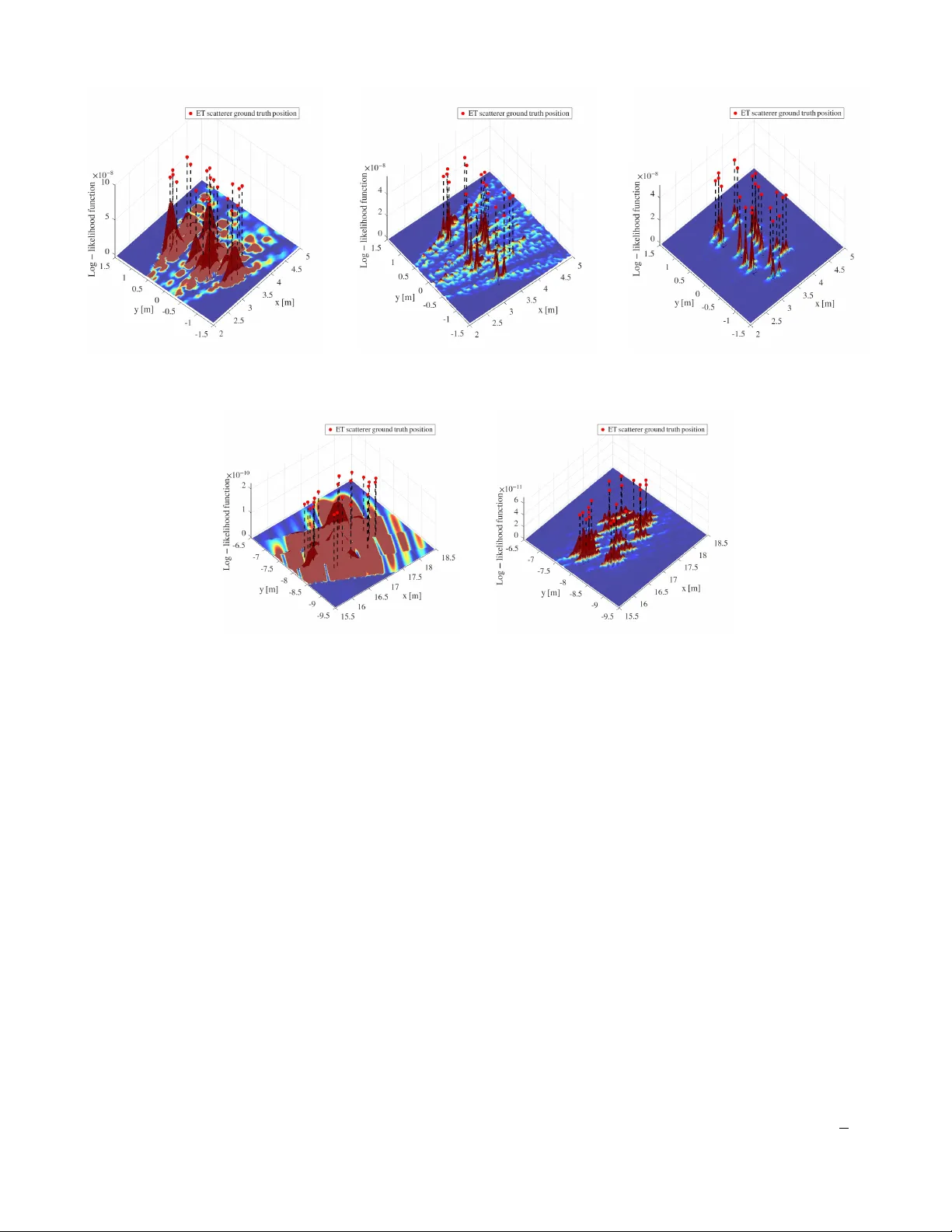
Loading comments...
Leave a Comment