Geometric analysis of Bennett's spherical 8-bar linkage and its spatial counterpart
We provide a geometric approach to two combinatorically symmmetric overconstrained spatial linkages. Both contain eight bodies and twelve revolute joints and collapse in aligned poses. The first one is spherical and the union of six spherical isogram…
Authors: Hellmuth Stachel
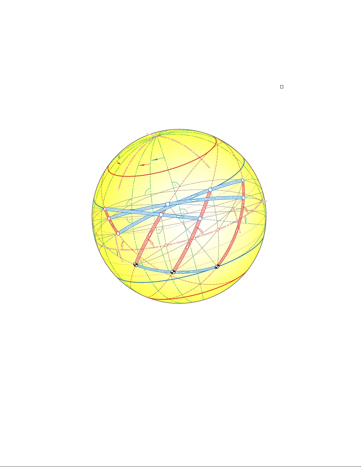
Geometric analysis of Bennett’s spherical 8-bar link age and its spatial coun terpart Hellm uth Stac hel 1 Vienna Univ ersity of T echnology , Vienna, Austria, stachel@dmg.tuwien.ac.at , WWW home page: https://www.dmg.tuwien.ac.at/stachel/ Abstract. W e pro vide a geometric approac h to t wo combinatorically symmmetric o verconstrained spatial link ages. Both con tain eight b o dies and t welv e rev olute joints and collapse in aligned poses. The first one is spherical and the union of six spherical isograms. It is the spherical image of a Bricard o ctahedron of type 3 and was already analysed 1912 b y Bennett. The second link age is the dualized version and composed from six Bennett isograms. Our approach via line reflections discloses some symmetries at spatial p oses. Keyw ords: spherical kinematics, spherical isogram, Bennett isogram, rev olute link age 1 In tro duction R. Bricard’s flexible octahedra [5] and G. T. Bennett’s isogram [4] are fascinat- ing examples of o verconstrained spatial mec hanisms with revolute joints. Both pla y an imp ortant role at the t w o types of ov erconstrained link ages whic h are presen ted b elo w. The spherical image of a Bricard o ctahedron of type 3 gives a spherical 8-bar link age that is the union of six spherical isograms (Figure 1). Bennett pro ved in [3] with the help of trigonometric relations that this link age is flexible and used this statement to confirm the flexibilit y of the type 3 o ctahedra. A particular planar coun terpart of this spherical link age is attributed to G. Darb oux [8]. E. Study’s principle of transference offers a p ossibility to transfer statements from the geometry on the sphere to spatial geometry . It is based on the dual- ization of quaternions (see, e.g., [11]) and allows to transfer Bennett’s spherical link age to a spatial link age with eigh t links and tw elv e hinges that is the union of six Bennett’s isograms (Figure 9). Also this link age is not new. E. Baker analysed in [1, Figs. 8 and 11] the spherical link age b y pro viding closure equations in terms of trigonometric func- tions. 1 In the same pap er, the planar and the spatial versions were discussed as w ell. Moreov er, Bak er presen ted other comp ounds of Bennett isograms and revisited them along with flexible 6R-lo ops in a series of publications, e.g., in [2]. 1 It is interesting that in his pap er Baker estimated Bennett’s considerations in [3] as ‘inp enetrable’ and ‘obscure’. 2 Hellm uth Stachel R 02 R 03 R 12 R 12 R 12 R 12 R 12 R 12 R 12 R 12 R 12 R 12 R 12 R 12 R 12 R 12 R 12 R 12 R 12 R 13 R 13 R 13 R 13 R 13 R 13 R 13 R 13 R 13 R 13 R 13 R 13 R 13 R 13 R 13 R 13 R 13 R 20 R 20 R 20 R 20 R 20 R 20 R 20 R 20 R 20 R 20 R 20 R 20 R 20 R 20 R 20 R 20 R 20 R 30 R 21 R 21 R 21 R 21 R 21 R 21 R 21 R 21 R 21 R 21 R 21 R 21 R 21 R 21 R 21 R 21 R 21 R 31 R 01 R 32 R 10 R 10 R 10 R 10 R 10 R 10 R 10 R 10 R 10 R 10 R 10 R 10 R 10 R 10 R 10 R 10 R 10 R 23 R 23 R 23 R 23 R 23 R 23 R 23 R 23 R 23 R 23 R 23 R 23 R 23 R 23 R 23 R 23 R 23 ϕ 1 ϕ 2 ϕ 3 g 0 h 1 h 2 h 3 h 0 g 3 g 2 g 1 g 1 g 1 g 1 g 1 g 1 g 1 g 1 g 1 g 1 g 1 g 1 g 1 g 1 g 1 g 1 g 1 F ig . 1 , k ie v f 1 c , 1 0 5 m m Fig. 1. Bennett’s composition of spherical isograms presen ted in [3, Figs. 5 and 6 ] is an o verconstrained spherical link age with 8 bars and 12 joints, arranged in six isograms. R 01 R 02 R 03 R 10 R 12 R 13 R 20 R 21 R 23 R 30 R 31 R 32 g 0 g 1 g 2 g 3 h 0 h 1 h 2 h 3 F ig . 2 , lin k g r a p h , 4 8 m m Fig. 2. At this linkgraph the links and joints of Bennet’s 6-bar link age (Figure 1) and its spatial coun terpart (Figure 9) are represented as knots and bars. The spatial version of Bennett’s 8-bar link age was also studied in a m uch more general context in [9]. Two different factorizations of a rational curv e on the Study quadric, represen ted in terms of dual quaternions, give rise to closed rev olute link ages. In particular, the factorizations of rational cubics pa ves the wa y to the spatial 6-bar link age (note the n umeric Example 3 in [9]) with the spherical v ersion as the zero-offset type. Their linkgraph, which represen ts the links and join ts of the link age as knots and bars of a graph (Figure 2), is equiv alen t to the 1-sk eleton of a cube th us rev ealing the com binatorial symmetry of this structure. Geometric analysis of Bennett’s spherical 8-bar link age 3 The goal of this article is to provide a nov el geometric approach to Bennett’s spherical 8-bar link age and its spatial counterpart. Thus, we are able to disclose some symmetries at their general poses. In our approach, reflections in lines, i.e., rotations through 180 ◦ (also called ‘halfturns’) pla y a ma jor role. Several pictures are included in order to supp ort the geometric reasoning and to illustrate the link ages. 2 The spherical 8-bar link age Let S 2 b e the unit sphere with center O . F or b etter understanding, we b egin with recalling some particularities of the geometry on the sphere S 2 . F urther details of spherical geometry can b e found, e.g., in [7, Sect. 10.1]. Since there are no straigh t lines on S 2 , their role is tak en o ver b y gr e at cir cles , i.e., circles in planes through the center O . If p oints of S 2 are lo cated on the same great circle, w e speak of aligne d p oints. – Eac h p oint P ∈ S 2 has an antip o de P ∗ , and each great circle passing through P con tains also P ∗ . Two differen t great circles g 1 , g 2 in tersects at a pair of an tip o dal p oints. – F or any tw o different p oints P and Q = P ∗ there exists a unique connecting great circle. When we sp eak of the ar c or the side P Q for any tw o non- an tip o dal p oints P , Q , we alwa ys mean on the connecting great circle the shorter of the t wo arcs terminated by P and Q . – The spheric al distanc e d P Q is defined as length of the side P Q measured on S 2 . It equals the cen tral angle < ) P O Q of the arc P Q and ob eys 0 ≤ d P Q ≤ π , when including the limiting cases Q = P and Q = P ∗ . W e consider only spherical triangles and quadrangles with sides of lengths smaller than π . – The spheric al bise ctor of any tw o different p oints P , Q ∈ S 2 is defined as the set of p oints X ∈ S 2 ob eying d X P = d X Q . Since equal spherical distances imply also equal 3D-distances along the chords, the bisector is the great circle in the plane of symmetry b et ween P and Q . – Giv en t wo great circles g 1 , g 2 , the angle < ) g 1 g 2 is defined as the angle b etw een the tangen t lines t 1 , t 2 at their intersection p oints. This angle equals the angle b et ween the planes spanned by the circles and obeys < ) g 1 g 2 = < ) t 1 t 2 ≤ π 2 . – The angle < ) QP R b etw een the arcs P Q and P R on S 2 can be b ounded b y 0 ≤ < ) QP R ≤ π . Angles of rotations ab out a p oint P ∈ S 2 can b e signed b y defining that coun ter-clo ckwise rotations (when seen from outside) are p ositiv e. Note that the sign c hanges when P is replaced b y its an tip o de P ∗ . – The p oin ts of intersection betw een differen t great circles g 1 , g 2 are the spher- ical cen ters of the unique c ommon p erp endicular great circle of g 1 and g 2 . Definition 1. A spherical quadrangle P 1 . . . P 4 is called a spheric al iso gr am if opposite sides hav e the same lengths. The quadrangle can b e free of self- in tersections or cr osse d . In the latter case tw o opposite sides are intersecting. 4 Hellm uth Stachel A B C D I 41 I 12 I 23 I 34 m a b a b α α β β γ F ig . 3 , b e n n e t t 1 n e u , 8 5 m m Fig. 3. At a skew isogram AB C D with side lengths a, b the dihedral angles α, β of its con vex hull match the prop ortion a : b = sin α : sin β . All skew isograms ha ve an axis m of symmetry . It intersects the tw o diagonals orthogonally at their midp oin ts (Figure 3, see, e.g., [10, p. 555]). The same holds for spherical isograms when the sides are replaced by c hords. Consequen tly , their axis m is the diameter of S 2 that connects the tw o in tersections S and S ∗ of the diagonal great circles. F or non-crossed isograms the axis meets the diagonal arcs at their midp oints. Otherwise, S and S ∗ are spherical centers of the great circle s that meets the diagonal arcs orthogonally at their midp oints (note Figure 4, left and righ t). Due to these symmetries, opp osite angles at spherical isograms are congruen t. If one v ertex of a spherical isogram is replaced b y its antipo de, then we obtain a quadrangle where the lengths of opp osite sides sum up to π . Lemma 1. F or any two differ ent oriente d gr e at cir cles g 1 , g 2 on S 2 ther e exists a unique p air of antip o dal c enters of symmetry S, S ∗ ∈ S 2 , i.e., spheric al c enters of a halfturn that maps g 1 to g 2 , and vic e versa. The c enters ar e lo c ate d on the c ommon p erp endicular of g 1 and g 2 . Also the r efle ction in the gr e at cir cle s with spheric al c enters S and S ∗ exchanges the oriente d gr e at cir cles g 1 and g 2 . Pr o of. The planes γ 1 , γ 2 spanned b y the great circles g 1 , g 2 in tersect each other along a line d through O . This line d must b e preserved by the wan ted halfturn. Therefore, its axis lies in the diameter plane orthogonal to d and moreo ver in one of the t wo planes that bisect the angle b etw een γ 1 and γ 2 . The images of g 1 under the tw o p ossible halfturns hav e differen t orien tation. Hence, just one of them yields the w anted orien tation of g 2 . The same holds for the reflection of g 1 in the diameter plane that is orthogonal to the axis of the correct halfturn. F rom now on w e assume that the four sides of a spherical isogram are basis, coupler and arms of a spherical coupler motion (Figure 4). It is well known that this sp ecial case of a coupler motion splits in to tw o rational one-parameter Geometric analysis of Bennett’s spherical 8-bar link age 5 R 01 R 02 R 31 R 32 S 1 ϕ 1 ϕ 2 ϕ 1 ϕ 1 ϕ 1 ϕ 1 ϕ 1 ϕ 1 ϕ 1 ϕ 1 ϕ 1 ϕ 1 ϕ 1 ϕ 1 ϕ 1 ϕ 1 ϕ 1 ϕ 1 ϕ 1 h 1 h 2 g 3 g 0 R 01 R 02 R 02 R 02 R 02 R 02 R 02 R 02 R 02 R 02 R 02 R 02 R 02 R 02 R 02 R 02 R 02 R 02 R 31 R 32 s 1 ϕ 1 ϕ 2 ϕ 1 ϕ 1 ϕ 1 ϕ 1 ϕ 1 ϕ 1 ϕ 1 ϕ 1 ϕ 1 ϕ 1 ϕ 1 ϕ 1 ϕ 1 ϕ 1 ϕ 1 ϕ 1 ϕ 1 h 1 h 2 g 3 g 3 g 3 g 3 g 3 g 3 g 3 g 3 g 3 g 3 g 3 g 3 g 3 g 3 g 3 g 3 g 3 g 0 F ig . 4 , s p h k o p p 3 a , 5 7 m m ;s p h k o p p 3 b , 5 7 m m Fig. 4. A t a non-crossed spherical isogram (left) the common midp oint S 1 of b oth diagonal arcs is a center of symmetry . A t a crossed spherical isogram (right) the axis s 1 of symmetry meets the tw o diagonal arcs orthogonally at there midp oints. If one side remains fixed, the coupler motion of a spherical isogram splits into t wo rational motions with bifurcations at the aligned p oses. motions with bifurcations in the aligned poses. During each rational motion the arms rotate in suc h a w ay that the tangents of the halved rotation angles t i := tan φ i 2 are prop ortional (see, e.g., [5] or [12, eq. (9)]). Referring to the notions used in Figure 3 holds t 2 = c 21 t 1 , where c 21 = sin( α − β ) sin α ± sin β , α = \ R 01 R 02 , β = \ R 01 R 31 . (1) Lemma 2. On a spher e S 2 , let R 01 R 02 and R 02 R 03 b e the aligne d b ases of two iso gr ams wher e the arms thr ough R 02 ar e aligne d, as wel l (Figur e 5). Then, the simultane ous c ontinuous movement of these two iso gr ams is c omp atible with a thir d iso gr am with the b asis R 01 R 03 and with arms r esp e ctively aligne d with arms of the given iso gr ams. The c enters of symmetry S 1 , S 2 and S 3 of the thr e e iso gr ams ar e aligne d. Pr o of. Let φ 1 , φ 2 and φ 3 denote the angles of rotation of the three arms relative to the initial aligned p ose on the great circle g 0 (Figure 5). By (1) the resp ective tangen ts t 1 and t 2 of halved rotation angles as w ell as t 2 and t 3 are prop ortional. Th us, the comp osition results again in an isogram motion. In order to determine the coupler of the resulting isogram, one can use the form ulas for the factors of prop ortionalit y . W e prefer a more geometric solution: Given an y non-aligned p ose, let h i b e the great circle spanned by the arm through R 0 i for i = 1 , 2 , 3. Additionally , w e transfer an arbitrarily chosen orien tation of the great circle g 0 b y the giv en rotations to an orien tation of h 1 , h 2 and h 3 . 6 Hellm uth Stachel R 01 R 02 R 03 R 12 R 13 R 21 R 23 R 31 R 32 S 1 S 2 S 3 S 3 S 3 S 3 S 3 S 3 S 3 S 3 S 3 S 3 S 3 S 3 S 3 S 3 S 3 S 3 S 3 g 0 g 1 g 2 g 3 h 1 h 2 h 3 ϕ 1 ϕ 1 ϕ 1 ϕ 1 ϕ 1 ϕ 1 ϕ 1 ϕ 1 ϕ 1 ϕ 1 ϕ 1 ϕ 1 ϕ 1 ϕ 1 ϕ 1 ϕ 1 ϕ 1 ϕ 2 ϕ 2 ϕ 2 ϕ 2 ϕ 2 ϕ 2 ϕ 2 ϕ 2 ϕ 2 ϕ 2 ϕ 2 ϕ 2 ϕ 2 ϕ 2 ϕ 2 ϕ 2 ϕ 2 ϕ 3 F ig . 5 , k ie v f 1 n , 7 0 m m Fig. 5. This triple of spherical isograms is flexible and has aligned centers of symmetry (Lemma 2). Referring to Lemma 1, we lo ok for the center S 3 of a halfturn σ 3 that sends h 1 to the opp osite orien tation h 3 of h 3 . This center S 3 is located on the great circle that meets h 1 and h 3 orthogonally . The halfturn ab out S 3 sends the basis R 01 R 03 to the w anted coupler R 23 R 21 and the great circle g 0 to the opp osite orien tation of the great circle g 2 that extends the coupler. On the other hand, there exist centers S 1 and S 2 of halfturns σ 1 and σ 2 that tak e the bases R 01 R 02 and R 02 R 03 in to the resp ectiv e couplers R 32 R 31 ⊂ g 3 and R 13 R 12 ⊂ g 1 . W e summarize: σ 1 : g 0 ↔ g 3 , h 1 ↔ h 2 , R 01 ↔ R 32 , R 02 ↔ R 31 , σ 2 : g 0 ↔ g 1 , h 2 ↔ h 3 , R 02 ↔ R 13 , R 03 ↔ R 12 , σ 3 : g 0 ↔ g 2 , h 3 ↔ h 1 , R 03 ↔ R 21 , R 01 ↔ R 23 . (2) The composition of σ 1 with σ 2 , whic h is denoted b y σ 2 σ 1 , is a rotation ρ 21 ab out the diameter p orthogonal to the axes of σ 1 and σ 2 through twice of the angle [ S 1 S 2 and sends h 1 to h 3 . The reversed pro duct σ 1 σ 2 giv es the in verse displace- men t ρ − 1 21 , i.e., the rotation ab out p through the same angle in the opp osite direction. The composition σ 3 σ 2 σ 1 of the three halfturns is an orientation preserving displacemen t, consequently a rotation that reverses the orientation of the great circle h 1 . This m ust b e a halfturn ab out a diameter of the great circle h 1 , and this is inv olutiv e. Therefore holds σ 3 σ 2 σ 1 = ( σ 3 σ 2 σ 1 ) − 1 = σ 1 σ 2 σ 3 . The equiv alent equation σ 3 ( σ 2 σ 1 ) σ 3 = σ 1 σ 2 (3) Geometric analysis of Bennett’s spherical 8-bar link age 7 rev eals that the halfturn σ 3 transforms the rotation ρ 21 in to ρ − 1 21 , which means, that it rev erses the axis p of ρ 21 . Hence, the axis of σ 3 meets p orthogonally at the sphere’s center O and is therefore coplanar with the axes of σ 1 and σ 2 . According to (2), the points R 01 and R 32 = σ 1 ( R 01 ) hav e equal distances to the plane spanned by the axes of σ 1 , σ 2 and σ 3 . And there hold similar relations for the other v ertices. R 01 R 01 R 01 R 01 R 01 R 01 R 01 R 01 R 01 R 01 R 01 R 01 R 01 R 01 R 01 R 01 R 01 R 02 R 02 R 02 R 02 R 02 R 02 R 02 R 02 R 02 R 02 R 02 R 02 R 02 R 02 R 02 R 02 R 02 R 03 R 12 R 13 R 13 R 13 R 13 R 13 R 13 R 13 R 13 R 13 R 13 R 13 R 13 R 13 R 13 R 13 R 13 R 13 R 21 R 23 R 23 R 23 R 23 R 23 R 23 R 23 R 23 R 23 R 23 R 23 R 23 R 23 R 23 R 23 R 23 R 23 R 31 R 31 R 31 R 31 R 31 R 31 R 31 R 31 R 31 R 31 R 31 R 31 R 31 R 31 R 31 R 31 R 31 R 32 R 32 R 32 R 32 R 32 R 32 R 32 R 32 R 32 R 32 R 32 R 32 R 32 R 32 R 32 R 32 R 32 R 10 R 10 R 10 R 10 R 10 R 10 R 10 R 10 R 10 R 10 R 10 R 10 R 10 R 10 R 10 R 10 R 10 R 20 R 20 R 20 R 20 R 20 R 20 R 20 R 20 R 20 R 20 R 20 R 20 R 20 R 20 R 20 R 20 R 20 R 30 R 30 R 30 R 30 R 30 R 30 R 30 R 30 R 30 R 30 R 30 R 30 R 30 R 30 R 30 R 30 R 30 N n S 1 S 2 S 3 S 3 S 3 S 3 S 3 S 3 S 3 S 3 S 3 S 3 S 3 S 3 S 3 S 3 S 3 S 3 S 3 S 4 S 5 S 6 S 6 S 6 S 6 S 6 S 6 S 6 S 6 S 6 S 6 S 6 S 6 S 6 S 6 S 6 S 6 S 6 s 1 s 2 s 3 s 4 s 5 s 6 g 0 g 0 g 0 g 0 g 0 g 0 g 0 g 0 g 0 g 0 g 0 g 0 g 0 g 0 g 0 g 0 g 0 g 1 g 2 g 2 g 2 g 2 g 2 g 2 g 2 g 2 g 2 g 2 g 2 g 2 g 2 g 2 g 2 g 2 g 2 g 3 h 0 h 1 h 2 h 2 h 2 h 2 h 2 h 2 h 2 h 2 h 2 h 2 h 2 h 2 h 2 h 2 h 2 h 2 h 2 h 3 t 1 t 2 t 1 t 2 α β F ig . 6 , k ie v f 1 o , 1 1 0 m m Fig. 6. Bennett’s spherical 8-bar link age is the union of six isograms with cen ters of symmetry S 1 , . . . , S 6 aligned on the great circle n with spherical center N (Lemma 2). The 12 join ts R ij are lo cated b y four on pairs of circles parallel and symmetric with resp ect to n . The 8 bars can b e sub divided in to tw o quadruples that make resp ectively equal angles with n . No w we are able to extend the triple of isograms depicted in Figure 5 b y additional triples to obtain Bennett’s spherical 8-bar link age sho wn in Figure 6: The great circle h 3 carries the bases R 03 R 13 and R 03 R 23 of tw o isograms with the cen ters S 2 and S 3 . By virtue of Lemma 2, there exists another spherical 8 Hellm uth Stachel isogram with the basis R 13 R 23 , with arms along g 1 and g 2 , and with the center of symmetry S 4 that m ust be aligned with S 2 and S 3 . Similarly , the bases R 01 R 31 and R 01 R 21 on h 1 b elong to the isograms with cen ters S 1 and S 3 and giv e rise to another isogram with basis R 21 R 31 , with arms along g 2 and g 3 , and with the center S 5 aligned with S 1 and S 3 . Finally , the bases R 02 R 12 and R 02 R 32 on h 2 define a sixth isogram. It has the basis R 12 R 32 , the arms along g 1 and g 3 , and the center S 6 aligned with all other cen ters S 1 , . . . , S 5 . W e summarize so far: σ 4 : g 1 ↔ g 2 , σ 5 : g 2 ↔ g 3 , σ 6 : g 3 ↔ g 1 . (4) It remains to pro ve that the couplers of the three additional isograms lie on the same great circle h 0 (note Figure 6): The great circles spanned by the first t w o additional couplers arise, respec- tiv ely , from h 3 b y the halfturn σ 4 ab out S 4 and from h 1 b y the halfturn σ 5 ab out S 5 . By (2), h 3 and h 1 are images of the opp osite orientation h 2 of h 2 under σ 2 and σ 1 , resp ectively . This implies that the couplers of the first tw o additional isograms are lo cated on the great circles σ 4 σ 2 ( h 2 ) and on σ 5 σ 1 ( h 2 ). These tw o great circles are equal since w e can state ρ 42 := σ 4 σ 2 = σ 5 σ 1 =: ρ 51 . (5) Pr o of. Both pro ducts are rotations about the axis p orthogonal to the plane of the great circle through the six centers of symmetry . Both pro ducts send g 0 to the right orientation of g 2 , the first via g 1 , the latter via g 3 . Consequently , if w e apply to g 0 the first rotation and afterwards the inv erse of the second rotation, w e obtain again g 0 with the correct orien tation. Since p cannot be the axis of the great circle g 0 , the comp osition of the tw o rotations must b e the identit y , whic h confirms the equation (5). In a similar wa y we can prov e that the sixth coupler, which is placed on σ 6 ( h 2 ), is aligned with that of the fifth isogram placed on σ 5 ( h 1 ). W e obtain it as a consequence of h 2 = σ 2 ( h 3 ), h 1 = σ 3 ( h 3 ) along with ρ 62 := σ 6 σ 2 = σ 5 σ 3 =: ρ 53 and ρ 61 := σ 6 σ 1 = σ 4 σ 3 = ρ 43 . (6) The pro ducts in (5) and (6) are rotations ab out the axis p through the p oint N ∈ S 2 , and we conclude ρ 61 : g 0 7→ g 1 , h 1 7→ h 0 , ρ 42 : g 0 7→ g 2 , h 2 7→ h 0 , ρ 53 : g 0 7→ g 3 , h 3 7→ h 0 . (7) They imply further iden tities lik e ρ 54 := σ 1 σ 2 := ρ 12 , ρ 65 := σ 2 σ 3 := ρ 23 , ρ 46 := σ 3 σ 1 := ρ 31 , (8) whic h result in congruent angles at N b etw een the symmetry axes s i of isograms as marked in Figure 6. In other words, the pairs ( s 1 , s 4 ), ( s 2 , s 5 ) and ( s 3 , s 6 ) share the spherical angle bisectors t 1 and t 2 . By virtue of (7), the distances of R 10 , R 01 , R 23 , and R 32 to the plane spanned by the centers S 1 . . . , S 6 are equal. This confirms the local symmetries that were already tak en in consideration b y Bennett in [3, Figs. 5 and 6]. Geometric analysis of Bennett’s spherical 8-bar link age 9 Theorem 1. Bennett’s spheric al six-b ar linkage as depicte d in Figur e 1 is c on- tinuously flexible with de gr e e of fr e e dom d.o.f. = 1 . In e ach p ose, the c enters of symmetry S 1 , . . . , S 6 of the c ontaine d iso gr ams ar e plac e d on a gr e at cir cle n . F or i = 1 , 2 , 3 the r otation with g 0 7→ g i ab out the spheric al c enter N of n takes h i to h 0 . The interse ctions of n with the extende d sides g 0 , . . . , g 3 and h 0 , . . . , h 3 ar e r esp e ctively symmetric w.r.t. ortho gonal gr e at cir cles t 1 , t 2 thr ough N (Figur e 6). Pr o of. As men tioned abov e, the pro duct τ 321 := σ 3 σ 2 σ 1 is a halfturn that reverses the orientation of h 1 . Therefore, the axis of τ 321 is a diameter of h 1 and, on the other hand, coplanar with the axes of σ 1 , . . . , σ 6 . Reflection in t 1 or t 2 rev eals that τ 654 := σ 6 σ 5 σ 4 is a halfturn ab out an axis symmetric to that of τ 321 , while on the other hand τ 654 c hanges the orientation of g 1 b y virtue of (4). After similar conclusions for other threefold pro ducts, this confirms the last statement. 3 The dualized version The spatial analogues of spherical isograms are Bennett isograms, i.e., flexible 4R c hains where the common perp endiculars of neigh b oring hinges form a closed sk ew isogram (Figure 7). In eac h spatial pose, there exists a line s such that the reflection in s exchanges opposite v ertices, hinges and angles (Figure 3). According to [6], the Bennett isogram is the only 4R loop which is contin uously flexible. I 01 I 02 I 32 I 31 R 01 R 01 R 01 R 01 R 01 R 01 R 01 R 01 R 01 R 01 R 01 R 01 R 01 R 01 R 01 R 01 R 01 R 02 R 02 R 02 R 02 R 02 R 02 R 02 R 02 R 02 R 02 R 02 R 02 R 02 R 02 R 02 R 02 R 02 R 32 R 31 ϕ 2 ϕ 1 ϕ 1 g 0 g 3 h 2 h 1 s F ig . 7 , b e n n e t t 2 n e u , 9 0 m m Fig. 7. The Bennett isogram is a flexible 4R loop where the common perp endiculars b e- t ween adjacent hinges form an isogram. The reflection in the line s exc hanges opp osite sides, angles and hinges. The hinges of a Bennett isogram define as their spherical image a spherical isogram. This reveals that the angles of rotation for neighbouring sides ob ey again the equation (1). Hence, similar to Lemma 2 the comp osition of tw o Ben- nett isograms with aligned bases R 01 R 02 and R 01 R 02 on g 0 and aligned arms 10 Hellm uth Stachel R 02 R 32 and R 02 R 32 on h 2 , as shown in Figure 8, yield a transmission according to (1) from the first arm R 01 R 31 on h 1 of the first isogram to the last arm R 01 R 13 on h 3 of the second. This shows that a third Bennett isogram with basis R 01 R 03 is compatible with the motions of the first t wo isograms. When w e assign orientations to the sides g 0 , h 1 , h 2 , h 3 lik e previously , then the reflection in the axis of symmetry s 3 of the third isogram is defined by sending h 1 to the rev ersed orientation h 3 of h 3 . Therefore, it passes through the midp oin t of the shortest segmen t b etw een h 1 and h 3 and has the direction of an angle bisector b etw een the directions of h 1 and h 3 . R 01 R 01 R 01 R 01 R 01 R 01 R 01 R 01 R 01 R 01 R 01 R 01 R 01 R 01 R 01 R 01 R 01 R 02 R 02 R 02 R 02 R 02 R 02 R 02 R 02 R 02 R 02 R 02 R 02 R 02 R 02 R 02 R 02 R 02 R 03 R 03 R 03 R 03 R 03 R 03 R 03 R 03 R 03 R 03 R 03 R 03 R 03 R 03 R 03 R 03 R 03 R 12 R 12 R 12 R 12 R 12 R 12 R 12 R 12 R 12 R 12 R 12 R 12 R 12 R 12 R 12 R 12 R 12 R 13 R 13 R 13 R 13 R 13 R 13 R 13 R 13 R 13 R 13 R 13 R 13 R 13 R 13 R 13 R 13 R 13 R 21 R 21 R 21 R 21 R 21 R 21 R 21 R 21 R 21 R 21 R 21 R 21 R 21 R 21 R 21 R 21 R 21 R 23 R 23 R 23 R 23 R 23 R 23 R 23 R 23 R 23 R 23 R 23 R 23 R 23 R 23 R 23 R 23 R 23 R 31 R 31 R 31 R 31 R 31 R 31 R 31 R 31 R 31 R 31 R 31 R 31 R 31 R 31 R 31 R 31 R 31 R 32 R 32 R 32 R 32 R 32 R 32 R 32 R 32 R 32 R 32 R 32 R 32 R 32 R 32 R 32 R 32 R 32 ϕ 1 ϕ 1 ϕ 1 ϕ 1 ϕ 1 ϕ 1 ϕ 1 ϕ 1 ϕ 1 ϕ 1 ϕ 1 ϕ 1 ϕ 1 ϕ 1 ϕ 1 ϕ 1 ϕ 1 ϕ 2 ϕ 2 ϕ 2 ϕ 2 ϕ 2 ϕ 2 ϕ 2 ϕ 2 ϕ 2 ϕ 2 ϕ 2 ϕ 2 ϕ 2 ϕ 2 ϕ 2 ϕ 2 ϕ 2 ϕ 3 g 0 g 0 g 0 g 0 g 0 g 0 g 0 g 0 g 0 g 0 g 0 g 0 g 0 g 0 g 0 g 0 g 0 g 1 g 1 g 1 g 1 g 1 g 1 g 1 g 1 g 1 g 1 g 1 g 1 g 1 g 1 g 1 g 1 g 1 g 2 g 2 g 2 g 2 g 2 g 2 g 2 g 2 g 2 g 2 g 2 g 2 g 2 g 2 g 2 g 2 g 2 g 3 g 3 g 3 g 3 g 3 g 3 g 3 g 3 g 3 g 3 g 3 g 3 g 3 g 3 g 3 g 3 g 3 h 1 h 1 h 1 h 1 h 1 h 1 h 1 h 1 h 1 h 1 h 1 h 1 h 1 h 1 h 1 h 1 h 1 h 2 h 2 h 2 h 2 h 2 h 2 h 2 h 2 h 2 h 2 h 2 h 2 h 2 h 2 h 2 h 2 h 2 h 3 h 3 h 3 h 3 h 3 h 3 h 3 h 3 h 3 h 3 h 3 h 3 h 3 h 3 h 3 h 3 h 3 F ig . 8 , k ie v f 1 p a , 9 0 m m Fig. 8. A flexible triple of Bennett isograms with aligned bases on g 0 , arms on the lines h 1 , h 2 and h 3 , and couplers on the lines g 3 , g 1 and g 2 . W e adopt the notation from the spherical case and denote the line reflections of the three isograms with σ 1 , σ 2 and σ 3 . Th us, w e can follow the lines of the foregoing section nearly word for word. The only difference is that no w the comp osition σ 2 σ 1 of the first t wo reflections is a helical displacemen t ab out the common perp endicular n of the t w o resp ectiv e axes s 1 and s 2 , that tak es h 1 with R 31 and the hinge I 31 to h 3 with R 13 and I 13 . Since the pro duct τ 321 := σ 3 σ 2 σ 1 is a helical displacement that keeps the line h 1 fixed but reverses its orien tation, τ 321 m ust b e the reflection in a line orthogonal to h 1 . This implies by (3) lik e ab o ve, that s 3 in tersects n p erp endicularily , to o. Moreov er, the axis of τ 321 is the common p erp endicular of h 1 and n . After extending the first triple of Bennett isograms b y three additional iso- grams, w e obtain additional line reflections σ 4 , σ 5 and σ 6 that satisfy the equa- tions (5)—(8). This confirms that the additional isograms hav e aligned couplers Geometric analysis of Bennett’s spherical 8-bar link age 11 R 01 R 01 R 01 R 01 R 01 R 01 R 01 R 01 R 01 R 01 R 01 R 01 R 01 R 01 R 01 R 01 R 01 R 02 R 02 R 02 R 02 R 02 R 02 R 02 R 02 R 02 R 02 R 02 R 02 R 02 R 02 R 02 R 02 R 02 R 03 R 03 R 03 R 03 R 03 R 03 R 03 R 03 R 03 R 03 R 03 R 03 R 03 R 03 R 03 R 03 R 03 R 10 R 10 R 10 R 10 R 10 R 10 R 10 R 10 R 10 R 10 R 10 R 10 R 10 R 10 R 10 R 10 R 10 R 12 R 12 R 12 R 12 R 12 R 12 R 12 R 12 R 12 R 12 R 12 R 12 R 12 R 12 R 12 R 12 R 12 R 13 R 13 R 13 R 13 R 13 R 13 R 13 R 13 R 13 R 13 R 13 R 13 R 13 R 13 R 13 R 13 R 13 R 20 R 20 R 20 R 20 R 20 R 20 R 20 R 20 R 20 R 20 R 20 R 20 R 20 R 20 R 20 R 20 R 20 R 21 R 21 R 21 R 21 R 21 R 21 R 21 R 21 R 21 R 21 R 21 R 21 R 21 R 21 R 21 R 21 R 21 R 23 R 23 R 23 R 23 R 23 R 23 R 23 R 23 R 23 R 23 R 23 R 23 R 23 R 23 R 23 R 23 R 23 R 30 R 30 R 30 R 30 R 30 R 30 R 30 R 30 R 30 R 30 R 30 R 30 R 30 R 30 R 30 R 30 R 30 R 31 R 31 R 31 R 31 R 31 R 31 R 31 R 31 R 31 R 31 R 31 R 31 R 31 R 31 R 31 R 31 R 31 R 32 R 32 R 32 R 32 R 32 R 32 R 32 R 32 R 32 R 32 R 32 R 32 R 32 R 32 R 32 R 32 R 32 S 1 S 2 S 2 S 2 S 2 S 2 S 2 S 2 S 2 S 2 S 2 S 2 S 2 S 2 S 2 S 2 S 2 S 2 S 3 S 3 S 3 S 3 S 3 S 3 S 3 S 3 S 3 S 3 S 3 S 3 S 3 S 3 S 3 S 3 S 3 S 6 S 6 S 6 S 6 S 6 S 6 S 6 S 6 S 6 S 6 S 6 S 6 S 6 S 6 S 6 S 6 S 6 s 1 s 1 s 1 s 1 s 1 s 1 s 1 s 1 s 1 s 1 s 1 s 1 s 1 s 1 s 1 s 1 s 1 s 2 s 2 s 2 s 2 s 2 s 2 s 2 s 2 s 2 s 2 s 2 s 2 s 2 s 2 s 2 s 2 s 2 s 3 s 3 s 3 s 3 s 3 s 3 s 3 s 3 s 3 s 3 s 3 s 3 s 3 s 3 s 3 s 3 s 3 s 4 s 5 s 6 s 6 s 6 s 6 s 6 s 6 s 6 s 6 s 6 s 6 s 6 s 6 s 6 s 6 s 6 s 6 s 6 I 01 I 01 I 01 I 01 I 01 I 01 I 01 I 01 I 01 I 01 I 01 I 01 I 01 I 01 I 01 I 01 I 01 I 02 I 03 I 03 I 03 I 03 I 03 I 03 I 03 I 03 I 03 I 03 I 03 I 03 I 03 I 03 I 03 I 03 I 03 I 12 I 12 I 12 I 12 I 12 I 12 I 12 I 12 I 12 I 12 I 12 I 12 I 12 I 12 I 12 I 12 I 12 I 13 I 13 I 13 I 13 I 13 I 13 I 13 I 13 I 13 I 13 I 13 I 13 I 13 I 13 I 13 I 13 I 13 I 21 I 23 I 31 I 31 I 31 I 31 I 31 I 31 I 31 I 31 I 31 I 31 I 31 I 31 I 31 I 31 I 31 I 31 I 31 I 32 I 10 I 10 I 10 I 10 I 10 I 10 I 10 I 10 I 10 I 10 I 10 I 10 I 10 I 10 I 10 I 10 I 10 I 20 I 30 I 30 I 30 I 30 I 30 I 30 I 30 I 30 I 30 I 30 I 30 I 30 I 30 I 30 I 30 I 30 I 30 n g 0 g 0 g 0 g 0 g 0 g 0 g 0 g 0 g 0 g 0 g 0 g 0 g 0 g 0 g 0 g 0 g 0 g 1 g 1 g 1 g 1 g 1 g 1 g 1 g 1 g 1 g 1 g 1 g 1 g 1 g 1 g 1 g 1 g 1 g 2 g 2 g 2 g 2 g 2 g 2 g 2 g 2 g 2 g 2 g 2 g 2 g 2 g 2 g 2 g 2 g 2 g 3 g 3 g 3 g 3 g 3 g 3 g 3 g 3 g 3 g 3 g 3 g 3 g 3 g 3 g 3 g 3 g 3 h 0 h 0 h 0 h 0 h 0 h 0 h 0 h 0 h 0 h 0 h 0 h 0 h 0 h 0 h 0 h 0 h 0 h 1 h 1 h 1 h 1 h 1 h 1 h 1 h 1 h 1 h 1 h 1 h 1 h 1 h 1 h 1 h 1 h 1 h 2 h 2 h 2 h 2 h 2 h 2 h 2 h 2 h 2 h 2 h 2 h 2 h 2 h 2 h 2 h 2 h 2 h 3 h 3 h 3 h 3 h 3 h 3 h 3 h 3 h 3 h 3 h 3 h 3 h 3 h 3 h 3 h 3 h 3 F ig . 9 , k ie v f 1 p b , 1 0 5 m m Fig. 9. The spatial version of Bennett’s spherical 8-bar link age consists of 8 bo dies Γ 0 , . . . , ∆ 3 and 12 hinges I 01 . . . I 32 , arranged in 6 Bennett isograms. In each spatial p ose, the axes of symmetry s 1 , . . . , s 6 of the six isograms hav e the line n as their common p erp endicular. on the line h 0 while the axes of symmetry s 1 . . . s 3 of all six isograms are placed suc h that the pairs ( s 1 , s 4 ), ( s 2 , s 5 ) and ( s 3 , s 6 ) ha v e a common axis of symmetry t orthogonal to n (Figure 10). As a consequence, the lines g 0 , . . . , g 3 ha ve equal distances to n and mak e congruen t angles with n , and the same holds for the distances and angles betw een the lines h 0 , . . . , h 3 and n . S 1 t t s 1 s 2 s 3 s 4 s 5 s 6 S 1 S 2 S 3 S 4 S 5 S 6 n F ig . 1 0 , k ie v f 1 q , 1 0 5 m m Fig. 10. The axes of symmetry s 1 , . . . , s 6 meet the line n orthogonally . They are placed in such a wa y that the pairs ( s 1 , s 4 ), ( s 2 , s 5 ) and ( s 3 , s 6 ) hav e a common axis t of symmetry . Left: View orthogonal to n . Right: Poin t view of n . 12 Hellm uth Stachel Theorem 2. The sp atial version of Bennett’s spheric al eight-b ar linkage is a c omp ound of six Bennett iso gr ams (Figur e 9) and c ontinuously flexible with d.o.f. = 1 . In e ach p ose, the axes of symmetry s 1 , . . . , s 6 of the c ontaine d iso- gr ams have a c ommon p erp endicular n . F or i = 1 , 2 , 3 holds that the helic al displac ement ab out n with g 0 7→ g i takes si- multane ously h i to h 0 . The c ommon p erp endiculars b etwe en n and g 0 , . . . , g 3 ar e r esp e ctively symmetric to the c ommon p erp endiculars b etwe en n and h 0 , . . . , h 3 with r esp e ct to an axis t (Figur e 10). Notes and Comments The author expresses sincere thanks to Hans-P eter Sc hr¨ oc ker, Univ ersity of Inns- bruc k, for useful advice. References 1. J.E. Baker: On Bric ar d’s doubly c ol lapsible o ctahe dr on and its planar, spherical and skew counterp arts. J. F ranklin Inst. 332B /(6), 657–679 (1995). 2. J.E. Bak er: A c ol lapsible network of similar p airs of neste d Bennett linkages. Mech. Mac h. Theory 59 , 119–124 (2013). 3. G.T. Bennett: Deformable o ctahe dr a. Proc. London Math. So c., 2 nd series, 10 , 309– 343 (1912). 4. G.T. Bennett: The skew iso gr am me chanism. Pro c. London Math. So c., 2 nd series, 13 , 151–173. (1914). 5. R. Bricard: M´ emoir e sur la th´ eorie de l’o cta ` edr e articul´ e. J. math. pures appl., Liouville, S ´ er. 5, 3 , 113–148 (1897). 6. K. Brunnthaler, H.-P . Schr¨ oc ker, M. Husty: A New Metho d for the Synthesis of Bennett Mechanisms. Pro ceedings of CK 2005, International W orkshop on Compu- tational Kinematics, Cassino 2005. 7. G. Glaeser, H. Stachel, B. Odehnal: The Universe of Conics. F rom the ancien t Greeks to 21 st cen tury dev elopments. 2 nd ed., Springer Spectrum, Berlin, Heidelb erg 2024. 8. G. Darb oux: R e cher ches sur un syst` eme articul ´ e. Bull. Sci. Math. Astronom., 2 e s ´ erie, 3 /1, 151–192 (1879). 9. G. Heged ¨ us, J. Sc hicho, H.-P . Schr¨ ock er: F actorization of rational curves in the Study quadric. Mech. Mach. Theory 69 , 142–152 (2013). 10. B. Odehnal, H. Stac hel, G. Glaeser: The Universe of Quadrics. Springer Sp ectrum, Berlin, Heidelb erg, 2020. 11. H. Stac hel: Euclide an line ge ometry and kinematics in the 3-sp ac e. In N.K. Art ´ emiadis, N.K. Stephanidis (eds.): Pro c. 4th Internat. Congress of Geometry , Thessaloniki 1996, A thens: Aristotle Universit y of Thessaloniki 1997, pp. 380–391. 12. H. Stac hel: A kinematic appro ach to Kokotsakis meshes. Comput. Aided Geom. Des. 27 , 428–437 (2010).
Original Paper
Loading high-quality paper...
Comments & Academic Discussion
Loading comments...
Leave a Comment