Low-Thrust Trajectory Optimization for Cubesat Lunar Mission: HORYU-VI
This paper presents a low-thrust trajectory optimization strategy to achieve a near-circular lunar orbit for a CubeSat injected into a lunar flyby trajectory. The 12U CubeSat HORYU-VI is equipped with four Hall-effect thrusters and designed as a seco…
Authors: Omer Burak Iskender, Keck Voon Ling, Mengu Cho
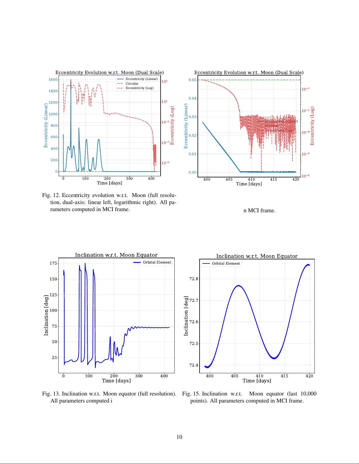
1. Introduction IA C–20–C1,4,8,x55549 L OW- T H R U S T T R A J E C T O RY O P T I M I Z A T I O N F O R C U B E S A T L U N A R M I S S I O N : H O R Y U - V I Omer Burak Iskender a,* , Keck V oon Ling c , Mengu Cho b,c , Sangkyun Kim b , and Necmi Cihan Orger b a Nanyang T echnological Univer sity , Singapor e, iske0001@e .ntu.edu.sg b K yushu Institute of T echnology , Kitakyushu, J apan c Nanyang T echnological Univer sity , Singapor e * Corr esponding author Abstract This paper presents a low-thrust trajectory optimization strate gy to achiev e a near-circular lunar orbit for a CubeSat injected into a lunar flyby trajectory . The 12U CubeSat HOR YU-VI is equipped with four hall-ef fect thrusters and designed as a secondary payload on NASA ’ s Space Launch System under the Artemis program. Upon release, the spacecraft gains suf ficient energy to escape the Earth–Moon system after a lunar flyby . The proposed trajectory is decomposed into three phases: (1) pre-flyby deceleration to a void heliocentric escape, (2) lunar gra vitational capture, and (3) orbit circularization to the science orbit. For each phase, an impulsi ve-b urn solution is first computed as an initial guess, which is then refined through finite-burn optimization using Sequential Quadratic Programming (SQP). The dynamical model incorporates Earth–Moon–Sun–Jupiter gra vitational interactions and a high-fidelity lunar gravity field. All trajectories are independently verified with NASA ’ s General Mission Analysis T ool (GMA T). Results demonstrate that HOR YU-VI achiev es lunar capture within 200 days, establishes a stable science orbit at 280 days, and can spiral down to a near-circular 100 km orbit by 450 days, using a total ∆ V of 710 m/s, well within the capability of the electric propulsion system. Keyw ords: Electric Propulsion, Trajectory Optimization, Lo w Thrust, CubeSat, Lunar Mission, HOR YU-VI Published at the 71st International Astr onautical Congr ess (IA C 2020), The CyberSpace Edition, 12–14 October 2020. P aper ID: IAC–20–C1,4,8,x55549. 1. I N T R O D U C T I O N CubeSat platforms hav e rapidly expanded their reach from Low Earth Orbit (LEO) to cislunar and interplane- tary space, offering cost-effecti ve spacecraft for scientific and technological objectiv es. 2, 6, 10, 14, 24 Lunar science has emerged as a primary focus for next-generation CubeSat missions. The HOR YU-VI mission is an international Cube- Sat initiati ve to in v estigate the lunar dust en vironment through multi-epoch imaging of the Lunar Horizon Glow (LHG). 22 The project is a collaboration among Kyushu Institute of T echnology (Japan), Nan yang T echnologi- cal Uni versity (Singapore), Sapienza University of Rome (Italy), California Polytechnic State University (USA), Univ ersity of Colorado Boulder (USA), and Aliena Pte. Ltd. (Singapore). The 12U CubeSat platform carries ded- icated imaging instruments for LHG observations from a low-altitude lunar orbit. The LHG (an anomalous brightness above the lu- nar terminator exceeding the Coronal Zodiacal Light (CZL) baseline) was first observ ed during the Apollo era. 4, 17, 18, 26 Lunar dust poses hazards to both cre wed mis- sions (respiratory risks, contamination, long-term health effects) 7, 11, 13, 15 and robotic systems (optical degradation, thermal property alterations, electrical discharges). 8, 20, 21 Characterizing the near-surf ace dust population from or- bit remains an open challenge in lunar science. 1, 3, 5, 9, 27 Low-thrust propulsion (where each thruster head pro- duces sub-millinewton thrust levels, resulting in milli- g or lo wer acceleration) is fundamentally dif ferent from the high-thrust impulsiv e maneuvers used in conv entional di- rect lunar transfers. For CubeSats, low thrust typically means less than 1 mN per thruster , with burn durations on the order of months. The enabling technology is elec- tric propulsion (EP), which uses electrical po wer to ac- celerate a propellant and thereby impart velocity changes with high fuel efficienc y . EP of fers three principal advan- tages over chemical systems: high specific impulse (and hence lo w propellant consumption), low hardware cost, and highly controllable, precise thrust vectoring. The technology traces back to the first space-qualified ion en- gines in 1964, followed by pulsed plasma thrusters, and 1 2. T rajectory Options T able 1. Lunar transfer methods with typical duration and representativ e missions. 23 T ransfer T ype T ypical Duration Benefits Example Direct, con ventional 3–6 days W ell known, quick Apollo, LR O Direct, staging 2–10 weeks Quick, many launch days Clementine, CH-1 Direct to lunar L1 1–5 weeks Staging at L1 Fe w to date Lo w-thrust Many months Lo w fuel, many launch days SMAR T -1 Lo w-energy 2.5–4 months Lo w fuel, many launch days Hiten, GRAIL, AR TEMIS LR O: Lunar Reconnaissance Orbiter; CH-1: Chandrayaan-1; SMAR T -1: Small Missions for Advanced Research in T echnology . the Hall-ef fect thrusters that are now the most common EP devices for small satellites. This paper addresses the trajectory design challenge for HOR YU-VI. The launch opportunity was en visioned as a secondary payload on NASA ’ s Space Launch Sys- tem (SLS) under the Artemis program. Upon separation, the CubeSat enters a high-eccentricity orbit ( e = 0 . 9667 ) with sufficient energy for lunar flyby and subsequent he- liocentric escape if left uncontrolled. Con verting this tra- jectory into a stable lunar orbit requires precise multi- phase low-thrust maneuvers within the se vere propulsion constraints of a CubeSat platform. 2. T R A J E C T O RY O P T I O N S T able 1 summarizes established lunar transfer meth- ods. 23 The SMAR T -1 mission pioneered lo w-thrust cislunar transfers using a Hall-effect thruster, requir- ing ∼ 14 months to reach lunar orbit from GT O. 25 Its four-phase approach (GT O spiral-out, further orbit rais- ing, lunar capture via Pontryagin’ s Maximum Principle, and circularization) provides the operational heritage for HOR YU-VI. The present work adopts a similar phased decomposition b ut dif fers in that the initial orbit is a high- energy flyby trajectory rather than GT O. 3. M I S S I O N A R C H I T E C T U R E The HOR YU-VI spacecraft is a 12U CubeSat (dry mass 9 kg, propellant 3 kg, wet mass 12 kg) equipped with four hall-effect thrusters ( I sp = 1000 s) providing a combined nominal thrust of 1.2 mN (1.08 mN ef fectiv e, assuming 10% inefficienc y), and a total ∆ V capability of 930 m/s. T able 2 presents the spacecraft state at separation from the launch vehicle. Fig. 1 shows the CAD model. 3.1 Uncontr olled trajectory Ballistic propagation of the initial state rev eals that the spacecraft performs an uncontrolled lunar flyby at approx- imately 1300 km altitude and subsequently escapes into a heliocentric orbit after ∼ 4.2 days (Figs. 2–3). T o establish a stable lunar orbit, the mission trajectory is divided into four segments: Fig. 1. CAD design of HOR YU-VI CubeSat. T able 2. Spacecraft state at separation from the launch ve- hicle. 16, 19 Parameter V alue Unit Parameter V alue Unit X − 15015.4 km SMA 205954.8 km Y − 23569 km Ecc 0.9667 Z 2241.505 km Inc 28.6065 deg VX − 0.48554 km/s RAAN 65.9569 deg VY − 5.04876 km/s AoP 47.9162 deg VZ − 0.87999 km/s T A 122.4711 deg Epoch 15 December 2017 Se gment 0 – Detumbling and commissioning ( ∼ 2 hours): Immediately after separation, the space- craft detumbles and establishes the communication network. This preliminary segment must complete before propulsiv e maneuvers can be gin. Phase 1 – Pr e-flyby deceler ation: Anti-velocity (retro- grade) thrust is applied ov er approximately 2 days to re- duce the spacecraft energy below the lunar escape thresh- old. Phase 2 – Lunar capture: The spacecraft is tran- sitioned from Earth–Moon transfer to a highly eccen- tric ( e ≈ 0 . 7 ) lunar orbit with a semi-major axis a ≤ 32 , 000 km through optimized thrust sequences over mul- tiple perilune passages. Phase 3 – Orbit circularization: Retrograde finite burns o ver 400 successi ve perilune passages reduce ec- centricity from e ≈ 0 . 7 to near-circular ov er ∼ 270 days, 2 3.2 Reference frames achieving the 100 km science orbit. (a) Earth-centered frame (b) Moon-centered frame Fig. 2. T rajectory without actuation. 0 2 4 6 8 10 10 3 10 4 10 5 10 6 4 4.5 5 1000 2000 3000 4000 Fig. 3. Lunar altitude history without actuation. 3.2 Refer ence frames The trajectory analysis employs three coordinate frames: Earth-Center ed Inertial (ECI): The primary frame for trajectory propagation. The origin is at the Earth’ s cen- ter of mass, with the X -axis directed toward the vernal equinox at the J2000 epoch and the Z -axis tow ard the ce- lestial north pole. The axes are non-rotating (inertially fixed). The equations of motion (Eq. (1)) and the GMA T verification are formulated in this frame. Earth-Center ed Earth-F ixed (ECEF): The origin co- incides with ECI b ut the axes rotate with the Earth at sidereal rate. The X -axis passes through the Greenwich meridian. This frame is used for ground-station visibility calculations and launch geometry , but is not used for orbit propagation. Moon-Center ed Inertial (MCI): The origin is at the Moon’ s center of mass, with ax es parallel to the ECI J2000 frame. Lunar orbital elements, altitude his- tories, and the capture/circularization trajectory plots (Figs. 2b, 7) are presented in this frame. Lunar altitude is computed in a selenocentric body-fixed frame that ro- tates with the Moon. 3.3 Dynamical model The equations of motion are formulated in the ECI frame incorporating n-body gravitational dynamics: ¨ r = − µ ⊕ r 3 r − µ M r − r M | r − r M | 3 + r M r 3 M + a 3rd + F thrust m (1) where µ ⊕ and µ M are the gravitational parameters of Earth and Moon, r M ( t ) is the lunar position from JPL ephemerides, and a 3rd accounts for Sun and Jupiter per- turbations. Near the Moon, the GGLP1500D gra vity field (degree and order 1500) replaces the point-mass lunar model. The combined thrust from all activ e thrusters is bounded by: ∥ F total ∥ ≤ 1 . 2 mN (2) with a 10% inef ficiency mar gin applied in the GMA T simulation (thrust scale factor 0.9), yielding an ef fectiv e thrust of 1.08 mN. The exhaust velocity is v e = g 0 I sp ≈ 9 . 81 km/s. 4. T R A J E C T O RY O P T I M I Z AT I O N 4.1 Pr oblem formulation A con ventional approach to trajectory design is to solve a targeting problem using differential corrections, which satisfies endpoint constraints but does not optimize the trajectory . Instead, this work optimizes the low-thrust tra- jectory with a time-varying thrust profile using nonlinear programming. While commercial solvers such as SNOPT and IPOPT are av ailable, the optimization requires high- fidelity force models to accurately capture flight dynam- ics ov er multi-month transfer durations. N ASA ’ s Gen- eral Mission Analysis T ool (GMA T) 12 provides out-of- the-box force models and numerical propagators at the highest av ailable fidelity , and its b uilt-in YUKON op- timizer (a nonlinear programming solver based on Se- quential Quadratic Programming (SQP)) w as therefore adopted. T o achieve the best orbit propagation accu- racy , two separate thruster models are employed: an Earth-centered thruster whose thrust direction is defined in the Earth VNB (velocity–normal–binormal) frame for Phases 1–2 (when the spacecraft is in Earth’ s close prox- imity), and a Moon-centered thruster whose direction is defined in the lunar VNB frame for capture and circu- larization (during lunar close proximity). This hybrid formulation ensures that the central body providing the dominant gra vitational field is used for propagation in 3 4.1 Problem formulation each phase, a voiding numerical errors from computing small perturbation differences relativ e to a distant pri- mary . The design variables for the YUKON optimization are the three-dimensional thrust direction vectors for the transition-burn and capture-burn phases ( ˆ d ⊕ , ˆ d M ∈ R 3 ), the transition-burn duration ∆ t burn , and the coast dura- tion between transition and capture ∆ t coast , yielding eight design variables in total. The constrained optimization problem is formulated as: find ˆ d ⊕ , ˆ d M , ∆ t burn , ∆ t coast feasible trajectory subject to ˙ r = v , ˙ v = a grav + F thrust m 0 ≤ ∥ F thrust ∥ ≤ F max r perilune ≥ 6 , 000 km C 3 ≤ − 0 . 11 km 2 / s 2 (3) where r perilune is the periapsis distance from the Moon’ s center and C 3 is the characteristic energy with respect to the Moon at the end of the capture b urn. The periapsis constraint ensures suf ficient altitude to av oid surface im- pact, while the C 3 constraint guarantees gravitational cap- ture (negati ve C 3 indicates an elliptical, bound orbit). The dynamical constraints follo w Eq. (1) and the thrust bound from Eq. (2). The choice of capture constraints was determined through a systematic trade study (T able 3), motiv ated by three distinct failure modes observed in our simulations: 1. No feasible solution: When low eccentricity con- straints are enforced ( e ≤ 0 . 4 ), the optimizer cannot find a trajectory satisfying all constraints simultane- ously . 2. Escape: The optimizer con ver ges and constraints are satisfied, but the post-capture orbit is not stable (the CubeSat escapes from the Moon’ s gravitational at- traction). 3. Surface impact: Constraints are satisfied and the Moon is the dominant gravitational attractor; how- ev er , the CubeSat crashes onto the lunar surface due to insufficient periapsis altitude. Three constraint formulations were ev aluated to ad- dress these failure modes: (i) eccentricity alone, (ii) ec- centricity with a semi-major axis upper bound, and (iii) C 3 energy with a perilune distance (RMA G) lo wer bound. Constraining only eccentricity , the optimizer con- ver ges for all tested values; howe ver , for e ≤ 0 . 6 the or- bit remains hyperbolic and the spacecraft escapes (fail- ure mode 2), while e = 0 . 7 achie ves capture but results in a periapsis belo w the lunar surf ace (failure mode 3). Adding an SMA constraint prev ents escape at all eccen- tricities, yet the periapsis altitude remains unsafely low . Only the C 3 –RMA G formulation ( C 3 ≤ − 0 . 11 km 2 /s 2 , r perilune ≥ 6000 km) simultaneously guarantees gravita- tional capture and a safe periapsis altitude. The final im- plementation adopts the C 3 –RMA G formulation for the YUK ON optimizer, providing robust capture with ade- quate margin abo ve the lunar surface. 4.1.1 Lunar captur e (Phase 2) The optimized capture sequence proceeds as follows: af- ter the pre-flyby deceleration burn (Phase 1), the space- craft coasts for approximately 77.5 days through multi- ple lunar passages. The YUKON optimizer then deter- mines (i) the Earth-VNB thrust direction and duration ( ∼ 10 days) for the transition burn, (ii) a coast interval ( ∼ 33 days), and (iii) the Moon-VNB thrust direction for a capture burn that terminates at the next lunar periapsis. The capture burn switches the thruster reference frame from Earth-centered to Moon-centered VNB, aligning the thrust vector with the local v elocity direction relative to the Moon for maximum deceleration efficiency . At the end of this sequence, the spacecraft achiev es lunar cap- ture with C 3 ≤ − 0 . 11 km 2 /s 2 and periapsis altitude abov e 6000 km. 4.1.2 Orbit cir cularization (Phase 3) Follo wing capture, the orbit is circularized through a de- terministic sequence of 400 retrograde finite-burn arcs distributed over successi ve perilune passages. The Moon- centered thruster is set to a fix ed retrograde direction ( ˆ d M = [ − 1 , 0 , 0] T in lunar VNB). Each cycle consists of a thrust arc spanning true anomaly ν = 240 ◦ → 130 ◦ (passing through periapsis at ν = 0 ◦ ), follo wed by a coast arc from ν = 130 ◦ → 240 ◦ (passing through apoap- sis at ν = 180 ◦ ). By thrusting retrograde near periap- sis, the apoapsis altitude is progressiv ely lowered each orbit, reducing eccentricity to ward near-circular . This burn–coast architecture concentrates the ∆ V where grav- itational losses are lowest and a voids continuous thrusting through the apoapsis region where retrograde thrust would inefficiently raise the periapsis. A distinguishing feature of this problem is that the de- sign variables extend beyond the conv entional thrust di- rection vector . In most lo w-thrust trajectory optimization studies, the control is the thrust orientation profile and the transfer duration is either fixed or a single scalar parame- ter . Here, the CubeSat’ s limited thrust capability (1.2 mN) is insufficient to achiev e lunar gravitational capture during a single flyby passage (ev en under continuous maximum retrograde thrust, the hyperbolic excess velocity cannot be reduced below the escape threshold within the brief perilune window). The spacecraft must therefore execute 4 4.2 Impulsiv e-burn approximation T able 3. Constraint trade study for Phase 2 lunar capture. Three formulations are compared: eccentricity only , eccen- tricity with SMA bound, and C 3 energy with perilune distance (RMA G). Ecc constraint Ecc + SMA constraint C 3 + RMA G V alue 0.5 0.6 0.7 0.5 0.6 0.7 − 0 . 15 km 2 /s 2 , 6000 km Constraint satisfaction Y es Y es Y es Y es Y es Y es Y es A void escape No No Y es Y es Y es Y es Y es A void lunar crash – – No No No No Y es Fig. 4. Impulsiv e-burn trajectories in the Moon-centered frame. multiple lunar passages, and the thrust-arc durations and coast interv als between successiv e encounters become es- sential decision variables alongside the thrust direction. This couples the inherently discrete question of how many passages are requir ed with the continuous optimization of when to thrust and when to coast , substantially enlarging the design space compared to con ventional single-arc for- mulations. Because SQP is a local optimizer , the solution is crit- ically dependent on the quality of the initial guess. The multi-passage trajectory structure introduces multiple lo- cal minima corresponding to qualitativ ely different flyby sequences and burn-arc placements. T o identify viable starting points, a systematic heuristic parametric search was conducted: impulsive-b urn solutions were generated across a grid of b urn timings, coast durations, and pas- sage counts, and the most promising candidates were used to warm-start the YUK ON optimizer . This procedure required iterativ e manual refinement (a time-consuming process e ven under the idealized assumption of perfect initial state knowledge and navigation accuracy). The strong dependence on heuristic initialization moti vates future work on hybrid global–local optimization frame- works, where metaheuristic algorithms (e.g., dif ferential ev olution or particle swarm optimization) would explore the design space broadly before handing of f to SQP for local refinement. T able 4. Impulsiv e-burn ∆ V requirements. Eccentricity ∆ V (m/s) 0 977.8 0.2 793.7 0.4 639.3 0.6 497.5 0.8 364.5 4.2 Impulsive-burn appr oximation For each phase, impulsiv e-burn solutions are first computed to pro vide initial guesses and establish lo wer bounds on required ∆ V . T able 4 and Fig. 4 show the ∆ V requirements for dif ferent target eccentricities at lunar or- bit insertion. 4.3 F inite-b urn optimization r esults Using the impulsiv e solutions as initial guesses, the YUK ON-based finite-burn optimization is executed for the transition and lunar capture phases (Phases 1–2). The two-stage approach (where impulsive-b urn solutions warm-start the optimizer) reduces the number of SQP it- erations by an order of magnitude compared to cold-start initialization. Con ver gence typically requires 80–150 ma- jor iterations, with the lunar capture phase being the most computationally demanding due to sensitivity in perilune passage timing. T able 5 summarizes the optimized trajectory . After the 2-hour detumbling, the pre-flyby burn and two cap- ture maneuvers together require approximately 200 days of burns and cruising (Phases 1–2) to avoid the lunar flyby and achiev e gravitational capture. The eccentric- ity is then progressiv ely reduced by firing the thrusters in the anti-v elocity direction before and after each perigee passage (Phase 3), as shown in the eccentricity ev olution (Fig. 12). Withi n 280 days from separation, the spacecraft achiev es a stable orbit suitable for initiating scientific ob- servations of the lunar horizon glow . Continued circular- ization b urns ov er an additional 170 days further reduce eccentricity , approaching a near-circular 100 km orbit by 5 5. Robustness Analysis 4 2 0 2 4 6 8 1 0 X [km] × 1 0 5 6 4 2 0 2 4 Y [km] × 1 0 5 XY Projection (Earth-centered) Thrusters Off Thrusters On Start End Fig. 5. Earth-centered XY projection of the optimized finite-burn trajectory (full resolution). Red: thrust ac- tiv e, green: coast. day 450 with 530 m/s ∆ V expenditure during Phase 3 (Fig. 9). In total, the results demonstrate that HOR YU- VI can establish a stable science orbit within 280 days and achie ve near-circular geometry within 450 days using a total ∆ V of 710 m/s (Fig. 9), which is achiev able with the high-ef ficiency electric Hall-ef fect thrusters, requiring only ∼ 1.2 kg of propellant from the 3 kg budget and lea v- ing substantial margin for contingencies. Figs. 5–7 sho w the optimized trajectory with b urn arcs (red) and coast arcs (green) in both Earth-centered and Moon-centered reference frames. The color-coded rep- resentation clearly illustrates the distrib ution of thrust and coast phases throughout the mission, with the pre- flyby deceleration, transition burn, and lunar capture sequence visible in the Earth-centered view , while the Moon-centered view highlights the final capture. The ev olution of key orbital parameters throughout the mission is presented in Figs. 10–16. Fig. 10 sho ws the semi-major axis e volution with respect to the Moon, demonstrating the transition from hyperbolic approach (negati ve SMA) to the final captured elliptical orbit target- ing SMA ≤ 10,000 km. Fig. 12 presents the eccentricity history w .r .t. the Moon, showing the systematic reduction from the initial highly eccentric transfer orbit through the capture phase ( e = 0 . 7 ) and subsequent circularization to near-circular geometry ( e < 0 . 05 ). The dual-axis ec- centricity plot (linear left, logarithmic right) enables vi- sualization of the full eccentricity range from hyperbolic 4 3 2 1 0 1 2 3 4 X [km] × 1 0 5 4 3 2 1 0 1 2 3 Y [km] × 1 0 5 XY Projection (Earth-centered) Thrusters On Thrusters Off Start End Fig. 6. Earth-centered XY projection of the optimized finite-burn trajectory (last 10,000 points). Red: thrust activ e, green: coast. ( 1000) through capture (0.7) to circular (0.1). The inclination ev olution (Fig. 13) rev eals the space- craft’ s orbital plane orientation relative to the Moon’ s equator , while Fig. 16 tracks the C 3 energy parameter w .r .t. the Moon (a critical indicator of gravitational cap- ture that must remain below zero for bound lunar orbits). The transition from positive C 3 (hyperbolic, Moon-escape trajectory) to negati ve values (elliptical, gravitationally bound) marks successful lunar capture, with the constraint C 3 ≤ − 0 . 11 km 2 /s 2 ensuring deep capture and prevent- ing re-escape. Distance ev olution from Earth and Moon centers is shown in Figs. 17. The cumulative ∆ V expen- diture throughout the mission is presented in Fig. 9, sho w- ing the propellant consumption across all three mission phases with ke y milestones at capture (200 days), science orbit readiness (280 days), and near-circular orbit achiev e- ment (450 days). 5. R O B U S T N E S S A N A LY S I S Preliminary sensitivity analysis indicates that initial condition uncertainties (particularly velocity errors at launch vehicle separation) represent the dominant risk factor . The high-eccentricity departure orbit creates a nar - row corridor between lunar capture and heliocentric es- cape, making early autonomous thruster activ ation within hours of separation mission-critical. A comprehensive Monte Carlo robustness campaign is planned as future work to quantify mission success probability under re- 6 6. Conclusions 0.25 0.00 0.25 0.50 0.75 1.00 1.25 1.50 X [km] 1e6 800000 600000 400000 200000 0 200000 400000 600000 800000 Y [km] XY Projection (Moon-centered) Thrusters Off Thrusters On Start End Fig. 7. Moon-centered XY projection of the optimized finite-burn trajectory (full resolution). Red: thrust ac- tiv e, green: coast. T able 5. Optimized finite-burn trajectory summary with mission milestones. Phase Maneuver/Milestone Epoch (days) Duration (days) ∆ V (m/s) 1 Pre-flyby burn 0–2 2.0 17 T ransition burn 110–120 10.0 38 2 Lunar capture burn 150–175 25.0 125 Captur e achieved 200 3 Orbit circularization 200–450 270.0 530 Science orbit stable 280 Near-cir cular orbit 450 T otal active burn 307 710 T otal mission (burn + coast) 450 alistic multi-source uncertainties. Additionally , hybrid global–local optimization framew orks combining meta- heuristic design-space exploration with SQP local refine- ment are planned to overcome the strong initial guess sen- sitivity inherent in the multi-passage trajectory structure. 6. C O N C L U S I O N S This paper has presented a lo w-thrust trajectory opti- mization strategy for the HOR YU-VI 12U CubeSat lunar mission, with consideration of the requirements imposed by the Cube Quest Challenge 19 and other mission sub- systems, as well as self-imposed requirements. HOR YU- VI is an international collaboration among Kyushu Insti- tute of T echnology (Japan), Nanyang T echnological Uni- versity (Singapore), Sapienza Univ ersity of Rome (Italy), California Polytechnic State Univ ersity (USA), Univ er- sity of Colorado Boulder (USA), and Aliena Pte. Ltd. 3000 2000 1000 0 1000 2000 3000 X [km] 1500 1000 500 0 500 1000 1500 Y [km] XY Projection (Moon-centered) Thrusters On Thrusters Off Start End Fig. 8. Moon-centered XY projection of the optimized finite-burn trajectory (last 10,000 points). Red: thrust activ e, green: coast. (Singapore), aimed at in vestig ating the lunar dust charg- ing en vironment through multi-epoch LHG imaging from lunar orbit. 22 The N ASA GMA T design tool was heavily used for all simulations, and its built-in differential correction and 0 100 200 300 400 Time [days] 0 200 400 600 800 1000 Cumulative V [m/s] V Expenditure Over Time Cumulative V Fig. 9. Cumulativ e ∆ V expenditure throughout the mis- sion (full resolution). 7 REFERENCES REFERENCES support for the YUKON optimizer made it straightfor- ward to perform all analysis. The three-phase trajec- tory architecture (pre-flyby deceleration, lunar capture, and orbit circularization) demonstrates that HOR YU- VI achieves lunar capture within 200 days and estab- lishes a stable science orbit by 280 days, with contin- ued orbit refinement approaching near-circular geome- try by 450 days, using a total ∆ V of 710 m/s. The staged approach allows science operations to commence at 280 days while orbit optimization continues, balancing mission timeline constraints with propellant efficiency . The low ∆ V requirement preserves significant propellant margin for trajectory adjustments and contingency opera- tions. Sensitivity analysis identifies v elocity errors at sep- aration as the dominant risk factor . Future work includes: adjusting the lunar Distant Ret- rograde Orbit (DRO) approach to allow a faster spiral- down process and reduce total thrust duration; in vesti- gating different spiral-do wn profiles to further reduce cir- cularization burn time; a thorough analysis of the total fuel budget with specific attention to thrust error compo- nents, including errors in the thrust pointing control sys- tem, thrust magnitude, and solar radiation pressure mod- eling; de velopment of global optimization techniques that can address v arious mass and propulsion system config- urations to enhance mission adaptability; and a compre- hensiv e Monte Carlo robustness campaign. R E F E R E N C E S [1] MK Barker , E Mazarico, TP McClanahan, X Sun, GA Neumann, DE Smith, MT Zuber, and JW Head. Searching for lunar horizon glow with the lunar or- biter laser altimeter . Journal of Geophysical Re- sear ch: Planets , 124(11):2728–2744, 2019. [2] B A Cohen, PO Hayne, BT Greenhagen, and D A Paige. Lunar flashlight: Exploration and sci- ence at the moon with a 6u cubesat. A GUFM , 2015:EP52B–07, 2015. [3] JE Colwell, S Batiste, M Hor ´ anyi, S Robertson, and S Sture. Lunar surface: Dust dynamics and regolith mechanics. Reviews of Geophysics , 45(2), 2007. [4] DR Criswell. Horizon-glow and the motion of lu- nar dust. In Photon and particle interactions with surfaces in space , pages 545–556. Springer , 1973. [5] PD Feldman, D A Glenar, TJ Stubbs, KD Retherford, GR Gladstone, PF Miles, TK Greathouse, DE Kauf- mann, JW Park er , and SA Stern. Upper limits for a lunar dust exosphere from far -ultraviolet spec- troscopy by lro/lamp. Icarus , 233:106–113, 2014. [6] DC Folta, N Bosanac, A Cox, and KC Howell. The lunar icecube mission design: Construction of feasi- ble transfer trajectories with a constrained departure. In AAS/AIAA Spaceflight Mechanics Meeting , 2016. [7] JR Gaier . The ef fects of lunar dust on e va systems during the apollo missions: Nasa. T echnical re- port, TM-2005-213610Cleveland: NASA Glenn Re- search Center , 2005. [8] JR Gaier . The ef fects of lunar dust on e va systems during the apollo missions. T echnical report, Na- tional Aeronautics and Space Administration, 2007. [9] D A Glenar, TJ Stubbs, JE McCoy , and RR V on- drak. A reanalysis of the apollo light scattering observations, and implications for lunar exospheric dust. Planetary and Space Science , 59(14):1695– 1707, 2011. [10] C Hardgro ve, J DuBois, L Heffern, E Cisneros, J Bell, T Crain, R Starr , T Prettyman, I Lazbin, B Roebuck, et al. The lunar polar hydrogen mapper (lunah-map) mission. Lunar Exploration Analysis Gr oup , 2015. [11] RS Harris. Apollo experience report: Thermal design of Apollo lunar surface experiments pack- age . National Aeronautics and Space Administra- tion, 1972. [12] SP Hughes. General mission analysis tool (gmat). 2016. [13] JT James, CW Lam, C Quan, WT W allace, and L T aylor . Pulmonary toxicity of lunar highland dust. T echnical report, SAE T echnical P aper , 2009. [14] A Klesh, B Clement, C Colley , J Essmiller , D For - gette, J Krajewski, A Marinan, and T Martin-Mur . Marco: Early operations of the first cubesats to mars. In Small Satellite Confer ence , 2018. [15] D Linnarsson, J Carpenter, B Fubini, P Gerde, LL Karlsson, DJ Loftus, GK Prisk, U Staufer , EM T ranfield, and W van W estrenen. T oxicity of lunar dust. Planetary and Space Science , 74(1):57– 71, 2012. [16] R Mathur . Low thrust trajectory design and opti- mization: Case study of a lunar cubesat mission. In Pr oceedings of the 6th International Confer ence on Astr odynamics T ools and T echniques , 2016. [17] JE McCoy . Photometric studies of light scattering abov e the lunar terminator from apollo solar corona 8 REFERENCES REFERENCES photography . In Lunar and planetary science con- fer ence pr oceedings , volume 7, pages 1087–1112, 1976. [18] JE McCo y and DR Criswell. Evidence for a high al- titude distribution of lunar dust. In Lunar and plan- etary science confer ence pr oceedings , volume 5, pages 2991–3005, 1974. [19] N ASA. Cube Quest Chal- lenge. https://www.nasa.gov/ prizes- challenges- and- crowdsourcing/ centennial- challenges/ cube- quest- challenge/ , 2015. N ASA Centennial Challenges, Space T echnology Mission Directorate. [20] BJ O’Brien. Revie w of measurements of dust mo ve- ments on the moon during apollo. planetary and Space Science , 59(14):1708–1726, 2011. [21] BJ O’Brien. Paradigm shifts about dust on the moon: From apollo 11 to chang’e-4. Planetary and Space Science , 156:47–56, 2018. [22] NC ¨ Orger , M Cho, OB Iskender , WS Lim, A Chan- dran, KV Ling, KH Holden, CL Chow , J Bel- lardo, P Faure, et al. Horyu-vi: International cube- sat mission to in vestigate lunar horizon glow . In Pr oceedings of the 71st International Astr onautical Congr ess (IA C) , 2020. IA C–20,B4,2,7,x55547. [23] J Parker and R Anderson. Low-Energy Lunar T ra- jectory Design . Jet Propulsion Laboratory , 01 2014. [24] A Poghosyan and A Golkar . Cubesat ev olution: An- alyzing cubesat capabilities for conducting science missions. Pr ogr ess in Aer ospace Sciences , 88:59– 83, 2017. [25] GD Racca. Smart-1 from conception to moon im- pact. Journal of Pr opulsion and P ower , 25(5):993– 1002, 2009. [26] JJ Rennilson and DR Criswell. Surveyor observ a- tions of lunar horizon-glow . The moon , 10(2):121– 142, 1974. [27] AB Sev erny , EI T erez, and AM Zvere va. The mea- surements of sky brightness on lunokhod-2. The Moon , 14(1):123–128, 1975. 0 100 200 300 400 Time [days] 800000 600000 400000 200000 0 200000 SMA [km] Semi-Major Axis w .r .t. Moon Orbital Element Fig. 10. Semi-major axis ev olution w .r .t. Moon (full reso- lution). All parameters computed in MCI frame. 400 405 410 415 420 Time [days] 2700 2800 2900 3000 3100 3200 3300 SMA [km] Semi-Major Axis w .r .t. Moon Orbital Element Fig. 11. Semi-major axis e volution w .r .t. Moon (last 10,000 points). All parameters computed in MCI frame. 9 REFERENCES REFERENCES 0 100 200 300 400 Time [days] 0 200 400 600 800 1000 1200 1400 1600 Eccentricity (Linear) Eccentricity Evolution w .r .t. Moon (Dual Scale) Eccentricity (Linear) Circular Eccentricity (Log) 1 0 5 1 0 3 1 0 1 1 0 1 1 0 3 Eccentricity (Log) Fig. 12. Eccentricity e volution w .r .t. Moon (full resolu- tion, dual-axis: linear left, logarithmic right). All pa- rameters computed in MCI frame. 0 100 200 300 400 Time [days] 25 50 75 100 125 150 175 Inclination [deg] Inclination w .r .t. Moon Equator Orbital Element Fig. 13. Inclination w .r .t. Moon equator (full resolution). All parameters computed in MCI frame. 400 405 410 415 420 Time [days] 0.00 0.01 0.02 0.03 0.04 0.05 Eccentricity (Linear) Eccentricity Evolution w .r .t. Moon (Dual Scale) Eccentricity (Linear) Circular Eccentricity (Log) 1 0 6 1 0 5 1 0 4 1 0 3 1 0 2 Eccentricity (Log) Fig. 14. Eccentricity ev olution w .r .t. Moon (last 10,000 points, dual-axis: linear left, logarithmic right). All parameters computed in MCI frame. 400 405 410 415 420 Time [days] 72.4 72.5 72.6 72.7 72.8 Inclination [deg] Inclination w .r .t. Moon Equator Orbital Element Fig. 15. Inclination w .r .t. Moon equator (last 10,000 points). All parameters computed in MCI frame. 10 REFERENCES REFERENCES 0 100 200 300 400 Time [days] 0 5 10 15 20 C3 Energy [km²/s²] C3 Energy w .r .t. Moon Orbital Element Escape Constraint Fig. 16. C 3 energy evolution w .r .t. Moon (full resolution). All parameters computed in MCI frame. 0 100 200 300 400 Time [days] 0.0 0.2 0.4 0.6 0.8 1.0 Distance [km] 1e6 Distance from Earth Center Spacecraft Earth surface Fig. 17. Distance from Earth center (full resolution). 400 405 410 415 420 Time [days] 0 50000 100000 150000 200000 250000 300000 350000 400000 Distance [km] Distance from Earth Center Spacecraft Earth surface Fig. 18. Distance from Earth center (last 10,000 points). 0 100 200 300 400 Time [days] 0.0 0.2 0.4 0.6 0.8 1.0 1.2 1.4 Distance [km] 1e6 Distance from Moon Center Spacecraft Moon surface Fig. 19. Distance from Moon center (full resolution). 11
Original Paper
Loading high-quality paper...
Comments & Academic Discussion
Loading comments...
Leave a Comment