Active RIS-Assisted MIMO System for Vital Signs Extraction: ISAC Modeling, Deep Learning, and Prototype Measurements
We present the RIS-VSign system, an active reconfigurable intelligent surface (RIS)-assisted multiple-input multiple-output orthogonal frequency division multiplexing (MIMO-OFDM) framework for vital signs extraction under an integrated sensing and co…
Authors: ** - D.-M. Chian (Institute of Communications Engineering, National Sun Yat-sen University, Kaohsiung
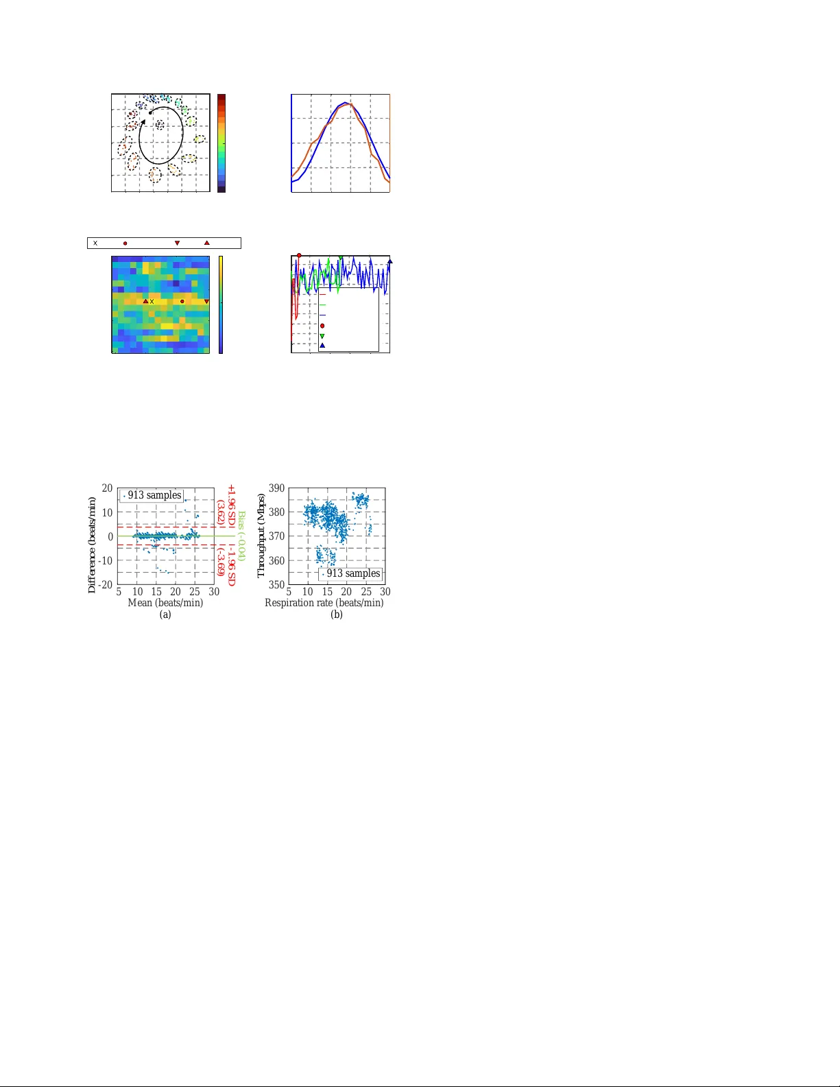
1 Acti v e RIS-Assisted MIMO System for V ital Signs Extraction: ISA C Modeling, Deep Learning, and Prototype Measurements De-Ming Chian, Member , IEEE , Chao-Kai W en, F ellow , IEEE , Feng-Ji Chen, Y i-Jie Sun, and Fu-Kang W ang, Member , IEEE Abstract —W e present the RIS-VSign system, an active re- configurable intelligent surface (RIS)-assisted multiple-input multiple-output orthogonal frequency division multiplexing (MIMO-OFDM) framework for vital signs extraction under an integrated sensing and communication (ISA C) model. The system consists of tw o stages: the phase selector of RIS and the extraction of vital signs. T o mitigate synchronization-induced common phase drifts, the difference of M ¨ obius transformation (DMT) is integrated into the deep learning framework, named DMTNet, to jointly configure multiple active RIS elements. Notably , the training data are generated in simulation without collecting real- world measurements, and the resulting phase selector is validated experimentally . For sensing, multi-antenna measurements are fused by the DC-offset calibration and the DeepMining-MMV processing with CA-CF AR detection and Newton’ s refinements. Prototype experiments indicate that active RIS deployment im- pro ves respiration detectability while simultaneously enabling higher -order modulation; without RIS, respiration detection is unreliable and only lower -order modulation is supported. Index T erms —Reconfigurable intelligent surface, integrated sensing and communication, M ¨ obius transf ormation, deep learn- ing. I . I N T RO D U C T I O N Driv en by the vision of sixth-generation (6G) wireless networks, ISA C is widely regarded as a cornerstone technol- ogy for enabling nativ e en vironmental perception and context awareness on top of high-throughput connectivity . By unifying sensing and communications, ISA C allows the two functions to share spectrum, wa veforms, and infrastructure, thereby meeting requirements for spectral and hardware efficienc y , low latency , high reliability , and deployability in realistic envi- ronments with blockage and multipath. Howe ver , in practical MIMO-OFDM systems, non-contact vital-sign sensing is often fragile due to weak micro-motion returns and synchronization impairments [1, 2], e.g., sampling frequency of fset (SFO), carrier frequency offset (CFO), and packet detection delay (PDD), which induce common phase drifts. T o be effecti ve in real-world ISA C systems, an RIS with the improvement ability of signal quality is suitable to sup- port fastly because of the low control overhead. Despite D.-M. Chian, C.-K. W en, and F .-J. Chen are with the Institute of Communi- cations Engineering, National Sun Y at-sen Univ ersity , Kaohsiung 804, T aiwan (e-mail: icefreeman123@gmail . com , c haok ai . wen@mail . nsysu . edu . t w , king19635@gmail . com ). Y .-J. Sun and F .-K. W ang are with the Department of Electrical Engi- neering, National Sun Y at-sen University , Kaohsiung 804, T aiwan (e-mail: spring1968bear@gmail . com , fkw@mail . ee . nsysu . edu . tw ). The source code for DMTNet will be released soon. V i t a l s i g n s s i g n a l s C o n s t e l l a t i o n h r ; t s h k ; t o h r ; k o h r ; k w l r ; k w Fig. 1. Application of RIS-VSign system. rapid progress, practical ISA C deployments face a persistent control bottleneck, particularly when a RIS is introduced as a programmable propagation interf ace [3]. Optimization- based phase configuration and pilot-intensive strategies can be computationally expensiv e and sensitive to phase drift, while purely data-dri ven solutions are often limited by the scarcity of labeled real-world measurements and potential domain mismatch between simulation and deployment. These challenges moti vate a model-informed learning approach that (i) reduces reliance on extensi ve calibration and data collec- tion, and (ii) maintains sensing robustness without sacrificing communication performance. The proposed RIS-VSign system consists of two steps: the phase selector of RIS and vital signs extraction. The key contributions of this study are as follows: • The proposed phase selector of RIS is based on the deep learning, and verified by the experiments. • W ithout using any real-world data, the training dataset is constructed based on a modified channel model [4] in the simulation. This implies that the proposed ISA C model is suitable for practical deployment. • W e ev aluate that the deployment of an acti ve RIS in a MIMO system simultaneously enhances the experimental performance of both sensing and communication. I I . I S AC M O D E L A. Practical Channel Model In Fig. 1, we consider a 5G NR-compatible OFDM down- link system, where a Tx equipped with T transmit antennas 2 and K active RIS elements serve an Rx with R receiv e antennas. W e assume that the echo signal from a person is only influenced by the RIS AM path, implying that the static channels do not contain vital signs. For respiration rate estimation, P consecutiv e packets are required [2]. The static components of the channel include the RIS SM path and the direct Tx-Rx path, while the dynamic components include the RIS AM path and the Doppler-affected reflections. The channel frequency response (CFR) of the static channel, observed at the r -th receive antenna from the t -th transmit antenna, is given by h r,t s . Moreov er, the CFR of the dynamic channel from the k -th active RIS element is given by h r,t d ,θ k = ( h r,k o + h r,k w e − j 2 π λ l r,k w ) a k h k,t o , (1) where a k = g k e − j θ k is the response of the k -th activ e RIS element with a constant gain g k and a phase shift θ k , h r,k o and h r,k w represent the complex attenuation components without and with vital signs, respectiv ely , l r,k w denotes the chest wall displacement, and λ is the wa velength. Howe ver , when applying the channel models in practical scenarios, an additional challenge arises: the lack of perfect time synchronization between Tx and Rx. This results in time- varying phase offsets [2], including SFO, CFO, and PDD. Since all Rx antennas share the same RF oscillator , they experience the same phase of fsets when receiving from a giv en Tx antenna, making the phase offset independent of the Rx antennas. Then, the CFRs of the static and dynamic channels considering time-varying phase offsets are giv en by c r,t s = h r,t s e − j ψ t and c r,t d ,θ k = h r,t d ,θ k e − j ψ t , respectively , where ψ t represents the time-varying phase offset. Assuming an unit transmission power per antenna, the signal power of the r -th receivr antenna with the t -th transmit antenna and the k -th activ e RIS element is defined as: E r,t θ k = | c r,t s + c r,t d ,θ k | 2 = | h r,t s + h r,t d ,θ k | 2 . (2) B. Optimization Model T o simplify the optimization problem of E , we consider a single RIS element. For the k -th acti ve RIS element with phase shift θ k , the maximization of (2) in a MIMO system is expressed as: R X r =1 T X t =1 E r,t θ k ≜ R X r =1 T X t =1 | h r,t s | 2 + | h r,t d ,θ k | 2 + 2 Re ( p r,t θ k ) , (3) where p r,t θ k = h r,t s ( h r,t d ,θ k ) ∗ is the complex inner product of h r,t s and h r,t d ,θ k . The first term in (3) is a constant. Moreover , the chest wall displacement during respiration is minimal, and the received signal magnitude from the human body is signif- icantly lower than that of the direct path, i.e., | h r,k o | > | h r,k w | in (1). Therefore, during the process of the maximization of (2), we reasonably assume that the second term in (3) is also constant. Then, the maximization of (3) is equiv alent to maximize the reward function: Q ( θ k ) = R X r =1 T X t =1 Re p r,t θ k . (4) Furthermore, the complex inner product p r,t θ k is rewritten as p r,t θ k = e j θ k h ( h r,t s ) ∗ h k,t o h r,k o + ( h r,t s ) ∗ h k,t o h r,k w e − j 2 π λ l r,k w i ∗ , (5) where the first and second terms in the square bracket cor- respond to the communication and sensing channels, respec- tiv ely . As shown in [3], RIS can enhance both communication and sensing in an ISAC frame work. Since (5) also captures this phenomenon, maximizing (3) improv es both communication and sensing performance. I I I . P H A S E S E L E C T O R T o eliminate time-varying offsets, two strategies are sum- marized in [2]. One utilizes an accurate phase information by using the direct coaxial connection between Tx and Rx. The other is based on the M ¨ obius transformation (MT) [1]. Because of the random location of Rx, the direct coaxial connection is not suitable for practical environments. W e let the r ′ -th receiv e antenna be the reference. Using the k -th RIS element with the θ k phase shift, the MT of total channel is applied and defined as follo ws: m r,t θ k ≜ ( c r ′ ,t s + c r ′ ,t d ,θ k ) / ( c r,t s + c r,t d ,θ k ) (6a) = ( A e j θ k + B ) / ( C e j θ k + D ) (6b) = M [ C e j θ k + D )] − 1 + ( A / C ) , (6c) where A = h r ′ ,t s , B = g k h k,t o ( h r ′ ,k o + h r ′ ,k w e − j 2 π λ l r ′ ,k w ) , C = h r,t s , D = g k h k,t o ( h r,k o + h r,k w e − j 2 π λ l r,k w ) , M = ( B C − AD ) / C , and B C − AD = 0 . (7) The MT of static channel is m r,t s = c r ′ ,t s /c r,t s = A / C . A. Predictor for One Element Next, we propose the selector of one RIS element’ s phase, based on the prediction of tendency in (4) for dif ferent θ k . Our predictor needs three inputs, m r,t s , m r,t θ k , and m r,t θ ′ k , assuming that | θ ′ k − θ k | = 180 ◦ . Because of the respiration’ s tiny vibration, we ignore the respiration’ s ef fect for m r,t θ k and m r,t θ ′ k during the RIS’ s controlling process. W e define the difference of M ¨ obius transformation (DMT) parameter as follo ws: δ r,t θ k ≜ m r,t θ k − m r,t s = M ( C e j θ k + D ) − 1 . (8) T o get p r,t θ k in (3), we use two DMT parameters, δ r,t θ k and δ r,t θ ′ k , and the following theorem can be found. Theor em 1: When | θ ′ k − θ k | = 180 ◦ , the complex inner product is p r,t θ k = Re p r,t θ k + j Im p r,t θ k , where Re p r,t θ k = | δ r,t θ ′ k | 2 − | δ r,t θ k | 2 4 | δ r,t θ ′ k | 2 E r,t θ k , (9a) j Im p r,t θ k = δ r,t θ ′ k ( δ r,t θ k ) ∗ − ( δ r,t θ ′ k ) ∗ δ r,t θ k 4 | δ r,t θ ′ k | 2 E r,t θ k . (9b) Pr oof 1: Please refer to Appendix for more details. 3 M a g n i t u d e I n p u t , 4 x 4 x 2 C o n c a t , 1 0 x 1 0 x 5 1 2 T C N N , 6 x 6 x 6 4 T C N N , 1 0 x 1 0 x 2 5 6 N o r m N o r m N o r m & R e L u T C N N , 8 x 8 x 1 2 8 N o r m & R e L u T C N N , 1 0 x 1 0 x 2 5 6 U p s a m p l e r A d d & R e L u F C & R e l u , 5 1 2 C N N , 8 x 8 x 1 0 2 4 C N N , 4 x 4 x 4 0 9 6 N o r m N o r m N o r m & R e L u C N N , 6 x 6 x 2 0 4 8 N o r m & R e L u C N N , 4 x 4 x 4 0 9 6 D o w n s a m p l e r A d d & R e L u & A v e r a g e P o o l i n g , 1 x 1 x 4 0 9 6 M u l t i - t a s k C l a s s i f i e r F C & R e l u , 5 1 2 F C & R e l u , 5 1 2 F C & O u t p u t , 1 6 F C & O u t p u t , 1 6 P h a s e I n p u t , 4 x 4 x 3 2 Fig. 2. DMTNet architecture for 4R4T MIMO system with 2 active RIS elements controlled by 4-bits DPSs. W ith the given p r,t θ k , we can predict the complex inner product p r,t θ ⋆ k of any θ ⋆ k ∈ [0 , 2 π ) . The corresponding magnitude and phase of p r,t θ ⋆ k are respecti vely expressed as | p r,t θ ⋆ k | = | p r,t θ k | , (10a) ∡ p r,t θ ⋆ k = θ ⋆ k − θ k + ∡ p r,t θ k . (10b) Finally , by substituting (10) into (4), b θ k = argmax θ ⋆ k Q ( θ ⋆ k ) is the selected phase of the k -th RIS element. Note that the complex inner product p r,t θ ⋆ k cannot be directly achiev ed by the complex inner product between the DMT parameter δ r,t θ k and the MT of static channel m r,t s without using Theorem 1. The reason is that δ r,t θ k still contains static component from D . B. DMTNet for T wo Elements Because of the complicated interference among RIS ele- ments, the extension of Theorem 1 for multiple RIS elements is non-trivial. Fortunately , the predictor in (10) describes the correlation between static and dynamic channels for all considering phase shifts. With DMT parameters of each RIS element, their correlations can be achieved and be utilized by the proposed deep learning, namely DMTNet, to select the phase of all RIS elements simultaneously . DMTNet architecture and the output size of each layer are shown in Fig. 2. T wo paths of inputs are the magnitude and phase of p r,t θ k , corresponding to the dimensions of R × T × S . For the phase of input, S = K D , where D is the number of controllable phases of DPS. Because of (10a), the magnitude of input for one of RIS element should be considered one times, i.e., S = K . DMTNet is composed of three components, a upsampler , a downsampler , and a multi-task classifier . The upsampler consists of transposed con volution neural networks (TCNNs) to upsample the much small dimension of input, compared with a common application of image. The do wnsampler con- sists of conv olution neural networks (CNNs) to e xtract feature. These two components are deployed by shortcut connections, inspired by the residual network to avoid the vanishing gradi- ent problem. Finally , the multi-task classifier is composed of fully-connect neural networks (FCs). The cross-entropy loss function is utilized to optimize classification model. I V . V I TA L S I G N S E X T R A C T I O N A. V ital Signs Signals The propose of vital signs extraction is to get the respiration rate ω . Fixing the phase shifts of all K activ e RIS elements, (6) at the p -th packet is redefined as follo ws: m r,t ω ,p = M ( C e j 2 π λ l r ′ ,k w + D ) − 1 + ( A / C ) , (11) where A = h r ′ ,t s + h k,t o h r ′ ,k o a k , B = h k,t o h r ′ ,k w a k , C = h r,t s + h k,t o h r,k o a k , D = h k,t o h r,k w a k e − j 2 π λ ∆ , M = ( B C − A D ) / C , B C − A D = 0 , (12) ∆ = l r,k w − l r ′ ,k w approaches to a constant because the r -th and r ′ -th antennas are close, and the displacements l r ′ ,k w and l r,k w change with the respiration activity at the p -th packet. [1] verified that m r,t ω ,p with vital signs changes following a circle in complex plane. Then, the respiration is described by the phase of m r,t ω ,p . Moreover , except the considering r -th receiv e antenna of m r,t ω ,p , the other antennas can be the reference, denoted as the r ′ -th receive antenna. Hence, the phase of (11) has R − 1 combinations. Ho wev er, when the conjugate of m r ′ ,t ω ,p is m r,t ω ,p , i.e., m r ′ ,t ω ,p = 1 /m r,t ω ,p , they are dependent on the same displacement. One of them needs to be considered. For (11), the phase vector of all necessary combinations is denoted as ∡ m r,t ω ,p ∈ R ( R − 1) / 2 . When the tester’ s respiration rate is ω , the corresponding total channel from the t -th transmit antenna to the r -th receive antenna at the p -th packet is denoted as c r,t ω ,p . The amplitude of c r,t ω ,p is also dependent on the displacement of chest wall, and is denoted as | c r,t ω ,p | . The average of | c r,t ω ,p | and ∡ m r,t ω ,p ov er F subcarriers are applied and denoted as | c r,t ω ,p | and ∡ m r,t ω ,p , respectiv ely . For the t -th transmit antenna, the average amplitude vector and the av erage phase vector for R recei ve antennas are respectively expressed as | c t ω ,p | = [ | c 1 ,t ω ,p | , . . . , | c R,t ω ,p | ] T ∈ R R , (13a) ∡ m t ω ,p = [ ∡ m 1 ,t ω ,p T , . . . , ∡ m R,t ω ,p T ] T ∈ R R ( R − 1) / 2 . (13b) For T transmit antennas and P packets, the vital signs matrix is Y vs = [ y 1 vs , . . . , y N vs ] T ∈ R N × P , where the n -th vital signs vector y n vs is the stack of (13a) and (13b) from all transmit antennas, and N ≜ T R ( R + 1) / 2 . Moreov er , Y vs can be regarded as N sensors with P sampling points in the measurement area. Because the respiration activity has the periodicity , the model of the reflected signal from the human subject can be 4 simplified as a complex exponential function of time. The n -th vital signs vector with the frequency ω is modeled as y n vs = g n vs s vs ( ω ) + ϵ n vs , (14) where g n vs is the complex coef ficient of the vital sign, s vs ( ω ) = [1 , e j ω , . . . , e j ω ( P − 1) ] T ∈ C P is the exponential vector , and ϵ n vs ∈ C P is the noise vector with the DC offset. B. V ital Signs Estimation Our signal processing consists of two steps: DC offset calibration and vital signs extraction. The DC offset cali- bration is introduced by removing y n vs with the 2 -nd degree polynomial curve fitting. For the vital signs extraction, the design is difficult in a MIMO system due to two reasons. Firstly , the number of the equiv alent sensors N is large, e.g., N = 40 for the 4R4T MIMO system. Secondly , because the vital sign signals are from the different propagation paths, they are corresponding to the obviously different power levels. Therefore, the challenge is to extract the vital signs signals with the different signal qualities. According to this two reasons, the data fusion algorithm, namely DeepMining-MMV [5], is applied for the vital signs extraction. Three stages are utilized in DeepMining-MMV . W e modify the first stage to detect vital signs and use the second and third stages to estimate them. Firstly , we merge the normalized frequency spectrums of the reflected signals into one spectrum. T o determine whether the subjects exist and are stable in the measurement area or not, the cell-av eraging constant false alarm rate (CA-CF AR) [6] algorithm is utilized for the vital sign detection. If the vital signs is detected successfully , the frequency corresponding to the strongest power in the spectrum is configured to the initial frequency b ω . Secondly , the complex coefficient c g n vs is refined by the least-squares (LS) estimator with the gi ven initial frequency . Thirdly , the initial frequency is refined by using the Newton’ s method to the normalized LS estimator based on the power of residual signals | σ n vs | 2 , where the residual signals are achieved by y n vs := y n vs − c g n vs s vs ( b ω ) . The third stage is equiv alent to minimizing the cost function J ( c g vs , b ω ) = N X n =1 − 2 Re ( c g n vs y n vs H s ( b ω )) + | c g n vs | 2 ∥ s ( b ω ) ∥ 2 | σ n vs | 2 , (15) V . P E R F O M A N C E E V A L UAT I O N A. T raining Results W e modify the v erified RIS’ s model [4] to a 4R4T MIMO system in the scenario containing scattering clusters based on a large-scale fading. T wo RIS elements is applied, and the number of controllable phases D is 16. The training and testing datasets are generated by this channel model without noise. The number of them are 180,000 and 20,000 samples, respectiv ely . The operating frequency of single subcarrier is 3.65 GHz. The optimized loss and accuracy of DMTNet are shown in Fig. 3(a), and the errors of two DPSs are shown in Fig. 3(b). Although the accuracy of each DPS is only greater than 60 % , approximate 95.4 % of the samples hav e ( b ) 8 8 . 9 % 9 5 . 4 % ( a ) E p o c h 1 6 1 1 1 6 2 1 2 6 3 1 3 6 L o s s A c c u r a c y ( % ) 0 3 6 9 1 2 0 2 0 4 0 6 0 8 0 T e s t T r a i n T r a i n / R I S 1 T r a i n / R I S 2 T e s t / R I S 1 T e s t / R I S 2 E r r o r o f 2 - n d D P S s t a t e E r r o r o f 1 - s t D P S s t a t e 0 2 4 6 8 0 2 4 6 8 0 . 0 0 . 1 0 . 2 0 . 3 0 . 4 0 . 4 5 Fig. 3. DMTNet: (a) Loss and accuracy , and (b) error of testing dataset. ( a ) ( b ) ( c ) F r e q u e n c y ( G H z ) S p a r a m e t e r s ( d B ) - 5 0 - 4 0 - 3 0 - 2 0 - 1 0 0 3 . 2 3 . 4 3 . 6 3 . 8 4 . 0 P o r t 1 P o r t 2 Á L N A 4 - b i t s D P S V c c R e l a y M e a s . S 1 1 M e a s . S 2 2 M e a s . S 1 2 T r a n sm i t t e r R e c e i v e r 1 . 5 m 2 m 2 . 3 m B e l t 4 x 4 R IS a r r a y Fig. 4. (a) Structure of acti ve RIS element, (b) measured S parameters of antenna pair , and (c) experimental scenario. phase selection errors less than 2. This indicates that, for 95.4 % of the samples, the phase differences from the optimal values are less than 45 ◦ when considering two RIS elements simultaneously . B. Measurements The structure of one acti ve RIS element is shown in Fig. 4(a), composed of a self-decoupled antenna pair with two feeding ports, a LNA with an approximate 20 dB power gain, a 4-bits DPS with 16 phase shift states in 22.5 ◦ steps, and a relay . T wo feeding ports perform the function of transmit and recei ve signals, respectiv ely . They are connected to the different other antenna pairs to enhance the isolation among all ports deployed on a RIS array . Moreover , a self-decoupled antenna pair is operated in the frequency range of 3.4-3.8 GHz. In Fig. 4(b), their measured reflection and transmission coefficients in the operating band are less than -10 dB and -20 dB, respecti vely . Finally , the 4 × 4 activ e RIS array is utilized in the ISA C application, shown in Fig. 4(c), to improv e the signal quality degraded by the obstacle. Our 4R4T MIMO system follows that in [7] and transmits 5G OFDM signals in the 3.7-3.72 GHz band. Firstly , we verify the predictor in Section III-A. T o simplify and strengthen the phenomenon, all RIS elements are specially configured to the same phase shift state, and Rx is in front of the RIS. By turning off all relays, the MT of static channel m r,t s is achieved. When we turn on all relays and iterate through the phase shift states, the MT of total channels for all states m r,t θ k are achieved. For the one subcarrier’ s channel from the 1-st transmit antenna to the 1-st receiv e antenna, the MT of different states’ channels with 10 continuous packets are shown in Fig. 5(a). The stable and reliable channel information is achiev ed by av eraging continuous packets for each state. 5 DMT process GS process CSM process DMT final GS final state CSM final (a) (b) (d) (c) 1 6 11 16 Left RIS group -1.0 -0.5 0 -1.5 -0.5 1.5 2.0 Real -2.5 -1.5 -0.5 0.5 Imaginary Off 8 16 1 States 0.5 Measured Signal Power (dB) -8 -4 4 8 1 4 7 10 13 16 RIS state -22 -21 -19 -18 1 6 11 16 Right RIS group Relative Signal Power Relative Signal Power Iteration (times) 1 13 26 39 52 65 Off 1 16 -1.0 -0.8 -0.6 -0.4 -0.2 0 0 -20 GS CSM DMTNet Max Equation (4) Fig. 5. (a) m 1 , 1 s and m 1 , 1 θ k for all states of DPS. (b) Predicted reward and measuremed signal power . (c) All combinations and (d) controlling processes by using different algorithms. ( a ) ( b ) M e a n ( b e a t s / m i n ) D i f f e r e n c e ( b e a t s / m i n ) 5 1 0 1 5 2 0 2 5 3 0 - 2 0 - 1 0 0 1 0 2 0 B i a s ( - 0 . 0 4 ) + 1 . 9 6 S D ( 3 . 6 2 ) - 1 . 9 6 S D ( - 3 . 6 9 ) 9 1 3 s a m p l e s 3 5 0 3 6 0 3 7 0 3 8 0 3 9 0 T h r o u g h p u t ( M b p s ) R e s p i r a t i o n r a t e ( b e a t s / m i n ) 5 1 0 1 5 2 0 2 5 3 0 9 1 3 s a m p l e s Fig. 6. ISA C performance: (a) Bland–Altman plot of respiration rate and (b) throughput in different respiration rates. According to | θ ′ k − θ k | = 180 ◦ , the DMT parameters of the 1- st and 9-th phase shift states are utilized for the predictor , and we will get the reward of each state. By summing across all subcarriers, the rewards are shown in Fig. 5(b). Because the predicted re wards closely match the measured signal po wer for each state, the validity of the proposed predictor is confirmed. Secondly , with the results of predictor, DMTNet is e valuated in Fig. 5(c). The elements of RIS array are di vided into left and right groups. The elements in the same group have the identical phase shift states. For all combinations of states, the relative signal power is shown in Fig. 5(c). T wo other controlling algorithms are included in the discussion. One is the greedy searching (GS) algorithm [4]; the other is conditional sample mean (CSM) algorithm [8], based on the phase expectation of each group. The final states of three algorithms are close to the optimum state. Howe ver , their controlling processes are shown in Fig. 5(d), and the huge difference in their number of iterations can be observed. The number of iterations with DMTNet, GS, and CSM are 5, 32, and 64, respecti vely . After applying the phase selector of DMTNet, the vital signs extraction is utilized. W e use a respiration belt, as a contact method, to compare with our noncontact method. Because a high correlation does not imply a good agreement, we use the Bland–Altman plot to describe an agreement and shown in Fig. 6(a). The samples of over 95.7 % fall within 1.96 standard deviations from the mean. Because of a good agreement between two methods, a high accuracy of our method is indicated. Moreover , our MIMO system can support 64 QAM and achiev e the maximum throughput of about 388 Mbps in Fig. 6(b). Contrarily , without RIS, the system cannot detect respiration rate, and the MIMO system only supports 16 QAM. V I . C O N C L U S I O N The proposed RIS-VSign system demonstrates an ISA C framew ork in a 5G NR–compatible MIMO-OFDM system by combining DMTNet-based activ e-RIS phase control with DeepMining-MMV -based respiration estimation. The exper - imental results indicate that deploying an active RIS can simultaneously enhance sensing reliability and communication performance. In contrast, the RIS-free system fails to reliably detect respiration and supports only lo wer-order modulation. A P P E N D I X : P RO O F O F T H E O R E M 1 W ith (3) and (8), we hav e | δ r,t θ k | − 2 = E r,t θ k |M| − 2 . Then, | δ r,t θ k | − 2 − | δ r,t θ ′ k | − 2 = 2[ Re ( p r,t θ k ) − Re ( p r,t θ ′ k )] |M| − 2 . Assuming that | θ ′ k − θ k | = 180 ◦ , we can get Re ( p r,t θ ′ k ) = − Re ( p r,t θ k ) . Thus, 4 Re ( p r,t θ k ) = |M| 2 ( | δ r,t θ k | − 2 − | δ r,t θ ′ k | − 2 ) = |M| 2 ( | δ r,t θ ′ k | 2 − | δ r,t θ k | 2 ) / ( | δ r,t θ k | 2 | δ r,t θ ′ k | 2 ) , where |M| 2 = | δ r,t θ k | 2 E r,t θ k . Finally , the (9a) of Theorem 1 is prov ed. (8) can be expressed as ( δ r,t θ k ) − 1 M = C e j θ k + D . When | θ ′ k − θ k | = 180 ◦ , we get ( C e j θ k + D )( C e j θ ′ k + D ) ∗ = −|C | 2 + |D | 2 + 2 j Im ( p r,t θ k ) = |M| 2 [ δ r,t θ k ( δ r,t θ ′ k ) ∗ ] − 1 . Then, 4 j Im ( p r,t θ k ) = |M| 2 { [ δ r,t θ k ( δ r,t θ ′ k ) ∗ ] − 1 − [ δ r,t θ ′ k ( δ r,t θ k ) ∗ ] − 1 } = |M| 2 [ δ r,t θ ′ k ( δ r,t θ k ) ∗ − ( δ r,t θ ′ k ) ∗ δ r,t θ k ] / ( | δ r,t θ k | 2 | δ r,t θ ′ k | 2 ) , where |M| 2 = | δ r,t θ k | 2 E r,t θ k . Finally , the (9b) of Theorem 1 is proved. R E F E R E N C E S [1] Y . Zeng et al ., “FarSense: Pushing the range limit of W iFi-based respi- ration sensing with CSI ratio of two antennas, ” in Proc. A CM Interact., Mobile, W earable Ubiquitous T echnol. , vol. 3, no. 3, Ne w Y ork, NY , USA, Sep. 2019, pp. 1–26. [2] Y . He, Y . Chen, Y . Hu and B. Zeng, “W iFi V ision: Sensing, recognition, and detection with commodity MIMO-OFDM W iFi, ” IEEE Internet Things J . , vol. 7, no. 9, pp. 8296–8317, Sep. 2020. [3] S. P . Chepuri et al ., “Integrated sensing and communications with reconfigurable intelligent surfaces: From signal modeling to processing, ” IEEE Signal Process. Mag. , vol. 40, no. 6, pp. 41–62, Sep. 2023. [4] D.-M. Chian et al. , “A novel channel model for reconfigurable intelligent surfaces with consideration of polarization and switch impairments, ” IEEE T rans. Antennas Pr opag. , vol. 72, no. 4, pp. 3680–3695, Apr . 2024. [5] D.-M. Chian et al ., “V ital signs identification system with Doppler radars and thermal camera, ” IEEE Tr ans. Biomed. Circuits Syst. , vol. 16, no. 1, pp. 153–167, Feb. 2022. [6] M.A. Richards, Fundamentals of Radar Signal Processing , Thir d Edition . McGraw-Hill Education, 2022. [7] D.-M. Chian et al ., “Active RIS-assisted MIMO-OFDM system: Analyses and prototype measurements, ” IEEE Commun. Lett. , vol. 28, no. 1, pp. 208–212, Jan. 2024. [8] S. Ren et al ., “Configuring intelligent reflecting surface with performance guarantees: Blind beamforming, ” IEEE T rans. W ireless Commun. , vol. 22, no. 5, pp. 3355–3370, May . 2023.
Original Paper
Loading high-quality paper...
Comments & Academic Discussion
Loading comments...
Leave a Comment