Joint beamforming and mode optimization for multi-functional STAR-RIS-aided integrated sensing and communication networks
This paper investigates the design of integrated sensing and communication (ISAC) systems assisted by simultaneously transmitting and reflecting reconfigurable intelligent surfaces (STAR-RISs), which act as multi-functional programmable metasurfaces …
Authors: Ziming Liu, Tao Chen, Giacinto Gelli
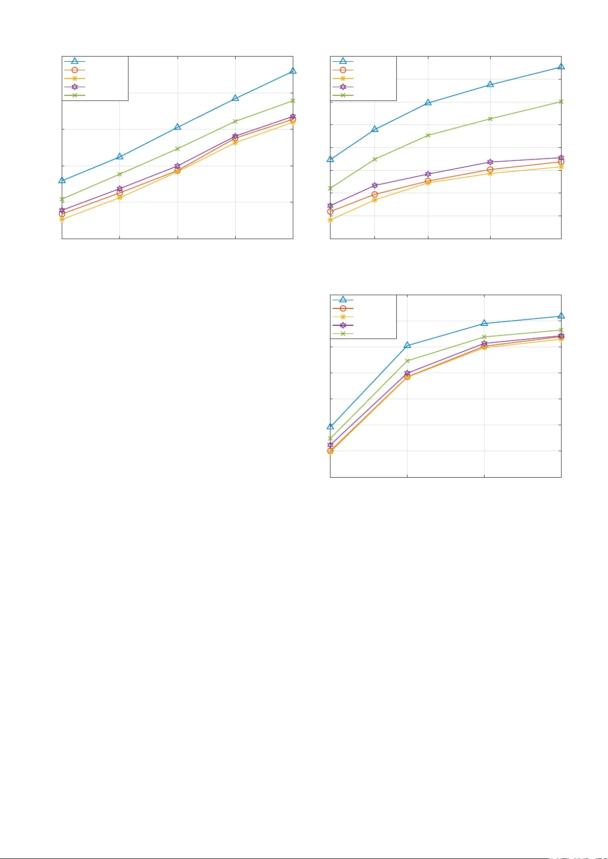
1 Joint beamforming and mode optimization for multi-functional ST AR-RIS-aided inte grated sensing and communication networks Ziming Liu, Member , IEEE , T ao Chen, Member , IEEE , Giacinto Gelli, Senior Member , IEEE , V incenzo Galdi, F ellow , IEEE , and Francesco V erde, Senior Member , IEEE Abstract —This paper in vestigates the design of integrated sensing and communication (ISA C) systems assisted by simulta- neously transmitting and reflecting reconfigurable intelligent sur- faces (ST AR-RISs), which act as multi-functional programmable metasurfaces capable of supporting concurrent communication and sensing within a unified architecture. W e propose a two-stage ISA C protocol, in which the pr eparation phase perf orms dir ection estimation for outdoor users located in the r eflection space, while maintaining communication with both outdoor and indoor users in the transmission space. The subsequent communication phase exploits the estimated directions to enhance information transfer . The directions of outdoor users are modeled as Gaussian random v ariables to capture estimation uncertainty , and the corresponding a verage communication performance is incorpo- rated into the design. Building on this framework, we formulate a performance-balanced optimization pr oblem that maximizes the communication sum-rate while guaranteeing the required sensing accuracy, jointly determining the beamforming vectors at the base station (BS), the ST AR-RIS transmission and reflec- tion coefficients, and the metasurface partition between energy- splitting and transmit-only modes. The physical constraints of ST AR-RIS elements and the required sensing performance are explicitly enforced. T o address the non-con vex nature of the problem, we combine fractional programming, Lagrangian dual ref ormulation, and successive conv ex approximation. The binary metasurface partition is ultimately reco vered via continuous relaxation followed by projection-based binarization. Numeri- cal results demonstrate that the proposed design achieves an effective trade-off between sensing accuracy and communication throughput, by significantly outperforming conventional ST AR- RIS-aided ISA C schemes. Such characteristics make the pr oposed architectur e well suited for dense Internet-of-Things deployments in smart en vironments, where energy-efficient connectivity and device localization must be jointly supported. Index T erms —Beamforming optimization, direction-of-arriv al (DO A) estimation, fractional programming, integrated sens- ing and communication (ISA C), multi-functional programmable metasurfaces, simultaneously transmitting and reflecting (ST AR) metasurface, sixth-generation (6G) networks, successive con vex Manuscript receiv ed February 18, 2026; revised xx yy , 2026; accepted xx yy , 2026. The associate editor coordinating the revie w of this paper and approving it for publication was Dr . xx yy . ( Corresponding author: Fr ancesco V er de) Z. Liu and T . Chen are with the College of Information and Communication Engineering of Harbin Engineering Univ ersity , Harbin, 150001 China (e- mail: lzmfred@hrbeu.edu.cn, chentao@hrbeu.edu.cn). G. Gelli is with the Department of Electrical Engineering and Information T echnology , Univ ersity Federico II, Naples I-80125, Italy (e-mail: gelli@unina.it). V . Galdi is with the Department of Engineering, University of Sannio, Benev ento I-82100, Italy (e-mail: vgaldi@unisannio.it). F . V erde is with the Department of Engineering, University of Campania Luigi V an vitelli, A versa I-81031, Italy (e-mail: francesco.v erde@unicampania.it). approximation (SCA). I . I N T RO D U C T I O N M ET ASURF A CES are artificial electromagnetic (EM) structures composed of subwa velength elements (“meta-atoms”) possibly integrated with tunable microelec- tronic components, such as diodes and v aractors, which en- able programmable control over the amplitude, phase, and polarization of incident wav es [1]. When empowered with reconfigurability , these structures give rise to reconfigur able intelligent surfaces (RISs) , which have emerged as a key en- abler for next-generation wireless networks due to their ability to reshape the propagation environment in a software-defined manner [2]–[4]. By dynamically manipulating the reflected or transmitted wav efronts, RISs allo w the establishment of fa vorable communication links, mitigation of blockages, and enhancement of coverage in complex propagation scenarios [5]–[7]. Owing to their lo w po wer consumption, compact form factor , and deployment flexibility , RISs are particularly attractiv e for integration into urban infrastructures, vehicles, and b uildings, thus supporting the vision of environment-a ware and user-centric wireless networks [8]–[11]. Despite their advantages, con ventional RIS architectures typically rely on reflectiv e elements, which inherently limit their angular cov erage to a single half-space. This constraint restricts their applicability in scenarios where users are dis- tributed on both sides of the surface. T o overcome this limita- tion, simultaneously tr ansmitting and r eflecting r econfigur able intelligent surfaces (ST AR-RISs) hav e been recently proposed [12]–[14]. By le veraging adv anced meta-atom designs and interlayer structures, ST AR-RISs are capable of concurrently reflecting and transmitting incident signals, thereby enabling full-space EM control [15], [16]. This unique capability makes ST AR-RISs a promising solution for supporting heterogeneous users located in distinct spatial regions, such as indoor and outdoor environments separated by a building facade. ST AR-RISs can operate under dif ferent working modes , including energy splitting (ES), mode switching (MS), time division (TD), polarization division (PD), and frequency di- vision (FD) [17], [18]. Among these, the ES mode has receiv ed the most attention in the literature due to its ability to simultaneously support transmission and reflection while respecting energy conserv ation principles [19]–[25]. In this 0000–0000/00$00.00 © 2026 IEEE 2 mode, the transmitted and reflected signals are intrinsically coupled through both amplitude and phase constraints. Other modes, such as MS and TD [26], can be interpreted as special cases or extensions of the ES mode with additional constraints, while PD and FD impose stringent requirements on signal polarization or frequency selectivity [27], [28], and hav e therefore received limited attention in the literature. In parallel with the dev elopment of programmable meta- surfaces, inte gr ated sensing and communication (ISAC) has emerged as a fundamental paradigm for sixth-generation (6G) wireless networks [29], [30]. ISA C aims to unify sensing and communication functionalities within a single system, enabling spectrum- and hardware-efficient operation. ST AR- RISs are particularly well suited for ISA C applications, as their full-space control capability allows simultaneous information deliv ery and en vironmental sensing in different spatial regions. Recent works have inv estigated ST AR-RIS-assisted ISA C sys- tems under v arious assumptions [31]–[34]. Howe ver , most ex- isting designs rely on idealized knowledge of user locations or directions and do not explicitly account for the intrinsic uncer- tainty arising from sensing and estimation processes. Indeed, in practical ISA C deployments, especially in dynamic outdoor en vironments, user positions or directions are not perfectly known and must be inferred through sensing mechanisms. Prior studies [35]–[38] have shown that direction-of-arriv al (DO A) estimation accuracy in metasurface-assisted systems is fundamentally limited by noise, propagation conditions, and hardware constraints. Moreov er , most existing works focus on optimizing beamforming and ST AR-RIS coefficients within a single transmission stage. In contrast, the protocol-lev el design (i.e., the joint optimization of system parameters across multiple phases within a slot) accounting for the distinct roles of sensing- and communication-oriented signaling has receiv ed comparativ ely limited attention. A. Contribution This paper in vestigates a ST AR-RIS-aided ISA C system deployed on the fac ¸ ade of a smart building (see Fig. 1), where a base station (BS) serv es both indoor and outdoor users while sensing the directions of outdoor users through dedicated sensors mounted on the ST AR-RIS. Beyond con ventional broadband services, the proposed ST AR-RIS-assisted ISA C framew ork is particularly well suited to support Internet-of- Things (IoT) ecosystems in smart cities [39]. Its low-po wer , compact metasurface deployment on building facades enables wide-area, environment-a ware connectivity and accurate de- vice localization - supporting IoT use cases such as large-scale sensor networks, crowd and traf fic monitoring, asset tracking, and energy-efficient massi ve access in dense urban scenarios. W e propose a two-stage ISA C protocol operating on a slot- by-slot basis. In the preparation phase, the system performs DO A estimation for outdoor users while simultaneously sup- porting downlink communication to all users. In the subse- quent communication phase, the estimated angular information is exploited to refine the transmission strategy and enhance sum-rate communication performance. In oder to explicitly capture the effect of sensing uncertainty , the directions of BS Ref l ec t i o n Sp ace U s ers T ran s m i s s i o n Sp ace U s ers ST A R - RIS Sen s o rs Figure 1: Illustration of the considered ST AR-RIS-aided net- work. outdoor users are modeled as Gaussian random variables whose variances are determined by estimation accuracy , and the average communication and sensing performance is incor- porated into the system design. Building on this framew ork, we formulate a performance- balanced optimization problem that jointly designs the base station beamforming vectors, the ST AR-RIS transmission and reflection coefficients in both stages, and the metasurface partition between ES and transmit-only (TO) modes, where each element fully transmits the incident signal without power splitting. The physical feasibility constraints of ST AR-RIS elements, including energy conservation and phase coupling, are explicitly enforced, together with sensing-quality require- ments. T o tackle the resulting non-con ve x and mix ed dis- crete–continuous optimization problem, we deriv e an effi- cient solution based on fractional programming, Lagrangian dual reformulation, successiv e conv ex approximation, and semidefinite relaxation. The binary metasurface partition is ultimately recov ered through a continuous relaxation follo wed by projection-based binarization. Simulation results demon- strate that the proposed design achieves a fa v orable trade- off between sensing accuracy and communication throughput, while exhibiting robustness against direction estimation errors. Compared with con ventional ST AR-RIS-aided ISA C schemes that neglect uncertainty or multi-functional operation, the pro- posed framew ork yields significant performance gains under both ideal and imperfect sensing conditions. B. Organization The remainder of the paper is organized as follows. Sec- tion II presents the system model and the basic assump- tions considered throughout the paper , including the ST AR- RIS architecture, the two-stage ISAC protocol, and the DO A uncertainty model for outdoor users. Section III formulates the optimization problem and derives the proposed algorithmic so- lution. Section IV provides numerical results and performance comparisons. Section V concludes the paper . I I . S Y S T E M M O D E L A N D BA S I C A S S U M P T I O N S As shown in Fig. 1, we consider an ISA C system, where sensing and communication tasks are assisted by a ST AR-RIS, 3 placed on the outer wall of a smart building, which is a realistic deployment strategy in future smart cities and 6G intelligent en vironments [40]. Smart buildings already integrate multi- ple technologies (e.g., heating, ventilation, air conditioning, lighting, and surveillance). In accordance with the emerging paradigm of user-centric and en vironment-a ware netw orks, we en vision a smart building additionally incorporating radio- frequency (RF) sensors aimed at detecting and localizing low- mobility users in the vicinity of the f acade [39]. Sensors on the wall ha ve direct visibility to ward the front zone of the b uilding, making them ideal for real-time, accurate localization, which is a crucial issue in many applications of en vironmental sensing, such as, e.g., crowd monitoring, pedestrian flow analysis, pub- lic transportation systems monitoring [41], and traffic control. The considered ISA C system consists of a BS, equipped with a uniform linear array (ULA) of M antennas, which trans- mits in downlink to K users. The ST AR-RIS is composed by a uniform planar array (UP A) of N = N x × N z reconfigurable elements, which enable full-space control. The impinging EM signals can be reflected from the ST AR-RIS for outdoor sens- ing and communication, and can be simultaneously transmitted (i.e., refracted) for indoor information transfer . W e assume that K R single-antenna users reside in the outdoor reflection side ( reflection space ) and K T single- antenna users lie in the indoor transmission side ( tr ansmis- sion space ). Hereinafter , for the sake of conciseness, the set K ≜ { 1 , 2 , . . . , K } , with K ≜ K T + K R , collects the indexes of both indoor and outdoor receiv ers: the first K T entries of K (belonging to the set K T ≜ { 1 , 2 , . . . , K T } ) identify the indoor terminals, whereas the remaining K R ones (belonging to the set K R ≜ { K T + 1 , K T + 2 , . . . , K } ) are used to index the outdoor ones. Similarly to [31], we consider a sensing-at- ST AR-RIS structure, where a dedicated low-cost sensor with a ULA consisting of N s elements is mounted on the ST AR-RIS. The direct BS–to-user links are assumed ne gligible (in num- ber) compared to the ST AR-RIS-assisted paths, due to severe blockage and unfav orable propagation conditions, typical of indoor and outdoor urban en vironments. Such an assumption is supported by standardized models and field measurements at mmW a ve or sub-THz frequencies, which sho w that building penetration loss and blockage effects may render indoor paths negligible. For example, 3GPP TR 38.901 [42] and ITU-R P .2109 [43] report penetration losses often exceeding 30 − 60 dB for common construction materials, while extensiv e urban measurements (e.g., NYU W ireless [44]) confirm that sev ere strong attenuation (e.g., by buildings or foliage) is not rare in dense urban outdoor deployments. The observation interval is divided into time slots of dura- tion T over which the channels and direction parameters of the users are assumed to be constant. All the relev ant channels are modeled as frequency-flat (i.e., the channel delay spread is small relativ e to the in verse signal bandwidth), as detailed in Subsection II-C. During the t -th slot, with t ∈ N 0 , the direction of the k -th user is described by d k ( t ) ≜ [ ϕ k ( t ) , φ k ( t )] T ∈ R 2 , where ϕ k ( t ) and φ k ( t ) are the elev ation and azimuth angles between the k -th user and the ST AR-RIS, respecti vely , for k ∈ K . W e assume perfectly known directions for indoor users [45], i.e., d 1 ( t ) , d 2 ( t ) , . . . , d K T ( t ) are treated as known Preparation Communication the t- th slot …… …… …… …… …… …… …… …… …… …… T 1 T Reflect and Transmit Only Transmit Figure 2: W orking modes of the ST AR-RIS in a generic slot. deterministic parameters in the optimization process. Such an assumption is justified by the fact that indoor users are typically connected via fixed access points with well-defined geometric layouts and, thus, their positions and orientations can be precisely estimated through existing localization and tracking systems. Moreov er , since the indoor propagation en vironment is quasi-static, the directions of indoor users are often stable ov er long time interv als. Con versely , the directions of outdoor users cannot be assumed as perfectly known, since outdoor en vironments are typically dynamic and unpredictable, making directions of outdoor users observable only through estimation mechanisms working on a slot-by-slot basis [46]. As shown in Fig. 2, the time slot t is divided into two subslots. The first one, of duration η T (with 0 ≤ η ≤ 1 being a fixed system parameter) is referred to as the pr eparation phase or stage , and is dedicated to sensing of the outdoor users, i.e., estimation of the directions d K T +1 ( t ) , d K T +2 ( t ) , . . . , d K ( t ) , and do wnlink communication to both indoor and outdoor users. During such a phase, reflection signals to wards the outdoor users are realized by the ST AR-RIS relying on the es- timates of the outdoor user directions obtained in the previous ( t − 1) -th slot (see Subsections II-C and II-E). Capitalizing on the estimates b d K T +1 ( t ) , b d K T +2 ( t ) , . . . , b d K ( t ) of the outdoor user directions obtained at the end of the preparation stage during the t -th slot, the remaining part of the slot of duration (1 − η ) T , referred to as communication phase/stage , is only dev oted to information transfer to all the users. As the ISAC system operates on a slot-by-slot basis, the analysis is restricted, without loss of generality , to a generic time slot. Accordingly , in the following the explicit depen- dence on the slot index t is omitted, unless otherwise indicated. A. Signal transmitted by the BS W e assume that sensing of the outdoor de vices is performed using the same signals employed for communication. This design choice is primarily motiv ated by the need to enhance spectral and hardware efficiencies, thereby minimizing band- width consumption, reducing system complexity , and lo wering implementation costs. During a gi ven time slot, the signal transmitted by the BS to the k th user in the i -th symbol interv al 4 can be written as x ( i ) = W s ( i ) = K X k =1 w k s k ( i ) , for i ∈ I ≜ { 0 , 1 , . . . , I − 1 } (1) where I is the number of symbols packed by the BS in a slot, W = [ w 1 , w 2 , . . . , w K ] ∈ C M × K represents the beamform- ing matrix and s ( i ) = [ s 1 ( i ) , s 2 ( i ) , . . . , s K ( i )] T ∈ C K denotes the signal vector , with s k ( i ) ( k ∈ K ) denoting the signal destined to the k -th user . In the sequel, we assume that s ( i ) can be modeled as a zero-mean complex circular vector ha ving cov ariance matrix E [ s ( i ) s H ( i )] = I K , which is statistically independent of the information-bearing symbols transmitted in other symbol interv als and slots. This signal model remains valid across all operational modes of the system. Using (1), the total power transmitted by the BS is P ≜ E [ ∥ x ( i ) ∥ 2 ] = tr ( W W H ) . (2) B. ST AR-RIS model W e assume that the ST AR-RIS is located in the far-field region of the BS and, additionally , all the users are in the far -field region of the ST AR-RIS. Moreover , we make the customary assumption that the one-sided bandwidth B of the ISA C signal is much smaller than its carrier frequency f 0 , thereby ensuring that the responses of the BS array and RIS are essentially constant within the frequency interval ( f 0 − B 2 , f 0 + B 2 ) . Finally , we consider a linearly polarized (horizontally or vertically) wireless signal, and we neglect cross-polarization ef fects and losses. The RIS elements, which are arranged in a rectangular grid, are indexed row by ro w . If they are designed such that to ensure weak dependence on the incidence direction [47], the EM response of its n -th element during the preparation stage is described by the transmission coefficient ϕ p T ,n = β p T ,n e j θ p T ,n (3) where j ≜ √ − 1 denotes the imaginary unit, controlling the transmitted fraction of the incident wave, and the reflection coefficient ϕ p R ,n = β p R ,n e j θ p R ,n (4) dictating the reflected fraction of the incident wa ve, where β p a ,n and θ p a ,n represent the amplitude and phase of the n -th element during the preparation stage, respectiv ely , for a ∈ { T , R } and n ∈ N ≜ { 1 , 2 , . . . , N } . The coupling between the reflection and transmission coefficients of each element depends on the operational mode of the ST AR-RIS. During the preparation stage, each element of the ST AR- RIS might independently work either in ES or TO modes [17]. In the case of ES, the signal transmitted by the n -th element of the BS is simultaneously reflected outdoor and transmitted indoor in the preparation stage. T w o constraints hav e to be fulfilled for passi ve lossless ST AR-RIS in ES mode. First, according to the law of ener gy conservation [48], the incident signal’ s power on the element must be equal to the sum of reflected and transmitted powers. Second, since the scalar electric and magnetic impedances of the n -th element of the ST AR-RIS should ha ve purely imaginary values, the phases of the reflection and transmission coefficients obey cos( θ p R ,n − θ p T ,n ) = 0 [20]. T o be more specific, the two constraints in ES mode can be stated as follows β p R ,n 2 + β p T ,n 2 = 1 (5) θ p R ,n − θ p T ,n = π 2 or 3 π 2 . (6) Alternativ ely , for the TO configuration, the n -th element of the ST AR-RIS operates during the preparation stage in transmission mode solely , i.e., β p R ,n = 0 and β p T ,n = 1 (7) θ p T ,n ∈ [ − π, π ] . (8) Therefore, transmission and reflection coefficients are straight- forwardly decoupled in this case. T o formally characterize the aforementioned two operating configurations during the preparation stage in a compact manner , we introduce a binary selection vector b ≜ [ b 1 , b 2 , . . . , b N ] T ∈ { 0 , 1 } N , where each entry b n ∈ { 0 , 1 } indicates the working mode of the n -th element of the ST AR-RIS. Specifically , when b n = 1 , the n - th element operates in ES mode and, thus, the transmission and reflection coefficients (3) and (4) obey the constraints (5) and (6). Otherwise, ϕ p T ,n and ϕ p R ,n fulfill the constraints (7) and (8) if b n = 0 and, hence, the n -th element works in TO manner . By constraining the L 1 -norm of the vector b to assume a specific value N part ≤ N , one may enforce a dynamic partition of the ST AR-RIS during the preparation phase, according to which N part out of its N elements work in ES mode, while the remaining N − N part ones are TO elements. Such a partition allows the system to flexibly balance communication throughput and sensing accuracy in the preparation phase. In the communication stage, all the elements of the ST AR- RIS are optimized to maximize communication performance for both indoor and outdoor users, i.e., β c R ,n 2 + β c T ,n 2 = 1 (9) θ c R ,n − θ c T ,n = π 2 or 3 π 2 (10) ∀ n ∈ { 1 , 2 , . . . , N } , where β c a ,n and θ c a ,n represent the ampli- tude and phase of the n -th element of the ST AR-RIS during the communication stage, respectiv ely , for a ∈ { T , R } . For v ∈ { p,c } , the ST AR-RIS is collecti vely described by the diagonal matrices Φ v R ∈ C N × N and Φ v T ∈ C N × N , gathering the reflection and transmission coef ficients of the ST AR-RIS, respectively , which can be expressed as Φ p R ≜ B diag e β p R , 1 e j θ p R , 1 , e β p R , 2 e j θ p R , 2 , · · · , e β p R ,N e j θ p R ,N (11) Φ p T ≜ diag β p T , 1 e j θ p T , 1 , β p T , 2 e j θ p T , 2 , · · · , β p T ,N e j θ p T ,N (12) Φ c a ≜ diag β c a , 1 e j θ c a , 1 , β c a , 2 e j θ c a , 2 , · · · , β c a ,N e j θ c a ,N (13) with B ≜ diag ( b 1 , b 2 , . . . , b N ) and a ∈ { T , R } . In this framew ork, the reflection amplitude of the n -th element of the ST AR-RIS during the preparation stage turns out to be β p R ,n = b n e β p R ,n , for n ∈ N . It is worthwhile to note that our optimization framework in v olve not only the physical 5 X Y Z BS Reflection Space Transmission Space k th user k k BS BS Figure 3: Angular representation of the ISA C system model. parameters of the ST AR-RIS (i.e., ampitude and phases) but also the mode-selection vector b in the preparation stage. C. Channel model For all wireless links, we employ a quasi-static frequency- flat Rician fading channel model [13]. Specifically , denoting with H 1 ∈ C N × M the channel from the BS to the ST AR- RIS and with H 2 ≜ [ H T 2,in , H T 2,out ] T ∈ C K × N the channel from the ST AR-RIS to the K users, with H 2,in ∈ C K T × N and H 2,out ∈ C K R × N , the composite channels can be expressed as H 1 = r 1 ς 1 r µ 1 1 + µ 1 H LoS 1 + r 1 1 + µ 1 H NLoS 1 (14) H 2,in = P − 1 / 2 in r µ 2,in 1 + µ 2,in H LoS 2,in + s 1 1 + µ 2,in H NLoS 2,in ! (15) H 2,out = P − 1 / 2 out r µ 2,out 1 + µ 2,out H LoS 2,out + s 1 1 + µ 2,out H NLoS 2,out ! (16) where ς 1 is the path loss of the BS-to-ST AR-RIS channel, whereas P in ≜ diag ( ς in , 1 , ς in , 2 , . . . , ς in ,K T ) collects the path losses of the channels between the ST AR-RIS and the indoor users, P out ≜ diag ( ς out , 1 , ς out , 2 , . . . , ς out ,K R ) gathers the path losses of the channels between the ST AR-RIS and the outdoor users. For the generic ℓ -th link, we adopt as path-loss model ς ℓ = ς 0 ( d ℓ /d 0 ) − κ ℓ , with d ℓ denoting the propagation distance, d 0 being the reference distance (typically 1 m), ς 0 representing the reference path loss at d 0 , and κ ℓ indicating the path loss exponent. Moreover , in (14), (15), and (16) µ 1 , µ 2,in , µ 2,out > 0 are the Rice factors of the corresponding channels, whereas { H LoS 2,in , H LoS 2,out } and { H NLoS 2,in , H NLoS 2,out } denote the (deterministic) line-of-sight (LoS) component and the (random) nonline-of- sight (NLoS) components. The NLoS channel entries of the matrices H NLoS 1 and H NLoS 2 ≜ [ { H NLoS 2,in } T , { H NLoS 2,out } T ] T ∈ C K × N are mutually independent, modeled as independent identically-distributed (i.i.d.) complex circularly-symmetric zero-mean unit-variance Gaussian random variables. For the LoS components, we express them using the array steering vectors of the BS and ST AR-RIS. Specifically , under the assumption of half- wa velength inter-element spacing, one has (see Fig. 3) a BS ( ϕ, φ ) ≜ h 1 , e − j π cos ϕ cos φ , · · · , e − j π ( M − 1) cos ϕ cos φ i T (17) and a ST AR ( ϕ, φ ) = 1 , e − j π sin ϕ cos φ , · · · , e − j π ( N x − 1) sin ϕ cos φ i T ⊗ h 1 , e − j π sin φ , · · · , e − j π ( N z − 1) sin φ i T ∈ C N (18) respectiv ely , with ϕ and φ denoting the elev ation and azimuth angles. Consequently , it turns out that H LoS 1 = a ST AR ( ϕ BS , φ BS ) a H BS ( ϕ BS , φ BS ) (19) with ϕ BS and φ BS (see Fig. 3) denoting the elev ation and azimuth angles between the BS and the ST AR-RIS. Moreover , the k -th row of H LoS 2 ≜ [ { H LoS 2,in } T , { H LoS 2,out } T ] T ∈ C K × N is giv en by a H ST AR ( ϕ k , φ k ) , where we recall (see Fig. 3) that ϕ k and φ k are the elev ation and azimuth angle between the k -th user and the ST AR-RIS. In this work, the channel between the BS and the ST AR- RIS (i.e., the matrix H 1 ) is assumed to be perfectly kno wn. This assumption is reasonable and widely adopted in the literature on RIS- and ST AR-RIS-assisted ISAC systems (see e.g., [31]–[34]) for sev eral practical and theoretical reasons. First, the BS-to-ST AR-RIS link is typically quasi-static and highly deterministic, as the ST AR-RIS is deployed at a fixed and known location with a stable orientation relative to the BS. This link primarily consists of a LoS or dominant specular component, which can be accurately characterized during in- stallation or calibration using standard site-surve y or backhaul measurements. Second, in ISA C systems, the BS transmits known pilot or sensing wa veforms, enabling precise self- sounding of the BS-to-ST AR-RIS channel prior to or during regular operation. Since the channel matrix H 1 changes much more slowly than the dynamic ST AR-RIS–to-user channels, its estimation overhead is negligible with respect to the overall system timescale. Regarding the links among the ST AR-RIS and the indoor users, the matrix H 2,in is assumed to be perfectly kno wn due to the assumption stated above that the directions of indoor users are given and the fact that the rich but wide-sense stationary NLoS multipath of indoor users can be reliably estimated and tracked with negligible training overhead relative to the coher - ence time. On the other hand, as discussed earlier, the angles of outdoor users relative to the ST AR-RIS are generally unkno wn and must be estimated [46]. Therefore, the LoS components of the ST AR-RIS–to–outdoor-user channels (i.e., the matrix H LoS 2,out ) inherently depend on imperfect directional information. Con versely , the NLoS components (i.e., the matrix H NLoS 2,out ) are treated as known, as their small-scale v ariations can be learned through standard pilot-based channel acquisition within each coherence interval and typically remain quasi-static ov er short durations. This modeling approach reflects practical ISA C operation [49], [50], in which geometric parameters such as 6 DO As are inferred through sensing, while small-scale fading is estimated from communication signaling and updated suf- ficiently often to maintain reliable channel knowledge. D. Signal received by the k -th user According to Fig. 2, we assume hereinafter that the number of symbols per slot is divided as I = I p + I c , where I p and I c are the number of symbols included into the preparation and communication phases, respectiv ely . Consequently , it follo ws that η = I p T s /T , where T s denotes the symbol interval. Let h H 2 ,k denote the k -th row of the matrix H 2 , during a gi ven time slot, the signal receiv ed by the k -th user in the i -th symbol interval can be written as y u ,k ( i ) = h H 2 ,k Φ k ( i ) H 1 w k s k ( i ) | {z } desired signal + K X h = 1 h = k h H 2 ,k Φ k ( i ) H 1 w h s h ( i ) | {z } inter-user interference + n u ,k ( i ) (20) for k ∈ K and i ∈ { 0 , 1 , . . . , I − 1 } , where Φ k ( i ) = ( Φ p ( k ) , for i ∈ { 0 , 1 , . . . , I p − 1 } Φ c ( k ) , for i ∈ { I p , I p + 1 , . . . , I − 1 } (21) with Φ v ( k ) = ( Φ v T , for k ∈ K T Φ v R , for k ∈ K R (22) for v ∈ { p,c } , and n u ,k ( i ) ∼ C N 0 , σ 2 n u is additive white Gaussian noise (A WGN) at the k -th user terminal, with n u ,k ( i 1 ) statistically independent of n u ,k ( i 2 ) for i 1 = i 2 . Thus, the signal-to-interference-plus-noise ratio (SINR) of the k -th user can be defined as γ v k = h H 2 ,k Φ v ( k ) H 1 w k 2 K X p = 1 p = k h H 2 ,k Φ v ( k ) H 1 w p 2 + σ 2 n u (23) for k ∈ K and v ∈ { p,c } . Assuming that the BS encodes the information for each user using an i.i.d. Gaussian code, the achiev able sum-rate of the system can be expressed as R = η R p + (1 − η ) R c (24) with R v = K X k =1 log 2 (1 + γ v k ) (25) for v ∈ { p,c } representing the sum-rate in the prepara- tion/communication stage. In what follows, the total sum-rate R is assumed as the overall communication performance. E. Signal received by the sensor For analytical tractability , it is assumed that the sensor mounted on the ST AR-RIS can perfectly separate the echo sig- nals corresponding to the dif ferent targets (i.e., outdoor users). This is consistent with recent studies on ISA C systems [31], [33], [51], which employ target-specific signaling or structured processing to make multi-tar get discrimination feasible. In particular , the echo signals can be processed independently if the targets are sufficiently separated in angle, range, or Doppler domain [31], [51], or when orthogonal modulation sequences are employed [33]. Such an assumption is widely adopted in ISAC literature and can be relaxed in future work to incorporate partial or imperfect target separability . During the preparation phase of a given time slot, under the assumption of perfect echo separation, the received echo signal at the sensor due to the k -th target can be written as y s ,k ( i ) = α k a S ( ϕ k , φ k ) a H ST AR ( ϕ k , φ k ) Φ p R H 1 x ( i ) + n s ( i ) (26) for k ∈ K R and i ∈ { 0 , 1 , . . . , I p − 1 } , where α k ∈ C is the known complex amplitude determined by the round-trip path- loss and the radar cross section (RCS) of the target, whereas a S ( ϕ k , φ k ) = 1 , e − j π cos ϕ k cos φ k , · · · , e − j π ( N s − 1) cos ϕ k cos φ k i T (27) represents the steering vector of the sensor with half- wa velength inter-element spacing, and n s ( i ) ∈ C N s is zero- mean complex circular A WGN having cov ariance matrix E [ n s ( i ) n H s ( i )] = σ 2 n s I N s , which is statistically independent of noise samples in other symbol intervals and slots. The overall data block used by the sensor to estimate the direction d k = [ ϕ k , φ k ] T ∈ R 2 of the k -th outdoor user during the current time slot is giv en by Y s ,k ≜ [ y s ,k (0) , y s ,k (1) , . . . , y s ,k ( I p − 1)] ∈ C N s × I p = α k a S ( ϕ k , φ k ) a H ST AR ( ϕ k , φ k ) Φ p R H 1 W S + N s (28) with S ≜ [ s (0) , s (1) , . . . , s ( I p − 1)] ∈ C K × I p collecting the symbols transmitted during the preparation stage and the matrix N s ≜ [ n s (0) , n s (1) , . . . , n s ( I p − 1)] ∈ C N s × I p gathering the corresponding noise samples. W ith reference to the k -th target, the sensing signal-to-noise ratio (SSNR) is defined as SSNR k = | α k | 2 a S ( ϕ k , φ k ) a H ST AR ( ϕ k , φ k ) Φ p R H 1 W 2 N s σ 2 n s (29) for k ∈ K R . On the basis of the observations Y s ,k , the task of the sensor is to provide an estimate b d k = [ b ϕ k , b φ k ] T ∈ R 2 of the k -th outdoor direction during the current slot, which can be obtained by the classic maximum likelihood estimation (MLE) [31], [52] or subspace-based algorithms [53]–[55]. The mean square errors (MSEs) σ 2 ϕ k ≜ E [( ϕ k − b ϕ k ) 2 ] and σ 2 φ k ≜ E [( φ k − b φ k ) 2 ] are commonly used to ev aluate the estimation performance. The posterior Cram ´ er–Rao bound (PCRB) [56] establishes a lo wer bound on σ 2 ϕ k and σ 2 φ k and, hence, it is a rigorous benchmark for direction estimation accuracy . Howe ver , in ST AR-RIS-enabled ISAC systems, the PCRB typ- ically leads to highly intricate mathematical expressions [31]. 7 Therefore, using the PCRB as performance metric significantly complicates the optimization problem and limits analytical tractability . T o maintain a good balance between accuracy and computational simplicity , we adopt the SSNR as the primary performance indicator for the estimation of outdoor users’ directions. This approach allows us to formulate the problem in a more tractable manner , while still capturing the essential impact of beamforming, propagation conditions, and ST AR- RIS configuration on the achie vable sensing performance. Howe ver , replacing the PCRB with the SSNR is meaningful primarily in the high-SSNR regime [56]. For this reason, we impose the sensing constraint E [SSNR k ] ≥ δ sens , with δ sens > 0 being a given threshold, which ensures operation in the high-SSNR region and makes the SSNR-based uncertainty model a reliable approximation. I I I . O P T I M I Z A T I O N F R A M E W O R K W e formulate an optimization problem, aimed at maxi- mizing the achiev able communication rate with respect to W , Φ p R (encompassing b too), Φ p T , Φ c R , and Φ c T , while ensuring that both the BS transmit power constraint and the target detection performance requirement are satisfied. The considered optimization also takes into account the intrinsic physical limitations of the ST AR-RIS elements, such as energy conservation, amplitude–phase coupling, and po wer-splitting constraints between transmission and reflection modes. According to (11), the matrix Φ p R depends on both the metasurface partition vector b and the ST AR-RIS reflec- tion coefficients during the preparation phase. For optimiza- tion purposes, we exploit the factorization Φ p R = B e Φ p R , where B = diag ( b ) encodes the metasurface partition, while e Φ p R ≜ diag ( e β p R , 1 e j θ p R , 1 , e β p R , 2 e j θ p R , 2 , · · · , e β p R ,N e j θ p R ,N ) contains only the reflection amplitudes and phases of the ST AR-RIS during the preparation stage. A ke y observation is that, for k ∈ K R and v ∈ { p,c } , the SINR in (23) depends on the direction d k of the out- door users and, thus, knowledge of d k is required to jointly design the transmit beamforming at the BS and the trans- mission/reflection coefficients at the ST AR-RIS during both the preparation and communication phases. In practice, the directions of outdoor users typically vary in a very slow manner compared to the slot duration T , as their spatial positions change only slightly over short time interv als. This is especially true in scenarios with moderate user mobility or quasi-static targets. As a result, the outdoor directions remain approximately constant between two adjacent time slots and, consequently , their estimates during a slot can be reliably reused for system design in the preparation phase of the subsequent slot. Hereinafter , for k ∈ K R , we denote with ϕ p k and φ p k the angles of the outdoor users used to optimize the system during the preparation phase: they correspond to the direction estimates of the outdoor users obtained in the previous slot. On the other hand, for k ∈ K R , the system design during the communication phase relies on the outdoor user angles ϕ c k and φ c k , estimated in the preparation stage of the same slot. Specifically , with reference to the t -th slot, we set ϕ p k = b ϕ k ( t − 1) and φ p k = b φ k ( t − 1) in the preparation phase, and ϕ c k = b ϕ k ( t ) and φ c k = b φ k ( t ) in the communication stage. T o enhance rob ustness against estimation errors of the outdoor users’ directions, we average the achiev able rate and the SSNR with respect to the random variables ϵ v ϕ k ≜ ϕ k − ϕ v k and ϵ v φ k ≜ φ k − φ v k , for k ∈ K R and v ∈ { p,c } . The optimization problem can thus be formulated as (P1) max W , e Φ p R , b , Φ p T , Φ c R , Φ c T E [ R ] (30a) s.t. ϕ k = ϕ p k + ϵ p ϕ k , φ k = φ p k + ϵ p φ k for k ∈ K R and i ∈ { 0 , 1 , . . . , I p − 1 } (30b) ϕ k = ϕ c k + ϵ c ϕ k , φ k = φ c k + ϵ c φ k for k ∈ K R and i ∈ { I p , I p + 1 , . . . , I − 1 } (30c) θ v R ,n , θ v T ,n ∈ [0 , 2 π ) , cos θ v R ,n − θ v T ,n = 0 β v R ,n , β v T ,n ∈ [0 , 1] , β v R ,n 2 + β v T ,n 2 = 1 for n ∈ N and v ∈ { p,c } (30d) E [ SSNR ( d k )] ≥ δ sens , for k ∈ K R (30e) P ≤ P max (30f) ∥ b ∥ 1 = N part ≤ N (30g) where (30b) and (30c) account for the fact that the optimiza- tion relies on the estimates of the outdoor users’ directions, with the expectation taken with respect to the estimation errors ϵ v ϕ k and ϵ v φ k , for k ∈ K R and v ∈ { p,c } . Constraint (30d) ensures compliance with the physical operating conditions of the ST AR-RIS, constraint (30e) guarantees that the average SSNR (ASSNR) of the targets remains abov e a gi ven threshold δ sens , and is active only during the preparation phase, constraint (30f) ensures that the BS transmission po wer does not exceed its maximum limit P max > 0 , and, finally , constraint (30g) par - titions the ST AR-RIS during the preparation phase, with N part elements operating in ES mode and the others in transmit-only mode. A. Evaluation of the averag e performance metrics T o calculate the av erage achiev able rate and the av- erage sensing SNR, we assume that the random pairs ( ϵ v ϕ K T +1 , ϵ v φ K T +1 ) , ( ϵ v ϕ K T +2 , ϵ v φ K T +2 ) , . . . , ( ϵ v ϕ K , ϵ v φ K ) are statis- tically independent, with v ∈ { p,c } . For high SNR and large samples, DOA estimates from MLE and subspace-based algorithms are asymptotically normal with variance approach- ing the PCRB [56], [57]. Therefore, for each k ∈ K R , the estimation errors ϵ v ϕ k and ϵ v φ k are modeled as independent zero-mean Gaussian random v ariables with variance σ 2 ϕ k and σ 2 φ k giv en by the corresponding PCRB, whose expression can be found in [31]. It is worth noting that the estimates ϕ p k and φ p k used in the current slot were obtained during the previous slot. Consequently , they are treated as deterministic parameters in the optimization performed during the preparation stage. Like wise, ϕ c k and φ c k hav e been acquired in the preparation phase of the current slot and they are therefore regarded as deterministic quantities in the subsequent communication- stage optimization. Consequently , the angles ϕ k and φ k of the 8 outdoor users in (30b) and (30c) are independent Gaussian random v ariables with mean ϕ v k and φ v k , and v ariance σ 2 ϕ k and σ 2 φ k , respectively , for all k ∈ K R and v ∈ { p,c } . It comes from (24) that E [ R ] = η E [ R p ] + (1 − η ) E [ R c ] (31) where, by virtue of (23) and (25), one obtains E [ R v ] = K T X k =1 log 2 (1 + γ v k ) + K X k = K T +1 E [log 2 (1 + γ v k )] ≤ ¯ R v max (32) with ¯ R v max ≜ K T X k =1 log 2 (1 + γ v k ) + K X k = K T +1 log 2 (1 + E [ γ v k ]) (33) for v ∈ { p,c } , where the upper bound follows from the application of Jensen’ s inequality [52]. The exact expression of E [ γ v k ] is intractable due to the nonlinear ratio of random functions. T o obtain a tractable yet accurate characterization, we employ a first-order approximation [58] by replacing the random ratio with the ratio of the corresponding expectations: E [ γ v k ] ≈ E { h v 2 ,k } H Φ v ( k ) H 1 w k 2 K X h = 1 h = k E h { h v 2 ,k } H Φ v ( k ) H 1 w h 2 i + σ 2 n u = w H k H H 1 { Φ v ( k ) } ∗ R v h 2 ,k h 2 ,k Φ v ( k ) H 1 w k K X h = 1 h = k w H h H H 1 { Φ v ( k ) } ∗ R v h 2 ,k h 2 ,k Φ v ( k ) H 1 w h + σ 2 n u (34) for k ∈ K R , where R v h 2 ,k h 2 ,k ≜ E h h v 2 ,k { h v 2 ,k } H i and, according to (16), one has h v 2 ,k H = √ ς out ,k r µ 2,out 1 + µ 2,out · a H ST AR ( ϕ v k + ϵ v ϕ k , φ v k + ϵ v φ k ) + s 1 1 + µ 2,out h NLoS 2 ,k H ! (35) with { h NLoS 2 ,k } H being the k -th row of the matrix H NLoS 2 , for k ∈ K R and v ∈ { p,c } . The approximation in (34) is accurate when the fluctuations of the numerator and denominator around their means are small compared to their a verage v alues. Generally , the correlation matrix R v h 2 ,k h 2 ,k does not admit a simple closed form due to the nonlinear dependence of the ST AR-RIS steering vector on the errors ϵ v ϕ k and ϵ v φ k , as it is clear from (18). In the simulations of Section IV, gi ven ϕ v k , φ v k , σ 2 ϕ k , and σ 2 φ k , the matrix R v h 2 ,k h 2 ,k is ev aluated numerically . The ASSNR comes from averaging (29) with respect to ϵ p ϕ k and ϵ p φ k , thus yielding E [ SSNR ( d k )] = | α k | 2 N s σ 2 n s E h a S ( ϕ p k + ϵ p ϕ k , φ p k + ϵ p φ k ) · a H ST AR ( ϕ p k + ϵ p ϕ k , φ p k + ϵ p φ k ) Φ p R H 1 W 2 = | α k | 2 N s σ 2 n s tr h W H H H 1 { Φ p R } ∗ R p a S a ST AR ,k Φ p R H 1 W i (36) for k ∈ K R , with R p a S a ST AR ,k ≜ E h ∥ a S ( ϕ p k + ϵ p ϕ k , φ p k + ϵ p φ k ) ∥ 2 · a ST AR ( ϕ p k + ϵ p ϕ k , φ p k + ϵ p φ k ) a H ST AR ( ϕ p k + ϵ p ϕ k , φ p k + ϵ p φ k ) i (37) under (30b) and (30c). Similarly to R v h 2 ,k h 2 ,k , the matrix R p a S a ST AR ,k cannot be expressed in closed form and, hence, it is calculated by means of numerical techniques in Section IV. B. Closed-form fractional pro gramming solution In the sequel, we consider a modification of problem (P1) , which is obtained by replacing E [ R v ] in (31) with ¯ R v max giv en by (33), where E [ γ v k ] is approximated as in (34), for v ∈ { p,c } and k ∈ K R . In a unified form, we rewrite ¯ R v max as ¯ R v max = K X k =1 log 2 (1 + ¯ γ v k ) (38) where ¯ γ v k ≜ w H k H H 1 { Φ v ( k ) } ∗ R v ( k ) Φ v ( k ) H 1 w k K X h = 1 h = k w H h H H 1 { Φ v ( k ) } ∗ R v ( k ) Φ v ( k ) H 1 w h + σ 2 n u (39) with R v ( k ) ≜ ( h v 2 ,k { h v 2 ,k } H , for k ∈ K T R v h 2 ,k h 2 ,k , for k ∈ K R . (40) W e refer to such an optimization problem as (P1)-mod . This problem is difficult to solve because it is non-conv ex due to the coupling between the variables, as well as to the non- linear sensing constraint. Further , the optimization variables are mixed discrete-continuous. Herein, we apply fractional programming (FP) theory [59], [60] to deriv e an equi v alent yet more tractable fractional formulation. More precisely , we resort to closed-form FP . Such an approach relies on a Lagrangian dual reformulation of the original problem, enabling an algorithm where each iteration admits a closed-form update instead of requiring the numerical solution of a con ve x subproblem as in the direct FP alternativ e [59], [60]. The Lagrangian dual transform is capable of con verting the cost function of problem (P1)-mod to a sum-of- ratio form. Specifically , let ¯ τ v ≜ [ ¯ τ v 1 , ¯ τ v 2 , . . . , ¯ τ v K ] T ∈ R K be a vector of auxiliary variables, for v ∈ { p,c } , problem (P1)-mod is equi valent to maximizing (see [60] for a constructi ve proof) ¯ R = η ¯ R p + (1 − η ) ¯ R c (41) 9 ¯ R v ≜ K X k =1 log 2 (1 + ¯ τ v k ) − K X k =1 ¯ τ v k + K X k =1 (1 + ¯ τ v k ) w H k H H 1 { Φ v ( k ) } ∗ R v ( k ) Φ v ( k ) H 1 w k P K h =1 w H h H H 1 { Φ v ( k ) } ∗ R v ( k ) Φ v ( k ) H 1 w h + σ 2 n u | {z } Sum-of-ratio term (42) ¯ R v q = K X k =1 log 2 (1 + ¯ τ v k ) − K X k =1 ¯ τ v k + K X k =1 2 ¯ ρ v k q (1 + ¯ τ v k ) w H k H H 1 { Φ v ( k ) } ∗ R v ( k ) Φ v ( k ) H 1 w k − K X k =1 ( ¯ ρ v k ) 2 K X h =1 w H h H H 1 { Φ v ( k ) } ∗ R v ( k ) Φ v ( k ) H 1 w h + σ 2 n u ! (44) with respect to (w .r .t.) W , e Φ p R , b , Φ p T , Φ c R , Φ c T , ¯ τ p , ¯ τ c , s.t. (30b), (30c), (30d), (30e), (30f), and (30g), where ¯ R v is reported in (42) at the top of the next page, for v ∈ { p,c } . The equiv alence between the two problems stems from the fact that ¯ R is a concave differentiable function ov er ¯ τ p and ¯ τ c , when W , e Φ p R , b , Φ p T , Φ c R , Φ c T are held fixed. In this case, the optimal value of ¯ τ v k is obtained by setting ∂ ¯ R /∂ ¯ τ v k = 0 , thus yielding ¯ τ v k, opt = ¯ γ v k (43) for v ∈ { p,c } and k ∈ K . It is worth noticing that the optimal ¯ τ v k is equal to the downlink SINR of the k -th user . On the other hand, when ¯ τ v is kept fixed, only the last term of ¯ R v in (42), which has a sum-of-ratio form, is inv olved in the optimization of the variables W , e Φ p R , b , Φ p T , Φ c R , Φ c T . By the quadratic transform [59], [60] on the fractional term in (42), we may further recast ¯ R v as reported in (44) at the top of the next page, where ¯ ρ v ≜ [ ¯ ρ v 1 , ¯ ρ v 2 , . . . , ¯ ρ v K ] T ∈ R K is a vector of auxiliary variables. Hence, to optimize the variables W , e Φ p R , b , Φ p T , Φ c R , Φ c T , we can equiv alently maximize (see [60, Corollary 1] for the formal proof) ¯ R q = η ¯ R p q + (1 − η ) ¯ R c q (45) w .r .t. W , e Φ p R , b , Φ p T , Φ c R , Φ c T , ¯ ρ p , ¯ ρ c , s.t. (30b), (30c), (30d), (30e), (30f), and (30g), where the entries of ¯ τ v are iterati vely optimized according to (43), for v ∈ { p,c } . When all the other variables are fixed, the optimal value of ¯ ρ v k can be obtained by setting ∂ ¯ R v q /∂ ¯ ρ v k = 0 , i.e., ¯ ρ v k, opt = q (1 + ¯ τ v k ) w H k H H 1 { Φ v ( k ) } ∗ R v ( k ) Φ v ( k ) H 1 w k K X h =1 w H h H H 1 { Φ v ( k ) } ∗ R v ( k ) Φ v ( k ) H 1 w h + σ 2 n u . (46) In the forthcoming subsections, we develop the optimization of the v ariables W , e Φ p R , b , Φ p T , Φ c R , Φ c T in the preparation and communication phases, by fixing ¯ τ v and ¯ ρ v , for v ∈ { p,c } . C. Optimization of the beamforming matrix at the BS This subsection focuses on optimizing the BS beamformer , while k eeping Φ v R , Φ v T , ¯ τ v , ¯ ρ v fixed, for a gi ven system’ s stage v ∈ { p,c } . The problem to be solved reads as (P2) : max W ¯ R v q (47a) s.t. E [ SSNR ( d k )] ≥ δ sens , for k ∈ K R (47b) P ≤ P max (47c) where the transformed objectiv e ¯ R v q is conca ve in W . Accord- ing to (2), the con vex constraint (47c) is explicated as K X h =1 w H h w h ≤ P max . (48) It is worth noting that the beamforming matrix has to be optimized in both stages of the protocol: during the preparation phase, where it jointly supports communication and direction estimation, and again in the communication phase, where the updated angular information is exploited to refine the communication process. During the communication phase, constraint (47b) is re- mov ed and, thus, problem (P2) reduces to a communication- only beamforming design under a sum transmit power con- straint [61]. In this stage, the resulting problem is conv ex and satisfies Slater’ s condition [58], [62]. Consequently , strong duality holds and the Karush–Kuhn–T ucker (KKT) conditions are necessary and sufficient for optimality . The solution of problem (P2) is more challenging during the preparation phase, when constraint (47b) is active. In this stage, relying on (36), constraint (47b) can be rewritten as f k ( W ) ≜ K X h =1 w H h P k w h ≥ δ sens N s σ 2 n s | α k | 2 (49) with P k ≜ H H 1 { Φ p R } ∗ R p a S a ST AR ,k Φ p R H 1 ∈ C M × M , which is acti ve only during the preparation phase. The sensing constraint in (49) is non-con ve x because it in volves a super- lev el set of a con ve x quadratic form. T o handle this, we adopt a successive con ve x approximation (SCA) strategy [63]. At iteration ı ∈ N 0 , let W ı ≜ [ w ı 1 , w ı 2 , . . . , w ı K ] be the current beamformer matrix. The first-order T aylor expansion of f k ( W ) around W ı giv es a global affine lower bound f k ( W ) ≥ K X h =1 2 ℜ [ w ı h ] H P k w h − K X h =1 [ w ı h ] H P k w ı h . (50) 10 Therefore, at iteration ı + 1 , we may replace (49) with its af fine inner approximation K X h =1 2 ℜ [ w ı h ] H P k w h − K X h =1 [ w ı h ] H P k w ı h ≥ δ sens N s σ 2 n s | α k | 2 (51) for k ∈ K R . Such a set of constraints is con vex and still inner- approximates the original feasible set, ensuring monotonic im- prov ement under standard SCA conditions [63]. Consequently , at iteration ı + 1 , the maximization of ¯ R p q w .r .t. W , s.t. (48) and (51), is a conv ex quadratically constrained quadratic program (QCQP), which can be handled with standard solvers [58]. The corresponding solution W ı +1 is then updated and the algorithm is repeated until con ver gence. D. Optimization of the ST AR-RIS partition during the pr epa- ration phase In this subsection, we tackle the optimization of the bi- nary selection vector b during the preparation phase, when W , e Φ p R , Φ p T , ¯ τ p , ¯ ρ p are kept fixed. W e recall that, during the communication phase, all the elements of the ST AR-RIS work in ES mode, i.e., b = 1 N . In the preparation stage, the optimization problem assumes the form (P3) : max b ∈{ 0 , 1 } N ¯ R p q (52a) s.t. ∥ b ∥ 1 = N part ≤ N . (52b) Optimization (P3) is a purely combinatorial problem and, therefore, SCA cannot be applied dir ectly in its original form. T o circumvent such a problem, we propose to first relax the binary constraint by replacing b ∈ { 0 , 1 } N with its continuous approximation b ∈ [0 , 1] N and, then, enforce a “binary-like” behavior via a penalty term χ ≜ N X n =1 b n − b 2 n (53) which is maximized when b n = 0 or b n = 1 . Specifically , we consider the penalized objective ¯ R p q , pen ≜ ¯ R p q − κ χ , which is maximized w .r .t. b ∈ [0 , 1] N , where κ is the re gularization pa- rameter . Such an optimization problem is non-con ve x, since χ is the dif ference of con vex mappings (a linear function minus a con vex quadratic one) and it can be now solved by lev eraging SCA. At iteration ı + 1 , by resorting to first-order T aylor expansion, we linearize the concav e part − b 2 n of χ around the current point b ı n , thus obtaining − b 2 n ≈ − ( b ı n ) 2 − 2 b ı n ( b n − b ı n ) , which yields the affine approximation of the penalty term χ ≈ N X n =1 b n − ( b ı n ) 2 − 2 b ı n ( b n − b ı n ) . (54) W ith this first-order linearization, the subproblem at iteration ı + 1 , which amounts to maximize ¯ R p q , pen w .r .t. b with the approximation (54), becomes conv ex and can be tackled with a standard con vex solver [58]. The resulting solution b ı +1 ≜ [ b ı +1 1 , b ı +1 2 , . . . , b ı +1 N ] T ∈ [0 , 1] N is then updated and the process is repeated until con ver gence. Finally , to enforce the constraint (52b) and binarize the vector obtained after conv ergence of the SCA algorithm, the binary partition vector b ∈ { 0 , 1 } N is obtained by selecting the N part entries of largest magnitude and setting them to one, while the remaining elements are set to zero. This operation constitutes the Euclidean projection onto the feasible binary set with fixed cardinality . E. Optimization of the ST AR-RIS coefficients In this subsection, we tackle the optimization of the ST AR- RIS parameters, while maintaining W , b , ¯ τ v , and ¯ ρ v fixed, for a given system’ s stage v ∈ { p,c } . In this case, we hav e to solve the following optimization problem (P4) : max e Φ v R , Φ v T ¯ R v q (55a) s.t. θ v R ,n , θ v T ,n ∈ [0 , 2 π ) , cos θ v R ,n − θ v T ,n = 0 β v R ,n , β v T ,n ∈ [0 , 1] , β v R ,n 2 + β v T ,n 2 = 1 , ∀ n ∈ N (55b) E [ SSNR ( d k )] ≥ δ sens , for k ∈ K R . (55c) with e Φ c R = Φ c R as defined in (13). In this case, the transformed objectiv e function ¯ R v q in (44) depends on the ST AR-RIS coefficients only through quadratic forms of the reflection and transmission coefficient vectors. Specifically , let ϕ p R ≜ [ b 1 e β p R , 1 e j θ p R , 1 , b 2 e β p R , 2 e j θ p R , 2 , · · · , b N e β p R ,N e j θ p R ,N ] T (56) ϕ p T ≜ [ β p T , 1 e j θ p T , 1 , β p T , 2 e j θ p T , 2 , · · · , β p T ,N e j θ p T ,N ] T (57) ϕ c a ≜ [ β c a , 1 e j θ c a , 1 , β c a , 2 e j θ c a , 2 , · · · , β c a ,N e j θ c a ,N ] T (58) for a ∈ { T , R } . By using the cyclic property of the trace opera- tor [64] and element-wise matrix multiplication, 1 the objective function in (44) can be written as reported in (59) at the top of the next page, where E v k,h ≜ R v ( k ) ⊙ H 1 w h w H h H H 1 T ∈ C N × N . Similarly , we may rewrite the ASSNR in (36) as E [ SSNR ( d k )] = | α k | 2 N s σ 2 n s { ϕ p R } H D p k ϕ p R , for k ∈ K R (60) with D p k ≜ R p a S a ST AR ,k ⊙ H 1 W W H H H 1 T ∈ C N × N . Since D p k is a positi ve semidefinite (PSD) matrix, the quadratic form in (60) is con vex in ϕ p R . Howe ver , its upper lev el set is not necessarily conv ex. As a result, problem (P4) is non-con ve x and requires additional techniques to be effecti vely solved. T o con vexify the problem, we follow a semidefinite re- laxation (SDR) approach [58], [62] by introducing the rank- one PSD matrix V v a ≜ ϕ v a { ϕ v a } H ⪰ 0 , for a ∈ { T , R } and v ∈ { p,c } . As a consequence, using again the cyclic property of the trace operator, the quadratic terms in (59) and (60) become { ϕ v a } H E v k,h ϕ v a = tr ( E v k,h V v a ) and { ϕ p R } H D p k ϕ p R = tr ( D p k V p R ) , respectively , which are linear in the lifted matrix V v a . The ST AR-RIS physical constraints can be translated into af fine constraints in the lifted variables. Indeed, it is verified that the diagonal entries of V v a represent squared amplitudes { V v a } n,n = β v a ,n 2 , for each n ∈ N . Since the 1 For vectors x and y , and corresponding diagonal matrices D x and D y with these vectors as their main diagonals, it holds (see, e.g., [64]) that x H ( A ⊙ B ) y = tr D ∗ x A D y B T . 11 ¯ R v q = K X k =1 log 2 (1 + ¯ τ v k ) − K X k =1 ¯ τ v k + K T X k =1 2 ¯ ρ v k q (1 + ¯ τ v k ) { ϕ v T } H E v k,k ϕ v T + K X k = K T +1 2 ¯ ρ v k q (1 + ¯ τ v k ) { ϕ v R } H E v k,k ϕ v R − K T X k =1 ( ¯ ρ v k ) 2 K X h =1 { ϕ v T } H E v k,h ϕ v T + σ 2 n u ! − K X k = K T +1 ( ¯ ρ v k ) 2 K X h =1 { ϕ v R } H E v k,h ϕ v R + σ 2 n u ! (59) equality constraint β v R ,n 2 + β v T ,n 2 = 1 is non-con vex when combined with the rank-one requirement, we adopt the con vex relaxation β v R ,n 2 + β v T ,n 2 ≤ 1 , for each n ∈ N and v ∈ { p,c } , which can be compactly written as diag ( V v T ) + diag ( V v R ) ≤ 1 N (61) where the inequality is understood element-wise. Since the term tr ( E v k,k V v a ) in (59) appears under a square root, for a ∈ { T , R } and v ∈ { p,c } , we introduce the auxiliary variables z v a ,k ≥ 0 with ( z v a ,k ) 2 ≤ tr ( E v k,k V v a ) , which is a rotated second-order cone (SOC) constraint [58]. So doing, the objectiv e (59) is con verted into a linear function of z v a ,k and trace-linear functions of the lifted matrix V v a , i.e., ¯ R v q = K T X k =1 2 ¯ ρ v k p 1 + ¯ τ v k z v T ,k + K X k = K T +1 2 ¯ ρ v k p 1 + ¯ τ v k z v R ,k − K T X k =1 tr ( C v k V v T ) − K X k = K T +1 tr ( C v k V v R ) + const ( ¯ τ v , ¯ ρ v ) (62) where C v k ≜ ( ¯ ρ v k ) 2 K X h =1 E v k,h ∈ C N × N (63) and const ( ¯ τ v , ¯ ρ v ) refers to a constant term when ¯ τ v and ¯ ρ v are fixed. By virtue of the Schur complement [64], the SOC constraint is guaranteed by the linear matrix inequality (LMI) " tr ( E v k,k V v a ) z v a ,k z v a ,k 1 # ⪰ 0 , with z v a ,k ≥ 0 . (64) By relaxing the rank-one constraints on V v a while preserving the PSD condition V v a ⪰ 0 , we obtain the SDR problem (P4)-sdr : max { z v T ,k } K k =1 , { z v R ,k } K k =1 V v T , V v R ¯ R v q (65a) s.t. V v T ⪰ 0 , V v R ⪰ 0 (65b) diag ( V v T ) + diag ( V v R ) ≤ 1 N " tr ( E v k,k V v a ) z v a ,k z v a ,k 1 # ⪰ 0 , with z v a ,k ≥ 0 (65c) tr ( D p k V p R ) ≥ δ sens N s σ 2 n s | α k | 2 , for k ∈ K R . (65d) This problem is a standard SDP with LMI and affine con- straints and can be solved ef ficiently via interior-point methods with polynomial complexity [58]. Let { z v ⋆ a ,k } K k =1 and V v ⋆ T de- note a solution of (P4)-sdr , for a ∈ { T , R } and v ∈ { p,c } , tw o cases may occur . If rank( V v ⋆ a ) = 1 , then V v ⋆ a = ϕ v ⋆ a { ϕ v ⋆ a } H , and the optimal ST AR-RIS coefficients are obtained directly from the principal eigenv ector of V v ⋆ a . If rank( V v ⋆ a ) > 1 , the relaxation is not tight. A feasible rank-one approximation can be constructed via principal eigen vector extraction, followed by normalization, or Gaussian randomization with projection onto the feasible ST AR-RIS set. After reco very of the ST AR-RIS parameters, the phase- coupling constraint cos θ v R ,n − θ v T ,n = 0 can be enforced by projecting the obtained phases onto orthogonal pairs, as explained in the forthcoming subsection. F . Phase-coupling r estoration via Euclidean pr ojection Since the optimal solution of (P4)-sdr does not necessarily preserve the phase-coupling structure, we enforce it by project- ing the obtained solution onto the feasible ST AR-RIS set. This is achie ved by minimizing the Euclidean distance between the normalized reference vector and the feasible coefficients. (P5) : min Φ v R , Φ v T ∥ Φ v ⋆ R − Φ v R ∥ 2 2 + ∥ Φ v ⋆ T − Φ v T ∥ 2 2 (66a) s.t. θ v R ,n , θ v T ,n ∈ [0 , 2 π ) , cos θ v R ,n − θ v T ,n = 0 (66b) β v R ,n , β v T ,n ∈ [0 , 1] , β v R ,n 2 + β v T ,n 2 = 1 (66c) ∀ n ∈ N where the diagonal matrix Φ v ⋆ a = diag ( ϕ v ⋆ a ) is obtained from the solution of (P4)-sdr . Constraint (66b) enforces a π / 2 phase difference between transmission and reflection coefficients and is non-conv ex due to its discrete nature. Ho wev er , since (66b) and (66c) independently govern phase and amplitude, the problem can be solved via alternating optimization. Let the amplitudes β v R ,n and β v T ,n be fix ed, ∀ n ∈ N , problem (P4)-sdr reduces to a projection onto the phase-coupled feasi- ble set. The following Lagrangian formulation addresses this phase-only subproblem. Defining the unit-modulus complex variable u v a ,n ≜ e j θ v a ,n and the unit-modulus complex param- eter u v ⋆ a ,n ≜ e j θ v ⋆ a ,n (giv en by the solution of (P4)-sdr ), for a ∈ { T , R } and v ∈ { p,c } , constraint (66b) is equiv alent to the orthogonality condition ℜ u v R ,n ( u v T ,n ) ∗ = 0 . Introducing a real Lagrange multiplier λ , the Lagrangian of the phase-only subproblem can be written ∀ n ∈ N as L ( u v R ,n , u v T ,n ) ≜ u v ⋆ R ,n − u v R ,n 2 + u v ⋆ T ,n − u v T ,n 2 + λ ℜ u v R ,n ( u v T ,n ) ∗ . (67) 12 Using Wirtinger calculus [65], the stationary conditions are ∂ L ∂ ( u v R ,n ) ∗ = u v ⋆ R ,n − u v R ,n + λ 2 u v T ,n = 0 (68) ∂ L ∂ ( u v T ,n ) ∗ = u v ⋆ T ,n − u v T ,n + λ 2 u v R ,n = 0 . (69) Let µ = − λ/ 2 ∈ R . For µ 2 = 1 , the solution of the system of equations (68)-(69) is giv en by u v R ,n = u v ⋆ R ,n − µ u v ⋆ T ,n 1 − µ 2 and u v T ,n = u v ⋆ T ,n − µ u v ⋆ R ,n 1 − µ 2 . (70) Substituting (70) into the orthogonality constraint yields ℜ ( u v ⋆ R ,n − µ u v ⋆ T ,n )( u v ⋆ T ,n − µ u v ⋆ R ,n ) ∗ (1 − µ 2 ) 2 = 0 (71) which leads to the second-order equation c 1 µ 2 − c 2 µ + c 1 = 0 , with c 1 ≜ ℜ{ u v ⋆ R ,n ( u v ⋆ T ,n ) ∗ } and c 2 ≜ | u v ⋆ R ,n | 2 + | u v ⋆ T ,n | 2 , whose solutions can be expressed in closed-form as µ = c 2 ± p c 2 2 − 4 c 2 1 2 c 1 . (72) For each n ∈ N , the optimal phases are then obtained as b θ v R ,n = arg( u v ⋆ R ,n − µ u v ⋆ T ,n ) (73) b θ v T ,n = arg( u v ⋆ T ,n − µ u v ⋆ R ,n ) (74) where the root in (72) minimizing the objective is selected. If c 1 = 0 , then µ = 0 and the phases are already orthogonal. Let us now consider the deriv ation of the optimal ampli- tudes, for a giv en value of the phases θ v R ,n and θ v T ,n , ∀ n ∈ N . Problem (P4)-sdr ends up to max β v R ,n ,β v T ,n ∈ [0 , 1] χ v R ,n β v R ,n + χ v T ,n β v T ,n (75) s.t. β v R ,n 2 + β v T ,n 2 = 1 where χ v a ,n ≜ β v ⋆ a ,n cos( θ v ⋆ a ,n − θ v a ,n ) , with β v ⋆ a ,n e j θ v ⋆ a ,n obtained by solving (P4)-sdr , for a ∈ { T , R } and v ∈ { p,c } . Such an amplitude-only subproblem is the maximization of a linear function ov er the unit circle, which admits the following closed-form solutions: • If χ v R ,n ≥ 0 and χ v T ,n ≥ 0 , then b β v a ,n = χ v a ,n q ( χ v R ,n ) 2 + ( χ v T ,n ) 2 for a ∈ { T , R } . • If χ v R ,n ≥ 0 and χ v T ,n < 0 , then b β v R ,n = 1 and b β v T ,n = 0 . • If χ v R ,n < 0 and χ v T ,n ≥ 0 , then b β v R ,n = 0 and b β v T ,n = 1 . • If χ v R ,n < 0 and χ v T ,n < 0 , then b β v R ,n , b β v T ,n = ( (0 , 1) , χ v T ,n ≥ χ v R ,n (1 , 0) , χ v R ,n > χ v T ,n . W e note that, when both χ v R ,n and χ v R ,n are positi ve, the optimum lies in the interior of the first quadrant. Otherwise, the solution occurs at the boundary of the feasible set. G. Overall alternating optimization procedur e The optimization problems addressed in Subsections III-C, III-D, III-E, and III-F provide update rules and tractable subroutines for each v ariable block. In this subsection we describe how these blocks are coordinated to solve the original problem (P1)-mod . W e adopt a block coordinate descent (BCD) framework [66], where at each iteration one block of variables is updated while keeping the others fixed. More specifically , we resort to a penalty parameter updating strat- egy , widely used in augmented-Lagrangian and constrained non-con vex optimization [67], [68], which enables the BCD algorithm to first locate a reliable operating point in a relaxed feasible region and subsequently enforce the physical ST AR- RIS constraints. This continuation mechanism mitigates poor stationary points commonly encountered in tightly coupled non-con vex beamforming problems. During the preparation stage, the algorithm updates the variables sequentially as follows: 1) Update the variables ¯ τ p and ¯ ρ p using (43) and (46). 2) Update the BS beamforming matrix W by solving prob- lem (P2) in (47a)–(47c) via SCA. 3) Update the ST AR-RIS partition vector b using the penal- ized relaxation and projection in Subsection III-D. 4) Update the ST AR-RIS coef ficients ( Φ p T , Φ p R ) by solving the SDR problem (P4)-sdr in (65a)–(65d) and applying rank-one recovery . 5) Recover feasible element coefficients via the element- wise projection in Subsection III-F. During the communication stage, sensing constraints are inactiv e and all elements operate in ES mode ( b = 1 N ). The updates reduce to the following steps: 1) Update ¯ τ c and ¯ ρ c using (43) and (46). 2) Update W by solving the con vex communication-only beamforming problem [58], [61], [62]. 3) Update ( Φ c T , Φ c R ) by solving the SDR problem (P4)-sdr in (65a)–(65d) and applying rank-one recovery . 4) Recover feasible element coefficients via the element- wise projection in Subsection III-F. Each block update either (i) maximizes the objective with the remaining variables fixed, or (ii) maximizes a tight sur- rogate (SCA) that lo wer-bounds the original cost. Hence, the sequence of objectiv e values is monotonically non-decreasing and upper bounded due to the finite transmit po wer . By standard results for block-coordinate methods (see, e.g., [66]– [68]), the procedure con verges to a stationary point of the original problem under mild regularity conditions. In practice we terminate the outer loop when the relati ve improv ement of the objectiv e between two successiv e outer iterations is below a threshold ϵ (e.g., 10 − 3 ) or when a maximum number of iterations I max is reached. Inner sub- problems (SDPs/SCA) are solved to moderate tolerances to balance accuracy and runtime. The computational bottleneck is represented by the SDP solvers in problem (P4)-sdr (Sec- tion III-E). Their complexity scales polynomially with the ST AR-RIS dimension N (roughly cubic for interior-point solvers). The SCA and projection steps are comparatively inexpensi ve. For large-scale arrays, first-order SDP solvers or 13 T able I: Main characteristics of the considered benchmark schemes. Scheme Sensing SNR Phase coupling Spatial expectation statistics Minimum rate guarantee Manifold design Dual stage Proposed Y es Y es Y es No Y es Y es CPS-ST AR [31] No Y es No No No No IPS-ST AR [7], [32] No No No Y es No No NoStat-ST AR Y es Y es No No Y es Y es Fixed-ST AR Y es Y es Y es No No Y es low-rank approximations can be employed. Howe ver , this is outside the current paper’ s scope and is left for future work. I V . N U M E R I C A L R E S U LT S This section ev aluates the performance of the proposed ST AR-RIS-assisted ISAC frame work through Monte Carlo numerical simulations. The objective is to assess the achiev- able communication-sensing tradeof f and to quantify the ben- efits of jointly optimizing beamforming weights, metasurface coefficients, and element partitioning. T o this end, the pro- posed design is compared with sev eral benchmark schemes representing different modeling assumptions and lev els of optimization capability . Specifically , the following benchmark schemes are considered for performance ev aluation. 1) Coupled phase-shift ST AR-RIS (CPS-ST AR) : This scheme follows the coupled phase model introduced in [31], where the transmission and reflection coef ficients satisfy a fix ed phase-dif ference constraint. It serves as a reference implementation of ST AR-RIS designs explicitly account- ing for phase coupling. 2) Phase-independent ST AR-RIS (IPS-ST AR) : Based on [7], [32], this approach optimizes the communication sum- rate while ignoring the phase-coupling relation between transmission and reflection coefficients; it enforces a minimum user-rate constraint. 3) Proposed ST AR-RIS without statistical information (NoStat-ST AR) : This scheme relies on the proposed op- timization framew ork but neglects the spatial statistical information used in the main design. It is introduced to isolate the performance gain obtained from exploiting error estimation statistics. 4) Proposed ST AR-RIS with fixed manifold (F ixed-ST AR) : Here, the metasurface configuration is predetermined and not optimized. Specifically , half of the elements operate in transmission-only mode, while the remaining elements operate in reflection-only mode. This scheme e valuates the benefit of adaptiv e element partitioning. The main characteristics of the considered benchmark schemes are summarized in T able I. According to Fig. 3, the ST AR-RIS is placed at the origin (0 , 0 , 0) m , while the BS is located at (20 , 30 , 0) m . The number of users in the transmission and reflection regions are assumed to be equal, i.e., K T = K R . The random position of user k can be expressed in spherical coordinates as p k = ( ( r k , ϕ k , φ k ) , k ∈ K T ( r k , ϕ k + ∆ ϕ k , φ k + ∆ φ k ) , k ∈ K R (76) T able II: Simulation setting. Parameter V alue Number of antennas at the BS M = 8 Number of sensors N s = 8 Number of users K = 4 Number of ST AR-RIS elements N = 20 T ransmit po wer of BS P max = 20 dBm Rician factor µ 1 = µ 2,in = µ 2,out = 2 Noise po wer σ 2 n u = σ 2 n s = − 110 dBm Path loss at d 0 = 1 m ς 0 = 30 dB Sensing SNR threshold δ sens = 10 dB Number of ES elements N part = 10 Sensing comple x amplitude α k = − 10 dB 5 10 15 20 25 30 35 40 Number of iterations 10 15 20 25 30 35 Throughput (bit/s/Hz) Proposed CPS-STAR IPS-STAR NoStat-STAR Fixed-STAR Figure 4: Throughput versus number of iterations. with r k ∼ U [30 , 50] m , ϕ k ∼ U [0 ◦ , 180 ◦ ] , and φ k ∼ U [ − 90 ◦ , 90 ◦ ] , where the angular uncertainties are modeled as ∆ ϕ k , ∆ φ k ∼ N (0 , PCRB ) , with the PCRB gi ven in [31]. The remaining system parameters are summarized in T able II. This baseline configuration is kept unchanged across all simulation results unless otherwise specified. A. Throughput as a function of the number of iterations The con vergence beha vior of the proposed algorithm is e val- uated in terms of the achiev able throughput, whose ev olution ov er the iterations is illustrated in Fig. 4. The curve exhibits monotonic con ver gence within a limited number (about 10 ) of iterations. In addition, results not reported here show that the phase dif ference stabilizes around π / 2 and 3 π / 2 after approximately 15 iterations. As can be observed from Fig. 4, 14 20 25 30 35 40 The BS transmission power 25 30 35 40 45 50 Throughput (bit/s/Hz) Proposed CPS-STAR IPS-STAR NoStat-STAR Fixed-STAR Figure 5: Throughput versus BS power . CPS-ST AR, IPS-ST AR, and NoStat-ST AR methods provide comparable performances, since none of them explicitly takes into account spatial-domain constraints. Among them, NoStat- ST AR scheme achieves about a 4% performance impro ve- ment over the CPS-ST AR and IPS-ST AR approaches. This difference originates from the distinct optimization constraints adopted by the considered designs, which lead to different operating tradeoffs while still confirming the feasibility of the proposed framework. The performance gap becomes more evident when compared with the Fixed-ST AR scheme. Its fixed architecture limits design flexibility and inherently constrains the achie vable performance. Moreover , the restricted effecti ve aperture deteriorates unbiased estimation accuracy , which may further amplify beam misalignment under non-ideal condi- tions. Overall, the results show that incorporating spatial- domain requirements yields a 13 . 98% performance gain for the proposed scheme, while the increased design flexibility provides an additional 8 . 24% improvement. B. Throughput as a function of the BS power budget The v ariation of the achiev able throughput w .r .t. the BS transmit power is sho wn in Fig. 5. As e xpected, the achiev able rate increases with the transmit power , since higher av ailable power results in greater signal strength at the users. It can be observed that IPS-ST AR, NoStat-ST AR, and Fixed-ST AR schemes exhibit similar performance le vels, whereas the pro- posed method consistently achiev es about 14% higher rate values. C. Throughput as a function of the number of ST AR-RIS elements The achiev able throughput as a function of the number N of ST AR-RIS elements is shown in Fig. 6. For all considered schemes, the achiev able rate increases as the number of metasurface elements gro ws. The proposed method exhibits an improvement of approximately 14% for each doubling of the element count. This behavior is expected, since a larger 20 30 42 56 72 Number of STAR-RIS elements 26 28 30 32 34 36 38 40 42 Throughput (bit/s/Hz) Proposed CPS-STAR IPS-STAR NoStat-STAR Fixed-STAR Figure 6: Throughput v ersus metasurface number of elements. 2 4 6 8 The number of Users 15 20 25 30 35 40 45 50 Throughput (bit/s/Hz) Proposed CPS-STAR IPS-STAR NoStat-STAR Fixed-STAR Figure 7: Throughput versus number of users. ST AR-RIS provides higher values of the beamforming gain. Furthermore, the increased aperture enhances angle estimation accuracy , resulting in improved beam alignment. The addi- tional design flexibility offered by the proposed scheme further contributes to its performance advantage. D. Throughput as a function of the number of users The achiev able throughput as a function of the number of users is shown in Fig. 7. The results are obtained under the condition K T = K R and in the presence of angle estimation errors in the reflection space. All schemes exhibit sublinear growth as the number of users increases, due to intensified resource competition and the resulting inter-user interference. The absence of a minimum per-user rate constraint in the formulation further accentuates this behavior . The proposed method maintains a rate gain of approximately 12% − 15% for K ≤ 6 , which gradually decreases to about 8% at K = 8 . 15 10 -5 10 -4 10 -3 10 -2 10 -1 The error of angle estimation 24 26 28 30 32 34 36 38 40 42 Throughput (bit/s/Hz) Proposed CPS-STAR IPS-STAR NoStat-STAR Fixed-STAR Peak Rate Figure 8: Throughput versus DOA estimation error . E. Throughput as a function of angle estimation err or The achiev able throughput as a function of the estimation error is sho wn in Fig. 8. Here, the peak throughput corresponds to the achiev able rate under perfect angular knowledge. As the estimation error decreases, all schemes under comparison gradually approach the performance of the ideal error-free case. At ∆ ϕ k = ∆ φ k = 0 . 1 ◦ , the proposed method expe- riences a noticeable performance degradation; nev ertheless, it still outperforms the other algorithms by approximately 25% . For ∆ ϕ k = ∆ φ k = 0 . 001 ◦ , the proposed scheme exhibits strong robustness, showing only an 8% performance loss relativ e to the ideal case. This operating point is already close to the practical resolution limits of typical DOA estimation systems. When the angular estimation error further decreases to ∆ ϕ k = ∆ φ k = 0 . 0001 ◦ , all methods asymptotically con verge to the unbiased optimization baseline. Despite this con vergence, the proposed scheme maintains a residual per- formance advantage of about 4% , which can be attributed to its increased architectural flexibility . V . C O N C L U S I O N S This paper in vestigated the design of a ST AR-RIS-assisted ISA C systems from a protocol-level perspective. By le ver - aging the full-space transmission and reflection capabilities of ST AR-RISs, a two-stage ISA C protocol was proposed, in which a preparation phase supports direction estimation and communication, while a subsequent communication phase ex- ploits the acquired angular information to enhance information transfer . Dif ferently from most e xisting works, the system design explicitly tak es into account the distinct roles of the two stages and jointly optimizes the corresponding transmission strategies. T o capture the impact of sensing uncertainty on communi- cation performance, the directions of outdoor users were mod- eled as random variables, and the av erage achiev able rate was incorporated into the system design. A performance-balanced optimization problem was formulated, jointly optimizing the BS beamforming weights, the ST AR-RIS transmission and reflection coefficients in both stages, and the metasurface partition between ES and T O modes, while explicitly enforcing ST AR-RIS physical feasibility constraints and sensing-quality requirements. T o tackle the resulting non-con ve x and mixed discrete–continuous problem, an efficient solution framework based on fractional programming, Lagrangian dual reformu- lation, successiv e con ve x approximation, and semidefinite re- laxation was dev eloped. Simulation results have demonstrated that the proposed design achieves a fav orable trade-off between sensing accu- racy and communication throughput, exhibiting a remarkable robustness against DO A estimation errors. Compared with con ventional ST AR-RIS-aided ISA C schemes that neglect protocol-lev el optimization or sensing uncertainties, the pro- posed framework provides consistent performance gains under both ideal and imperfect sensing conditions. Future deployments could exploit the low-po wer, facade- mounted ST AR-RIS ISA C architecture to deli ver scalable, spectrum-efficient IoT connectivity across urban infrastruc- tures, bridging communication and localization needs for emerging smart-city services. R E F E R E N C E S [1] C. L. Holloway , E. F . Kuester , J. A. Gordon, J. O’Hara, J. Booth, and D. R. Smith, “ An overvie w of the theory and applications of metasurfaces: The two-dimensional equivalents of metamaterials, ” IEEE Antennas Pr opag. Mag. , vol. 54, no. 2, pp. 10–35, Apr . 2012. [2] M. Di Renzo et al. , “Smart radio en vironments empowered by reconfig- urable intelligent surfaces: How it works, state of research, and the road ahead, ” IEEE J. Sel. Areas Commun. , vol. 38, no. 11, pp. 2450–2525, Nov . 2020. [3] D. Kudathanthirige, D. Gunasinghe, and G. Amarasuriya, “Performance analysis of intelligent reflectiv e surfaces for wireless communication, ” in Pr oc. IEEE Int. Conf. Commun. (ICC) , Dublin, Ireland, Jun. 2020, pp. 1–6. [4] W . T ang et al. , “Wireless communications with reconfigurable intelligent surface: Path loss modeling and experimental measurement, ” IEEE T rans. W ireless Commun. , v ol. 20, no. 1, pp. 421–439, Jan. 2021. [5] T . J. Cui, M. Q. Qi, X. W an, J. Zhao, and Q. Cheng, “Coding metamaterials, digital metamaterials and programmable metamaterials, ” Light Sci. Appl. , vol. 3, Art. no. e218, Oct. 2014. [6] C. Huang, B. Sun, W . Pan, J. Cui, X. Wu, and X. Luo, “Dynamical beam manipulation based on 2-bit digitally-controlled coding metasurface, ” Sci. Rep. , vol. 7, Art. no. 42302, Feb . 2017. [7] Z. Liu, X. Li, H. Ji, H. Zhang, and V . C. M. Leung, “T oward ST AR- RIS-empowered integrated sensing and communications: Joint active and passiv e beamforming design, ” IEEE T rans. V eh. T echnol. , vol. 72, no. 12, pp. 15991–16005, Dec. 2023. [8] K. Meng, Q. Wu, W . Chen, and D. Li, “Sensing-assisted communica- tion in vehicular networks with intelligent surface, ” IEEE T rans. V eh. T echnol. , v ol. 73, no. 1, pp. 876–893, Jan. 2024. [9] M. Li, S. Zhang, Y . Ge, Z. Li, F . Gao, and P . Fan, “ST AR-RIS-aided integrated sensing and communication ov er high-mobility scenario, ” IEEE T rans. Commun. , vol. 72, no. 8, pp. 4788–4802, Aug. 2024. [10] Q. W ang et al. , “ST AR-RIS-aided covert communication in UA V air- ground networks, ” IEEE J. Sel. Ar eas Commun. , vol. 43, no. 1, pp. 245– 259, Jan. 2025. [11] Z. Y igit and E. Basar , “Hybrid ST AR-RIS enabled inte grated sensing and communication, ” IEEE T rans. Commun. , vol. 73, no. 9, pp. 8289-8300, Sep. 2025. [12] L. Bao, Q. Ma, R. Y . W u, X. Fu, J. W u, and T . J. Cui, “Programmable reflection-transmission shared-aperture metasurface for real-time control of electromagnetic wav es in full space, ” Adv . Sci. , vol. 8, no. 15, Art. no. 2100149, Aug. 2021. [13] X. Mu, Y . Liu, L. Guo, J. Lin, and R. Schober , “Simultaneously transmit- ting and reflecting (ST AR) RIS aided wireless communications, ” IEEE T rans. W ireless Commun. , v ol. 21, no. 5, pp. 3083–3098, May 2022. 16 [14] J. Xu, Y . Liu, X. Mu, and O. A. Dobre, “ST AR-RISs: Simultaneous transmitting and reflecting reconfigurable intelligent surfaces, ” IEEE Commun. Lett. , vol. 25, no. 9, pp. 3134–3138, Sep. 2021. [15] H. Zhang et al. , “Intelligent omni-surfaces for full-dimensional wireless communications: Principles, technology , and implementation, ” IEEE Commun. Mag . , v ol. 60, no. 2, pp. 39–45, Feb . 2022. [16] Q. Hu et al. , “ An intelligent programmable omni-metasurface, ” Laser Photon. Re v . , vol. 16, no. 6, Art. no. 2100718, Jun. 2022. [17] F . V erde, V . Galdi, L. Zhang, and T . J. Cui, “Integrating sensing and communications: Simultaneously transmitting and reflecting digital coding metasurfaces: A successful conv ergence of physics and signal processing, ” IEEE Signal Pr ocess. Mag. , vol. 41, no. 5, pp. 56–70, Sep. 2024. [18] Y . Liu, X. Mu, J. Xu, R. Schober, Y . Hao, H. V . Poor, and L. Hanzo, “ST AR: Simultaneous transmission and reflection for 360 ◦ coverage by intelligent surfaces, ” IEEE W ireless Commun. , v ol. 28, no. 6, pp. 102– 109, Dec. 2021. [19] R. Zhong, Y . Liu, X. Mu, Y . Chen, X. W ang, and L. Hanzo, “Hybrid reinforcement learning for ST AR-RISs: A coupled phase-shift model based beamformer , ” IEEE J. Sel. Ar eas Commun. , vol. 40, no. 9, pp. 2556–2569, Sep. 2022. [20] J. Xu, Y . Liu, X. Mu, R. Schober, and H. V . Poor, “ST AR-RISs: A correlated TR phase-shift model and practical phase-shift configuration strategies, ” IEEE J. Sel. T opics Signal Process. , vol. 16, no. 5, pp. 1097– 1111, Aug. 2022. [21] H. Zhu, Y . Liu, Y .-C. W u, and V . K. N. Lau, “ A unified framew ork for ST AR-RIS coefficients optimization, ” IEEE T rans. Signal Pr ocess. , vol. 72, pp. 5107–5122, July 2024. [22] Y . Liu, X. Mu, R. Schober, and H. V . Poor , “Simultaneously transmitting and reflecting (ST AR)-RISs: A coupled phase-shift model, ” in Pr oc. IEEE Int. Conf. Commun. (ICC) , Seoul, South Korea, May 2022, pp. 2840–2845. [23] S. Huang, W . W ang, S. Ren, and H. Dang, “Min-max fairness-based beamforming design for coupled phase shift ST AR-RIS-assisted MIMO system, ” IEEE Internet Things J. , vol. 12, no. 3, pp. 3145–3162, Feb . 2025. [24] Z. W ang, X. Mu, Y . Liu, and R. Schober , “Coupled phase-shift ST AR- RISs: A general optimization frame work, ” IEEE W ireless Commun. Lett. , vol. 12, no. 2, pp. 207–211, Feb. 2023. [25] Y . W u, C. Zhang, H. Hai, and E. Bai, “ A verage sum-rate maximization of coupled phase-shift ST AR-RIS-assisted SWIPT -NOMA system, ” IEEE Commun. Lett. , vol. 28, no. 12, pp. 2889–2893, Dec. 2024. [26] X. Ju, S. Gong, N. Zhao, C. Xing, A. Nallanathan, and D. Niyato, “ A framework on complex matrix derivati ves with special structure constraints for wireless systems, ” IEEE T rans. Commun. , vol. 72, no. 8, pp. 5145–5161, Aug. 2024. [27] T . Cai et al. , “High-efficiency and full-space manipulation of electro- magnetic wave fronts with metasurfaces, ” Phys. Rev . Appl. , vol. 8, no. 3, Art. no. 034033, Sep. 2017. [28] X. W ang, J. Ding, B. Zheng, S. An, G. Zhai, and H. Zhang, “Simul- taneous realization of anomalous reflection and transmission at two frequencies using bifunctional metasurfaces, ” Sci. Rep. , vol. 8, no. 1, Art. no. 1876, Jan. 2018. [29] Y . Cui, F . Liu, X. Jing, and J. Mu, “Integrating sensing and communi- cations for ubiquitous IoT : Applications, trends, and challenges, ” IEEE Netw . , v ol. 35, no. 5, pp. 158–167, Sep./Oct. 2021. [30] F . Dong et al. , “Communication-assisted sensing in 6G networks, ” IEEE J. Select. Ar eas Commun. , vol. 43, no. 4, pp. 1371-1386, Apr . 2025. [31] Z. W ang, X. Mu, and Y . Liu, “ST ARS enabled integrated sensing and communications, ” IEEE Tr ans. W ir eless Commun. , vol. 22, no. 10, pp. 6750–6765, Oct. 2023. [32] S. Zhang et al. , “Joint beamforming optimization for activ e ST AR-RIS- assisted ISAC systems, ” IEEE T rans. Wir eless Commun. , vol. 23, no. 11, pp. 15888–15902, Nov . 2024. [33] S. Zhang, W . Hao, G. Sun, Z. Zhu, X. Li, and Q. Wu, “Joint beam- forming design for the ST AR-RIS-enabled ISAC systems with multiple targets and multiple users, ” IEEE T rans. Commun. , v ol. 73, no. 1, pp. 693–708, Jan. 2025. [34] T . Zhou et al. , “ST AR-RIS-empowered integrated sensing and covert communication system with movable elements: Joint rob ust beamform- ing and element deployment design, ” IEEE T rans. Cogn. Commun. Netw . , v ol. 11, no. 5, pp. 2893-2909, Oct. 2025. [35] Q. Li, K. Huang, X. W ang, K. Liu, and M. Y i, “Simultaneously transmitting and reflecting reconfigurable intelligent surface assisted full space direction-of-arriv al estimation, ” in Proc. Int. Conf. Micr ow . Millim. W ave T echnol. (ICMMT) , Beijing, China, 2024, pp. 1–3. [36] L. Li, L. He, Y . Li, and P . S. R. Diniz, “Robust RIS-based DO A estimation with mixed constraints, ” IEEE Signal Process. Lett. , vol. 31, pp. 2260–2264, 2024. [37] Y . T ian, Y . Feng, W . Liu, H. Chen, and G. W ang, “Reconfigurable intelligent surface aided DOA estimation by a single receiving antenna, ” IEEE T rans. Commun. , vol. 73, no. 2, pp. 983–994, Feb. 2025. [38] H. Chung and S. Kim, “Location-aware beam training and multi- dimensional ANM-based channel estimation for RIS-aided mmW ave systems, ” IEEE Tr ans. W ir eless Commun. , vol. 23, no. 1, pp. 652–666, Jan. 2024. [39] Y . Mehmood, F . Ahmad, I. Y aqoob, A. Adnane, M. Imran, and S. Guizani, “Internet-of-things-based smart cities: Recent advances and challenges, ” IEEE Commun. Mag. , vol. 55, no. 9, pp. 16–24, Sep. 2017. [40] M. Ahmed et al. , “ A survey on ST AR-RIS: Use cases, recent advances, and future research challenges, ” IEEE Internet Things J. , vol. 10, no. 16, pp. 14689–14711, Aug. 2023. [41] D. Darsena, G. Gelli, I. Iudice and F . V erde, “Sensing technologies for crowd management, adaptation, and information dissemination in public transportation systems: A review , ” IEEE Sens. J. , vol. 23, no. 1, pp. 68- 87, Jan. 2023. [42] 3GPP , “Study on channel model for frequencies from 0.5 to 100 GHz, ” 3GPP TR 38.901, V er . 17.0.0, Dec. 2022. [43] ITU-R, “Prediction of building entry loss, ” Recommendation ITU- R P .2109-2, 2023. [44] T . S. Rappaport et al. , Millimeter W ave W ir eless Communications . Pearson, 2015. [45] F . Zafari, A. Gkelias, and K.K. Leung, “ A survey of indoor localization systems and technologies, ” IEEE Commun. Surv . T utor . , vol. 21, no. 3, pp. 2568-2599, thirdquarter 2019. [46] Z. Liu, T . Chen, M. Guo, and F . V erde “ST AR-RIS-assisted full- space angle estimation via finite rate of innovation”, Feb . 2026. [47] J. Shabanpour and C. R. Simovski, “ Angular and polarization stability of broadband reconfigurable intelligent surfaces of binary type, ” IEEE Access , v ol. 10, pp. 126253–126268, 2022. [48] B. O. Zhu et al. , “Dynamic control of electromagnetic wave propagation with the equivalent principle inspired tunable metasurface, ” Sci. Rep. , vol. 4, Art. no. 4971, 2014. [49] C. Sturm and W . W iesbeck, “W aveform design and signal processing aspects for fusion of wireless communications and radar sensing, ” Proc. IEEE , v ol. 99, no. 7, pp. 1236–1259, July 2011. [50] F . Liu, Y .-F . Liu, A. Li, C. Masouros, and Y .C. Eldar, “Cram ´ er–Rao bound optimization for joint radar-communication beamforming, ” IEEE T rans. Signal Process. , vol. 68, pp. 2401–2415, 2022. [51] W . Y uan, F . Liu, C. Masouros, J. Y uan, D. W . K. Ng, and N. Gonz ´ alez- Prelcic, “Bayesian predictive beamforming for vehicular networks: A low-o verhead joint radar -communication approach, ” IEEE T rans. W ire- less Commun. , vol. 20, no. 3, pp. 1442–1456, Mar . 2021. [52] S. M. Kay , Fundamentals of Statistical Signal Pr ocessing: Estimation Theory . Engle wood Cliffs, NJ, USA: Prentice-Hall, 1993. [53] P . Stoica and A. Nehorai, “MUSIC, maximum lik elihood, and Cram ´ er– Rao bound, ” IEEE T rans. Acoust., Speech, Signal Pr ocess. , vol. 37, no. 5, pp. 720–741, May 1989. [54] R. Roy and T . Kailath, “ESPRIT —estimation of signal parameters via rotational in variance techniques, ” IEEE T rans. Acoust., Speech, Signal Pr ocess. , v ol. 37, no. 7, pp. 984–995, Jul. 1989. [55] X. Shao, C. Y ou, W . Ma, X. Chen, and R. Zhang, “T arget sensing with intelligent reflecting surface: Architecture and performance, ” IEEE J. Sel. Ar eas Commun. , v ol. 40, no. 7, pp. 2070–2084, Jul. 2022. [56] H. L. V an Trees, Optimum Array Pr ocessing: P art IV of Detection, Estimation, and Modulation Theory . Hoboken, NJ, USA: Wile y , 2004. [57] H. Krim and M. V iberg, “T wo decades of array signal processing research: The parametric approach, ” IEEE Signal Process. Mag . , vol. 13, no. 4, pp. 67–94, Jul. 1996. [58] S. Boyd and L. V andenberghe, Con vex Optimization . Cambridge, U.K.: Cambridge Uni v . Press, 2004. [59] K. Shen and W . Y u, “Fractional programming for communication systems—Part I: Power control and beamforming, ” IEEE Tr ans. Signal Pr ocess. , v ol. 66, no. 10, pp. 2616–2630, May 2018. [60] K. Shen and W . Y u, “Fractional programming for communication systems—Part II: Uplink scheduling via matching, ” IEEE T rans. Signal Pr ocess. , v ol. 66, no. 10, pp. 2631–2644, May 2018. [61] D. Tse and P . V iswanath, Fundamentals of Wir eless Communication . Cambridge, U.K.: Cambridge Uni v . Press, 2005. [62] A. Beck, Introduction to Nonlinear Optimization: Theory , Algorithms, and Applications with Python and MATLAB . MOS-SIAM Series on Optimization, 2014. 17 [63] D. P . Palomar , P ortfolio Optimization: Theory and Application . Cam- bridge, U.K.: Cambridge Uni v . Press, 2025. [64] R. A. Horn and C. R. Johnson, Matrix Analysis . Cambridge, U.K.: Cambridge Uni v . Press, 1990. [65] D.H. Brandwood, “ A complex gradient operator and its application in adaptiv e array theory , ” IEE Pr oceedings F - Communications, Radar and Signal Processing , vol. 130, no. 1, pp. 11–16, Feb. 1983. [66] D. P . Bertsekas, Nonlinear Pr ogramming , 2nd ed. Belmont, MA, USA: Athena Scientific, 1999. [67] D. P . Bertsekas, Constrained Optimization and Lagrang e Multiplier Methods . Belmont, MA, USA: Athena Scientific, 1996. [68] M. Razaviyayn, M. Hong, and Z.-Q. Luo, “ A unified conv ergence analysis of block successive minimization methods for nonsmooth optimization, ” SIAM Journal on Optimization , vol. 23, no. 2, pp. 1126– 1153, 2013.
Original Paper
Loading high-quality paper...
Comments & Academic Discussion
Loading comments...
Leave a Comment