Measurement-Based Validation of Geometry-Driven RIS Beam Steering in Industrial Environments
Reconfigurable intelligent surfaces (RISs) offer programmable control of radio propagation for future wireless systems. For configuration, geometry-driven analytical approaches are appealing for their simplicity and real-time operation, but their per…
Authors: Adam Umra, Simon Tewes, Niklas Beckmann
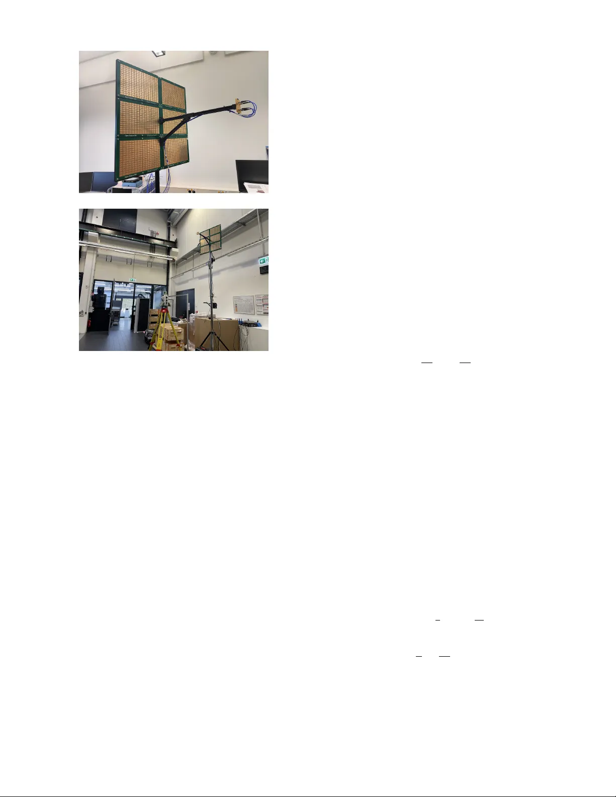
Measurement-Based V alidation of Geometry-Dri v en RIS Beam Steering in Industrial En vironments Adam Umra ⋆ , Simon T ewes ⋆ , Niklas Beckmann † , Niels K ¨ onig † , A ydin Sezgin ⋆ , Robert Schmitt † ⋆ Ruhr Univ ersity Bochum, Germany { adam.umra, simon.tewes, aydin.sezgin } @rub .de † Fraunhofer Institute for Production T echnology , Germany { niklas.beckmann, niels.koenig, robert.schmitt } @ipt.fraunhofer .de Abstract —Reconfigurable intelligent surfaces (RISs) offer pro- grammable control of radio propagation for future wireless sys- tems. F or configuration, geometry-driven analytical approaches are appealing for their simplicity and real-time operation, but their performance in challenging en vironments such as industrial halls with dense multipath and metallic scattering is not well established. T o this end, we present a measurement-based evalu- ation of geometry-driven RIS beam steering in a large industrial hall using a 5 GHz RIS prototype. A novel RIS configuration is proposed in which four patch antennas are mounted in close proximity in front of the RIS to steer the incident field and enable controlled reflection. For this setup, analytically computed, quan- tized configurations are implemented. T wo-dimensional receiv ed power maps from two measurement areas r ev eal consistent, spatially selective focusing. Configurations optimized near the recei ver pr oduce clear power maxima, while steering to offset locations triggers a rapid 20–30 dB reduction. With increasing RIS–recei ver distance, elevation selectivity broadens due to finite- aperture and geometric constraints, while azimuth steering re- mains r obust. These results confirm the practical viability of geometry-driven RIS beam steering in industrial en vironments and support its use f or spatial field control and localization under non-ideal propagation. Index T erms —Reconfigurable intelligent surfaces, industrial wireless communications, beam steering, measurement-based val- idation, beam steering I . I N T RO D U C T I O N Industrial wireless networks are facing increasingly strin- gent performance requirements, dri ven by applications that require ultra-high reliability and very low end-to-end delay with tight latency bounds [1]. In large production halls, radio propagation is strongly shaped by dense multipath, extensi ve metallic infrastructure, and highly reflective surfaces. Care- ful radio planning and site-specific optimization can miti- gate many ef fects in static en vironments, but reconfigurable and matrix manufacturing [2] create dynamic layouts that challenge con ventional planning. In such environments, link characteristics may vary frequently over time, reducing the predictability and long-term ef fecti veness of static beamform- ing and pre-planned wireless configurations [3]. Accordingly , there is growing interest in methods that provide dynamic, en vironment-level control over wireless propagation. This work was supported in part by the German Federal Ministry of Research, T echnology and Space (BMFTR) in the course of the 6GEM+ T ransfer Hub under grant 16KIS2411 and in part by the German Research Foundation (DFG) under Project–ID 287022738 TRR 196 for Project S03. Reconfigurable intelligent surfaces (RISs) have gained trac- tion as a means to shape electromagnetic propagation in future sixth-generation (6G) wireless systems [4], [5]. By enabling programmable control o ver the reflection properties of large surfaces, RISs can improv e coverage, robustness, and energy efficienc y [6], [7], particularly in en vironments that are diffi- cult to influence through con ventional infrastructure. Interest in RIS-assisted systems also e xtends be yond communication to sensing-related applications such as localization, spatial field shaping, and en vironment-aware signal processing [8]–[10]. A central practical requirement is the ability to compute RIS configurations efficiently . In particular , geometry-based analytical channel models are attractive in this context be- cause they provide low-comple xity and real-time-capable op- timization with clear physical interpretability . Howe ver , such models are typically derived under idealizing assumptions (e.g., free-space propag ation, simplified reflection beha vior , incomplete en vironment knowledge). Industrial shop floors are often dominated by non-line-of-sight (NLOS) components, uncontrolled scattering, and dense multipath propagation. In such en vironments, it remains unclear whether configurations deriv ed purely from geometric models can deliver consistent performance in practice. In particular, it is uncertain whether these configurations still provide spatially localized and re- liable control of the receiv ed field once deployed on real hardware. This paper in vestigates this question through a measurement-based study in a representativ e industrial production hall. W e focus on the end-to-end effecti veness of model-driv en, geometry-based RIS beam steering under strongly non-ideal radio propagation. Specifically , we ev aluate whether analytically computed RIS configurations yield spatially selectiv e and repeatable field focusing when deployed directly on a hardware RIS prototype in the presence of sev ere multipath and metallic scattering. A. Related W ork Sev eral experimental studies hav e examined the validity of analytical RIS channel models using hardw are prototypes in controlled indoor en vironments. In [11], a geometry-based RIS channel model is ev aluated in an indoor setting by comparing analytically optimized configurations with measurements, re- vealing deviations attrib utable to hardware impairments and modeling simplifications. Similarly , [12] in vestigates specific model assumptions through measurements in an anechoic chamber , showing that non-perpendicular reflection angles introduce attenuation and phase ef fects that are not captured by ideal free-space models. In contrast to these works, which primarily validate or refine analytical models under controlled indoor propagation con- ditions, the present work assesses the practical effecti veness of geometry-based RIS beam steering in a realistic, large industrial en vironment. The emphasis is on experimentally quantifying spatial controllability and repeatability using mea- sured two-dimensional field distributions. B. Contributions This paper presents a measurement-based assessment of model-driv en RIS beam steering in an industrial production hall. W e conduct an extensi ve measurement campaign using a 5 GHz RIS prototype with binary phase control and a densely discretized spatial measurement grid. W e introduce a ne w transmitter (Tx)–RIS hardware configuration in which four patch antennas are mounted directly in front of the RIS to illuminate the surface and steer the transmitted field to ward it, enabling controlled reflection and wa vefront manipulation for the experiments. For each grid position, RIS configurations are computed from geometry using an analytical method and de- ployed without feedback or en vironment-specific calibration. Based on the resulting two-dimensional received po wer maps, we characterize the degree of spatial field control achie v able with RIS beam steering under realistic industrial radio con- ditions. The results sho w that geometry-based beam steering can produce effecti ve and repeatable spatial focusing despite sev ere multipath and metallic scattering. While increased RIS- to-receiv er distance introduces geometry-induced limitations in ele v ation resolution, rob ust azimuthal steering performance is maintained. These findings support the practical viability of model-driv en RIS optimization in industrial settings and motiv ate its use for localization in future industrial wireless systems. I I . S Y S T E M A N D C H A N N E L M O D E L W e consider a system composed of a single-antenna Tx, a RIS, and a single-antenna recei ver (Rx). The RIS consists of N modules, each equipped with M passi ve reflecting elements (see Fig. 1a), resulting in a total of N M RIS elements. The Tx illuminates the RIS, and the signals reflected by the RIS elements are subsequently receiv ed at the Rx. By properly configuring the phase responses of the RIS elements, the reflected signal components can be coherently combined at the recei ver . Under this assumption, the resulting effecti ve baseband channel between the Tx, RIS and Rx is giv en by h eff = p G T G R N M X m =1 h m θ m g m , (1) where h m ∈ C denotes the channel coef ficient between the transmit antenna and the m -th RIS element, and g m ∈ C represents the channel coef ficient between the m -th RIS el- ement and the recei ver . The terms G T and G R denote the antenna gains at the transmitter and recei ver , respectiv ely . Each RIS element applies a comple x-v alued reflection coefficient θ m = A m ( φ m ) e j φ m , where φ m is the adjustable phase shift and A m ( φ m ) ∈ [0 , 1] models the phase-dependent reflection amplitude. For analytical con venience, we define the cascaded channel corresponding to the m -th RIS element as h casc m = h m g m , (2) which captures the combined propagation effects of the Tx– RIS and RIS–Rx links. T o explicitly characterize these cas- caded channel components, we exploit the geometry of the considered system. Let d h m denote the distance between the transmit antenna and the m -th RIS element, and let d g m denote the distance between the m -th RIS element and the receiv er . According to the free-space propagation model in [13], the individual channel coefficients can be expressed as h m = c 4 π f d h m e j 2 π λ d h m , (3) and g m = c 4 π f d g m e j 2 π λ d g m , (4) where c denotes the speed of light, f is the carrier frequency , and λ is the corresponding wa velength. Consequently , the cascaded channel coefficient associated with the m -th RIS element is giv en by h casc m = c 4 π f d h m e j 2 π λ d h m c 4 π f d g m e j 2 π λ d g m . (5) I I I . E X P E R I M E N TA L V A L I DA T I O N A. Setup An experimental scenario was implemented using a RIS prototype operating in the 5 GHz band. A close-up vie w of the employed RIS is shown in Fig. 1a. Each RIS module has physical dimensions of 360 mm × 247 mm and is described in detail in [14]. In the considered setup, N = 6 RIS modules were mounted on a tripod and arranged in a 3 × 2 planar configuration (see Fig. 1b). The measurements were conducted in a real-world large-scale production en vironment at Fraun- hofer IPT [15] in Aachen, Germany . The corresponding floor plan is depicted in Fig. 2. The factory hall has a length of 97 . 0 m , a width of 28 . 5 m , and an approximate height of 10 m , resulting in a total shop-floor area exceeding 2 , 700 m 2 . The measurements focused on the upper-right re gion of the hall, as highlighted with a red square in Fig. 2. Each RIS module consists of M = 256 unit cells arranged in a 16 × 16 grid. Ev- ery unit cell is equipped with an RF switch that enables phase control. The RIS operates as a binary phase-switching surface, providing a 180 ◦ phase shift at the designed carrier frequency ( 5 . 15 − 5 . 875 GHz ). As illustrated in Fig. 1a, four patch antennas are strategically integrated directly in front of the (a) Close-up view of the Tx & RIS. (b) Tx and RIS mounted on a tripod with the Multi- station positioned in front of the setup. Fig. 1: Overvie w of the experimental setup at the Fraunhofer IPT production hall, including the TX, RIS, and the Leica Multistation. RIS, forming a compact illumination architecture. Rather than relying on a distant feeder , these antennas directly illuminate the surface and independently steer their transmitted signals tow ard the RIS, enabling controlled reflection and wav efront manipulation. Signal transmission was realized using a USRP B200 software-defined radio (SDR) from Ettus Research as the transmitter , while signal reception was carried out with a Signal Hound SM435 spectrum analyzer . On the receiv er side, a standard gain horn antenna was employed to ensure directional reception and suf ficient antenna gain during the measurements. A Leica multistation (surve ying instrument for precise po- sition measurement) was used to survey two distinct areas in front of the RIS as mark ed with bro wn (Area 1) and green (Area 2) shading in Fig. 2. The measurement areas were discretized into a set of grid points. T o demonstrate the ability of the RIS to control the electromagnetic field distrib ution, the RIS configuration was optimized individually for each grid point. A model-based optimization approach based on the previously introduced system model was emplo yed to maxi- mize the received po wer at the selected grid point. The details of the optimization procedure are described in the follo wing subsection. This optimization process w as performed for all grid points in the measurement area. B. Model-based Optimization T o enable real-time optimization of the RIS configurations at each grid point, we employ the channel model described in Section II. As noted previously , the experimental setup uses four patch antennas. For compatibility with the system model, we approximate this antenna array as a single equiv alent antenna, whose location is defined as the geometric center of the four patch antennas. Based on the grid point position, we can generate the current geometry of the system to determine the channels between the grid point and the reflecting elements of the RIS. Thus, giv en the channel values, we are able to compute a beam to this grid point and round the values to the closest possible switch state. Giv en the absence of a direct link between Tx and Rx, we account for various phase v alues in the effecti ve channel to optimize the RIS state for achieving the most efficient configuration. In order to guarantee real-time capability , we compute the RIS configuration analytically , expressed as φ ∗ m ( ϑ t ) = ϑ t − φ ′ m , (6) where ϑ t denotes an arbitrary value for the desired phase at the recei ver , due to the absence of a direct Tx-Rx link. Accordingly , the cascaded channel phase φ ′ m is giv en by φ ′ m = 2 π λ d h m + 2 π λ d g m . (7) Although the flexibility in selecting ϑ t allows us to iterate through any number of e venly-distrib uted phase values ϑ t , we reduce the maximum number of allowed values to T = 4 . This achiev es a balanced tradeoff between the quality of the RIS-enabled link and the time needed in order to determine the optimal configuration. After determining the analytical solution for the T phase values, we round the continuous phase shifts at each reflecting element to the nearest possible binary switching state of the RIS prototype. For these prototype- deployable RIS configurations, we choose the best performing one by assessing and comparing the simulated performances of the resulting RIS-facilitated links. This process can be represented mathematically as h eff t = N M X m =1 h casc m A m ( rd ( φ ∗ m ( ϑ t ))) e j rd ( φ ∗ m ( ϑ t )) , ∀ ϑ t ∈ Θ , (8) with A m ( τ ) = ( 0 . 5012( − 3 dB ) , if τ = π 1 , otherwise , (9) rd ( τ ) = ( π , if π 2 ≤ τ < 3 π 2 0 , otherwise , (10) Θ = 0 , π 2 , π , 3 π 2 , | Θ | = T , (11) where an additional attenuation of 3dB to the reflected path of reflecting element m is assumed, if it is activ e. This attenuation is considered in the simulations in order to capture the hardware limitations of the utilized RIS prototype [14]. Flo or Plan Measuremen t Area Measuremen t Area Measuremen t Area Measuremen t Area Measuremen t Area Measuremen t Area Measuremen t Area Measuremen t Area Measuremen t Area Measuremen t Area Measuremen t Area Measuremen t Area Measuremen t Area Measuremen t Area Measuremen t Area Measuremen t Area Measuremen t Area Area 1 Area 1 Area 1 Area 1 Area 1 Area 1 Area 1 Area 1 Area 1 Area 1 Area 1 Area 1 Area 1 Area 1 Area 1 Area 1 Area 1 RIS RIS RIS RIS RIS RIS RIS RIS RIS RIS RIS RIS RIS RIS RIS RIS RIS Area 2 Area 1 Area 2 Area 2 Area 2 Area 2 Area 2 Area 2 Area 2 Area 2 Area 2 Area 2 Area 2 Area 2 Area 2 Area 2 Area 2 Area 2 Area 2 97 m 28 m Fig. 2: Floor plan of the production hall at Fraunhofer IPT in Aachen. The area where measurements were conducted is highlighted by a red square. The considered areas are marked with green and brown shading, and the RIS position is marked with a blue rectangle. I V . E X P E R I M E N TA L R E S U L T S This section presents and analyzes the results obtained from the experimental measurement campaign described in Section III. The objective of the measurements is to ex- perimentally validate the ability of the RIS to shape and control the spatial distribution of the receiv ed signal power within the predefined measurement areas using the model- based optimization strategy introduced in the pre vious section. For each grid point (i.e., measured spatial position) recorded with the Leica Multistation, the corresponding RIS configu- ration was computed analytically using the geometry-based channel model and subsequently implemented on the RIS prototype. Throughout this procedure, the receiv er position was kept fixed, while the RIS configuration was updated individually for each grid point. The complete measurement campaign was conducted in both areas and, within each area, for two distinct receiver locations: one placed relativ ely close to the RIS and another at a lar ger distance. This setup enables a systematic in vestigation of geometric effects on the achie vable spatial focusing performance. All measurements were conducted at a carrier frequency of 5 . 375 GHz . The RIS was mounted on a tripod at a height of 3 . 6 m above the ground, and the Tx–RIS distance was fixed to 0 . 587 m . The RIS position and orientation were kept constant across all measurements, as shown in Fig. 1b and Fig. 2. For each optimized RIS configuration, the received signal power was measured using the spectrum analyzer . The Rx antenna was positioned at a height of 1 . 1 m . The resulting heat maps visualize the measured receiv ed power over the spatial grid. T o aid visualization, the maps are obtained by interpolating the measured values across the grid. The native spacing (resolution) of the underlying grid points was 10 cm. Since the RIS height and the receiv er height are fixed, variations along the grid direction pointing away from the RIS correspond predominantly to changes in the elev ation angle, whereas variations along the lateral grid direction correspond predominantly to changes in the azimuth angle. A. Ar ea 1 This subsection analyzes the measured spatial distribution of the receiv ed signal power in Area 1 for two receiver positions relative to the RIS, as shown in Fig. 3. Fig. 3a depicts the measured receiv ed power distribution for receiv er position 1, which is located in close proximity to the RIS. The resulting heat map shows a pronounced peak in receiv ed power for RIS configurations optimized for grid points near the true receiver position (approximately − 50 dBm ). As the spatial offset between the optimized grid point and the recei ver increases, the receiv ed po wer drops rapidly by about 20 – 30 dB . This behavior indicates that the analytically deri ved RIS configurations effecti vely steer and focus the reflected wa vefront toward the intended spatial locations. In addition, the narrow high-power region demonstrates a high degree of spatial selectivity in both grid directions (i.e., primarily azimuth and ele v ation-angle selectivity), confirming that for short RIS-to-receiv er distances a tightly focused reflection pattern can be achieved in a highly reflectiv e industrial en- vironment. The measured received power distribution for recei ver posi- tion 2 is shown in Fig. 3b. Here, the recei ver is placed farther from the RIS, while the same grid-based optimization proce- dure is applied. Compared to position 1, the high-power re gion becomes noticeably broader , and the peak receiv ed po wer decreases to about − 55 dBm , consistent with the increased RIS–receiv er distance. Elev ated received po wer is observed not only for RIS configurations optimized for grid points near the receiver location, but also for configurations targeting grid points closer to the RIS. This suggests a larger spread of the reflected ener gy in the elev ation dimension, which can be attributed to propagation geometry and the finite aperture of the RIS. Ne vertheless, azimuthal steering remains effecti ve despite the increased RIS-to-receiv er distance. B. Ar ea 2 This subsection examines the measured spatial distribution of the receiv ed power in Area 2 for two recei ver locations relativ e to the RIS. In contrast to Area 1, Area 2 features x-co ordina te [m] -40 -35 -30 -25 -20 -15 -10 -5 0 y-c o ordinate [m ] -15 -10 -5 0 5 10 -100 -95 -90 -85 -80 -75 -70 -65 -60 -55 -50 Received Po wer [dBm] Ground T ruth RIS (a) Rx position 1 (near RIS). x-co ordina te [m] -40 -35 -30 -25 -20 -15 -10 -5 0 y-c o ordinate [m ] -15 -10 -5 0 5 10 -100 -95 -90 -85 -80 -75 -70 -65 -60 -55 -50 Received Po wer [dBm] Ground T ruth RIS (b) Rx position 2 (far from RIS). Fig. 3: Area 1: measured recei ved power (dBm) heat maps for two receiv er positions (near and far), using geometry-based per-grid-point RIS optimization. a more constrained, corridor-lik e geometry . Therefore, the analysis focuses primarily on steering behavior along the grid direction that mainly corresponds to v ariations in elev ation angle. Figure 4a shows the measured received power distribution for recei ver position 1, located close to the RIS. The heat map exhibits a clear localization of receiv ed power around the grid points corresponding to the true receiver location, with a peak le vel of approximately − 50 dBm . As the spatial offset between the optimized grid point and the actual receiv er position increases, the recei ved power decays rapidly by 20 – 30 dB . This observation is consistent with the behavior in Area 1 and confirms that, at short RIS-to-receiver distances, the analytically computed configurations produce a tightly focused reflection pattern that closely follows the intended grid-point targets. The receiv ed power distribution for receiv er position 2 is presented in Fig. 4b. Here, the receiv er is located farther from the RIS, leading to a reduced peak received power of about − 55 dBm and a noticeably broader high-power region, particularly along the grid direction associated with ele v ation- angle variations. Elev ated receiv ed power occurs not only for configurations optimized for grid points near the receiv er , but also for configurations targeting points closer to the RIS. This indicates increased spreading of the reflected wavefront, which can be attributed to propagation geometry and the limited effecti ve aperture of the RIS at larger distances. x-co ordina te [m] -40 -35 -30 -25 -20 -15 -10 -5 0 y-c o ordinate [m ] -15 -10 -5 0 5 10 -100 -95 -90 -85 -80 -75 -70 -65 -60 -55 -50 Received Po wer [dBm] Ground T ruth RIS (a) Rx position 1 (near RIS). x-co ordina te [m] -40 -35 -30 -25 -20 -15 -10 -5 0 y-c o ordinate [m ] -15 -10 -5 0 5 10 -100 -95 -90 -85 -80 -75 -70 -65 -60 -55 -50 Received Po wer [dBm] Ground T ruth RIS (b) Rx position 2 (far from RIS). Fig. 4: Area 2: measured recei ved power (dBm) heat maps for two receiv er positions (near and far), using geometry-based per-grid-point RIS optimization. C. Discussion The measurements show that RIS configurations computed from a geometry-based model can impose a structured and spatially selective receiv ed-power distribution in a large indus- trial hall. In both measurement areas, configurations optimized near the true receiver position yield a clear power maximum, while targeting offset grid points produces a rapid power reduction by 20–30 dB. This indicates that geometric steer- ing remains ef fecti ve despite strong multipath and metallic scattering. The observed patterns deviate from an ideal focus. Peak broadening and reduced contrast are consistent with practical non-idealities of the setup, including binary phase control, finite effecti ve aperture, finite grid resolution, and residual model mismatch. A consistent trend is that increasing the RIS–receiv er distance reduces selectivity along the grid direction associated with elev ation-angle variations, whereas azimuthal steering remains comparatively robust; this aligns with aperture- and geometry-driven angular compression at larger ranges and the effect of phase discretization. T aken together , the results suggest that geometry-driven configuration can provide spatial structure that is stable enough to be informativ e beyond pure power maximization. In par- ticular , the strong contrast between configurations targeting nearby versus displaced grid points implies location-dependent signatures that could be exploited for coarse localization, e.g., by matching measured power responses to a precomputed map or by using power gradients to refine candidate positions. Establishing this link rigorously will require quantifying reso- lution and repeatability over time and across deployments, and ev aluating localization performance under realistic dynamics. V . C O N C L U S I O N This paper presented a measurement-based validation of geometry-driv en RIS beam steering in a large-scale industrial production hall characterized by strong multipath propagation and metallic scattering. A RIS prototype was illuminated by four patch antennas mounted directly in front of the surface. Using analytically derived phase configurations, spatially se- lectiv e and repeatable beam steering was demonstrated. This was achieved without relying on measurement feedback or en vironment-specific model refinement. The measured field distributions closely follow the intended geometric targeting, confirming the practical applicability of model-based RIS opti- mization under realistic industrial conditions. While increasing the RIS–receiv er distance leads to reduced elev ation resolution due to fundamental geometric and aperture limitations, robust azimuthal steering performance is preserved. These results highlight the suitability of RIS-assisted systems for industrial localization tasks and support their integration into future industrial wireless networks. R E F E R E N C E S [1] M. Luvisotto, Z. Pang, and D. Dzung, “High-performance wireless networks for industrial control applications: New targets and feasibility , ” Pr oc. IEEE , vol. 107, no. 6, pp. 1074–1093, 2019. [2] J. Mohr , N. Schmidtke, and F . Behrendt, “Design of matrix produc- tion systems: New demands on factory planning methods, ” Pr ocedia Computer Science, P art of special issue: 5th ISM 2023 , vol. 232, pp. 1972–1981, 2024. [3] M. Noor-A-Rahim, J. John, F . Firyaguna, H. H. R. Sherazi, S. Kushch, A. V ijayan, E. O’Connell, D. Pesch, B. O’Flynn, W . O’Brien, M. Hayes, and E. Armstrong, “W ireless communications for smart manufacturing and industrial IoT: Existing technologies, 5G and beyond, ” Sensors , vol. 23, no. 1, 2023. [4] E. Basar , M. Di Renzo, J. De Rosny , M. Debbah, M.-S. Alouini, and R. Zhang, “W ireless communications through reconfigurable intelligent surfaces, ” IEEE Access , vol. 7, pp. 116 753–116 773, 2019. [5] M. Di Renzo, A. Zappone, M. Debbah, M.-S. Alouini, C. Y uen, J. de Rosny , and S. T retyakov , “Smart radio environments empowered by reconfigurable intelligent surfaces: Ho w it works, state of research, and the road ahead, ” IEEE J. Sel. Areas Commun. , vol. 38, no. 11, pp. 2450–2525, 2020. [6] Q. Wu and R. Zhang, “T owards smart and reconfigurable environment: Intelligent reflecting surface aided wireless network, ” IEEE Commun. Mag. , vol. 58, no. 1, pp. 106–112, 2020. [7] K. W einberger , A. A. Ahmad, A. Sezgin, and A. Zappone, “Synergistic benefits in IRS- and RS-enabled C-RAN with ener gy-efficient cluster- ing, ” IEEE T rans. Wir el. Commun. , vol. 21, no. 10, pp. 8459–8475, 2022. [8] A. Magbool, V . Kumar , Q. W u, M. Di Renzo, and M. F . Flanagan, “ A survey on integrated sensing and communication with intelligent metasurfaces: Trends, challenges, and opportunities, ” IEEE Open J. Commun. Soc. , vol. 6, pp. 7270–7318, 2025. [9] K. W einberger , S. T ewes, and A. Sezgin, “Show me the way: Real-time tracking of wireless mobile users with UWB-enabled RIS, ” in Proc. 19th ISWCS , 2024, pp. 1–6. [10] A. Umra, A. M. Ahmed, S. Roth, and A. Sezgin, “Hardware-ef ficient cognitiv e radar: Multi-target detection with RL-driven transmissi ve RIS, ” 2025. [Online]. A vailable: https://arxiv .org/abs/2509.14160 [11] K. W einberger , S. T ewes, M. Heinrichs, R. Kronberger , and A. Sezgin, “RIS-based channel modeling and prototypical v alidation, ” in Pr oc. WSA & SCC , 2023, pp. 1–6. [12] K. W einberger , S. T ewes, and A. Sezgin, “V alidating properties of ris channel models with prototypical measurements, ” in Proc. 18th EuCAP , 2024, pp. 1–5. [13] A. Goldsmith, W ir eless Communications . Cambridge Uni versity Press, 2005. [14] M. Heinrichs, A. Sezgin, and R. Kronberger , “Open source reconfig- urable intelligent surface for the frequency range of 5 GHz WiFi, ” in Pr oc. ISAP , 2023, pp. 1–2. [15] Fraunhofer Institute for Production T echnol- ogy (IPT), “5G-industry campus europe, ” https://www .ipt.fraunhofer .de/de/profil/hallenrundgang.html, n.d., online; accessed 13 January 2026.
Original Paper
Loading high-quality paper...
Comments & Academic Discussion
Loading comments...
Leave a Comment