Waveform Design for ISAC System: A Consensus ADMM Approach
We study joint transmit-waveform and receive-filter design for a multi-user downlink integrated sensing and communication (ISAC) system under practical constant-modulus and similarity constraints. We cast the design as a unified multi-objective progr…
Authors: Ngoc-Son Duong, Huyen-Trang Ta, Quang-Tang Ngo
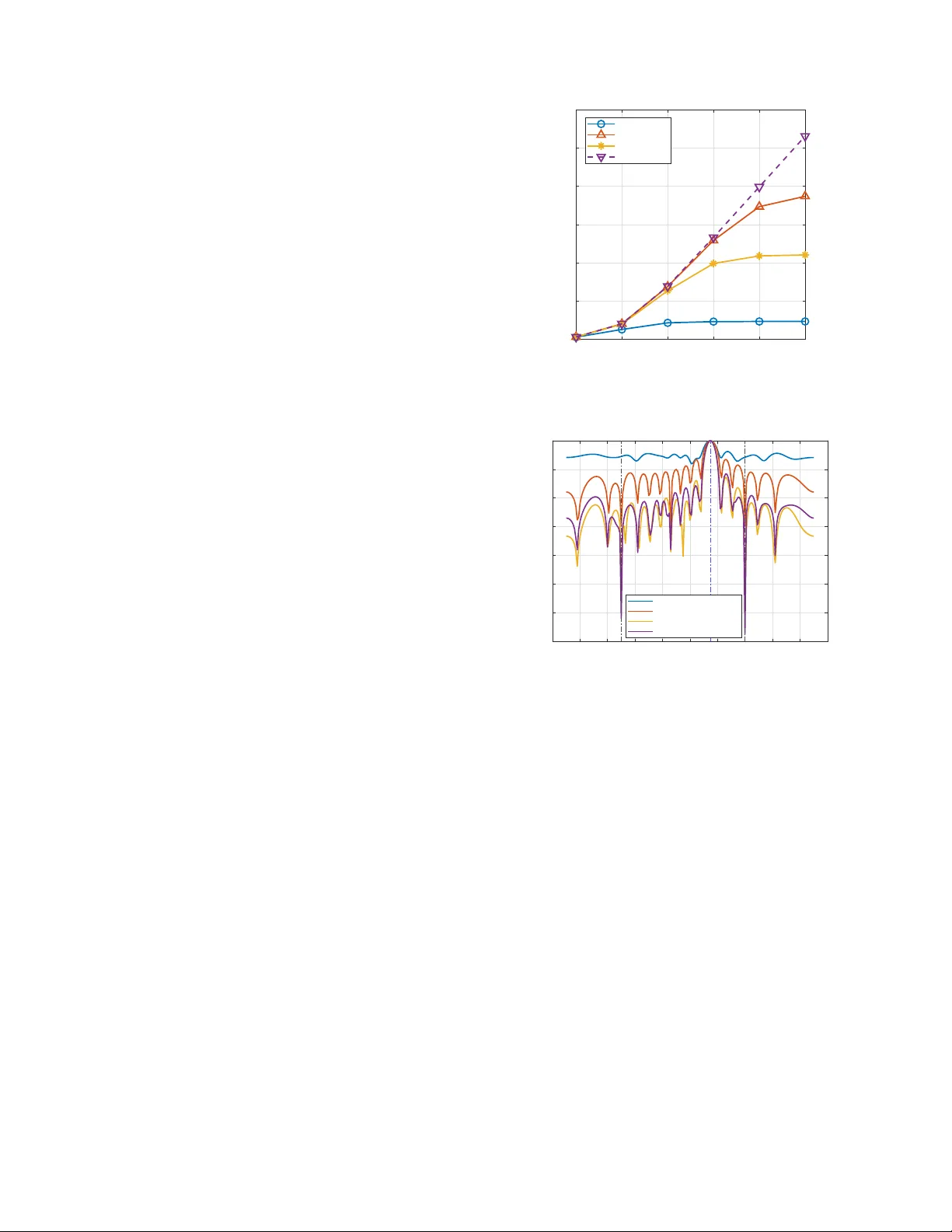
W a v eform Design for ISA C System: A Consensus ADMM Approach Ngoc-Son Duong ∗ , Huyen-T rang T a ∗ , Quang-T ang Ngo ∗ , Thi-Hue Duong ∗ , V an-Lap Nguyen ∗ , Cong-Minh Nguyen † , Nguyen Minh T ran ∗ , and Thai-Mai Dinh # ∗ ∗ Faculty of Electronics and T elecommunications, VNU Uni versity of Engineering and T echnology , Hanoi, V ietnam † National Foundation for Science and T echnology De velopment, Hanoi, V ietnam E-mails: { sondn24, 22029064, 22029037, 22029040, 23020619, minhtran.nguyen, dttmai } @vnu.edu.vn, ncminh1805@gmail.com. ( # Corr esponding A uthor ) Abstract —W e study joint transmit-wa veform and receive-filter design for a multi-user do wnlink integrated sensing and com- munication (ISA C) system under practical constant-modulus and similarity constraints. W e cast the design as a unified multi- objective pr ogram that balances communication sum rate and sensing signal-to-interference-plus-noise ratio (SINR). T o address this, we introduce an efficient algorithm that use consensus alternating direction method of multipliers (ADMM) framework to alternately update the transmit wavef orm and radar filter . The proposed method effectively handles the non-con vex fractional sensing’ s SINR formulation and ensures fast conv ergence. Simu- lation results demonstrate that the proposed approach achiev es better trade-offs between communication sum rate and sensing’ s SINR compared to existing benchmark schemes. Index T erms —6G, integrated sensing and communication, wav eform design, consensus ADMM. I . I N T RO D U C T I O N The concept of integrated sensing and communication (ISA C) has emer ged as a transformativ e approach for next- generation wireless systems, particularly in the context of 5G and beyond. ISAC systems enable the simultaneous use of the same w aveform for both radar sensing and communication, offering significant advantages in terms of spectrum ef ficiency , latency reduction, and system resource sharing. By incorporat- ing sensing and communication into a unified frame work, ISA C holds the potential to significantly enhance the performance of next generation wireless systems, especially in applications like Internet of Things (IoT) and intelligence transportation systems. Howe ver , optimizing performance in ISAC systems remains a big challenge due to the dual nature of the tasks in volv ed. Both radar sensing and communication tasks hav e distinct requirements, such as the need for high sensitivity in radar target detection and robust signal reception for communi- cation systems. Thus, designing a transmit wa veform that meets both these objectiv es while managing interference and resource constraints is nontrivial. One of the primary challenges in ISA C design is waveform optimization, where the transmitted wa veform must satisfy both radar sensing and communication This work has been done under the research project QG.25.06 “ A Novel Algorithm for Joint Sensing and Communications in Next Generation Mobile Networks” of V ietnam National University , Hanoi. Ngoc-Son Duong is now with Faculty of Electronic Engineering, Posts and T elecommunications Institute of T echnology , Hanoi, V ietnam, email: sondn@ptit.edu.vn objectiv es. In radar systems, this in volves optimizing the wa ve- form for tar get detection, while in communication systems, the focus shifts to efficient data transmission. Striking the right balance between these competing goals requires advanced techniques for managing the shared resources. Recent advancements in ISA C have been demonstrated across multiple studies. In particular , [1] introduces a penalty- based iterati ve beamformer optimization using block coor- dinate descent and weighted minimum mean square error for a full-duplex monostatic ISA C system, achieving up to 60 dB self-interference cancellation and significant improv e- ments in both radar and communication performance. Follo w- ing this direction, two cross-domain wa veform optimization strategies—communication-centric and sensing-centric—are presented in [3], jointly optimizing time, frequency , power , and delay-Doppler domains to suppress sidelobes, reduce peak-to- av erage power ratio (P APR), and enhance both sensing accu- racy and communication efficienc y . Meanwhile, a hardware- efficient massi ve multiple-input multiple-output (MIMO) ISA C framew ork is dev eloped in [2], employing quantized constant- en velope constraints and lo w-resolution digital-to-analog con- verters, where an inexact augmented Lagrangian method with block successive upper -bound minimization effecti vely reduces beampattern mean squared error (MSE) and symbol error rate, highlighting the potential of massiv e MIMO for future radar performance enhancement. In addition, [4] proposes two wave- form designs—DSSS and OFDM—where DSSS with pseudo- random coding offers simplicity but suffers from Doppler and low data rates, whereas OFDM symbol-domain processing mitigates interference, accurately estimates multi-target range and velocity , and supports high-speed communication. T o fur- ther enhance ISA C performance, [5] explores the integration of reconfigurable intelligent surface (RIS), jointly optimizing beamforming and RIS phase configuration to impro ve both target illumination power and user SINR, thereby maintaining effecti ve operation even when the direct path is degraded or blocked. Finally , when the direct transmission path is obstructed, [6] demonstrates that coordinated optimization of beamforming and RIS phase for both radar and communica- tion continues to enhance user signal-to-interference-plus-noise ratio (SINR) and radar target illumination, ensuring reliable Channel Estimation And Radar Wavefo rm Design Joint Optimization Under Constraints ISAC System ′ s T ransmitter ISAC System ′ s Receiver Linear Filter Hypothesis T est S , H θ 0 , θ 1 , . . . , θ K σ 2 1 , σ 2 2 , . . . , σ 2 K σ 2 u X w w H q R T X , w q T arget Source Interference Source 1 Interference Source K UT 1 UT M y 1 y M Decision False Alarm Probability Fig. 1. The ISAC system model with operation flow-chart. dual-function performance e ven without a direct link. In this paper , we present a novel wav eform design frame- work for ISA C systems that jointly optimizes radar sensing and communication performance under practical hardware con- straints using consensus alternating direction method of multi- pliers (ADMM) [9]. The designed wa veform problem is formu- lated as a multi-objectiv e optimization task that balances target detection capability and communication efficienc y . T o address its non-conv ex nature, a novel algorithm based on consensus ADMM is dev eloped, enabling alternating optimization of the transmit wav eform and receiv e filter while enforcing constant- modulus (CM) and similarity constraints. Simulation results verify that the proposed method achieves better trade-offs between radar and communication performance, demonstrating its practicality , scalability , and effecti veness for ne xt-generation ISA C implementations. I I . S Y S T E M M O D E L Fig. 1 illustrates the overall architecture of a ISA C system in which the transmitter is equipped with a uniform linear array (ULA) of T elements. The system simultaneously supports downlink communication to M single-antenna user equipments (UE) and transmits radar probing wav eforms to detect point- like targets. In addition, it is assumed that the ISA C system includes a dedicated receiv e ULA with R elements, following the model of a radar system with collocated transmit and receiv e antenna arrays. W e will provide a detailed presentation of the communication and radar functionalities in the follo wing subsections. A. Communication model The signal matrix recei ved at the communication user over the N symbol interv als is e xpressed as Y = HX + Z , (1) where Y ∈ C M × N is the received signal matrix, and y m,n de- notes the signal recei ved at the m -th UE during the n -th symbol period. The transmit matrix X = [ x 1 , . . . , x N ] ∈ X ⊂ C T × N consists of transmit v ectors x n ∈ C T × 1 , where X defines the feasible set with spatial and temporal constraints. The channel matrix H = [ h 1 , . . . , h M ] T ∈ C M × T models a flat- fading MIMO link, with each Gaussian random vector h m ∼ C N (0 , I T ) . The noise matrix Z = [ z 1 , . . . , z N ] ∈ C M × N rep- resents additiv e white Gaussian noise (A WGN) at the receiv ers, where noise vector z n ∼ C N (0 , σ 2 z I M ) and σ 2 z denotes the noise power . Let s m,n ∈ O denote the data symbol, which are drawn from a finite constellation O . The desired symbol vector is represented as s n = [ s 1 ,n , ..., s M ,n ] ⊤ ∈ O M × 1 , and the entire symbol matrix is denoted as S = [ s 1 , ..., s N ] ∈ C M × N . The communication objective is to design transmit vectors x n such that the receiv ed signals y n = Hx n + z n approximate the desired symbol vectors s n as closely as possible. This can be formulated as the minimization of the total Multi-user Interference (MUI) ener gy f ( X ) = ∥ HX − S ∥ 2 F , (2) where ∥ · ∥ F denotes the Frobenius norm. B. Radar model Let us consider the transmit signal vector x n ∈ C T × 1 at the n -th symbol time, where 1 ≤ n ≤ N , emitted by the ISA C system. The signal received at a location with azimuth angle θ is giv en by a ⊤ t ( θ ) x n , x ∈ N , where a t ( θ ) ∈ C T × 1 denotes the transmit steering vector . Under the ULA configuration, a t ( θ ) takes the form a t ( θ ) = 1 √ T [1 , e − j π sin( θ ) , . . . , e − j π ( T − 1) sin( θ ) ] ⊤ . (3) Assume that a target is located at angle θ 0 and there are K interference sources located at angles θ k , k ∈ [ K ] . The recei ved baseband signal vector q n ∈ C R × 1 at the n -th symbol time is giv en by q n = α 0 a r ( θ 0 ) a ⊤ t ( θ 0 ) x n + K X k =1 α k a r ( θ k ) a ⊤ t ( θ k ) x n + u n , (4) where α 0 , α k are complex gains of the target ( E {| α 0 | 2 } = σ 2 0 ) and the k -th interference source ( E {| α k | 2 } = σ 2 k ), respectively . The noise vector u n ∼ C N (0 , σ 2 u I R ) is modeled as spatially white circular Gaussian noise. The receive steering vector a r ( θ ) ∈ C R × 1 is defined analogously as a r ( θ ) = 1 √ R [1 , e − j π sin( θ ) , . . . , e − j π ( R − 1) sin( θ ) ] ⊤ . (5) Assuming that the angle of departure and arri val are identical (i.e., transmit and receive arrays are collocated), the receiv ed signal q can be re written as q = A ( θ 0 ) x + K X k =1 A ( θ k ) x + u , (6) where A ( θ ) = I N ⊗ [ a r ( θ ) a ⊤ t ( θ )] . (7) A finite impulse response filter w ∈ C R × 1 is applied to the receiv ed signal q to form c = w H q = α 0 w H A ( θ 0 ) x + K X k =1 α k w H A ( θ k ) x + w H u . (8) The output sensing’ s SINR is expressed as SINR ( x , w ) = σ 2 0 | w H A ( θ 0 ) x | 2 P K k =1 σ 2 k | w H A ( θ k ) x | 2 + σ 2 u ∥ w ∥ 2 . (9) Intuitiv ely , the waveform x and the receiv e filter w can thus be jointly designed by maximizing SINR ( x , w ) . This maximization ensures enhanced target detection probability , while placing deep nulls in the directions of known interference sources. The beamforming effect arises naturally from this joint design, eliminating the need for predefined look directions. When en vironmental aw areness is av ailable, such as prior in- formation on interference angles and powers, the optimization can be further improved via cognitive radar techniques. I I I . P RO B L E M F O R M U L A T I O N A N D P RO P O S E D M E T H O D A. Pr oblem F ormulation The formulation simultaneously aims to minimize commu- nication distortion, captured by a distortion metric f ′ ( x ) = ∥ ˜ Hx − s ∥ 2 2 , where ˜ H = H ⊗ I , x = vec ( X ) and s = vec ( S ) ; to maximize radar sensing performance, quantified via the output SINR SINR ( x , w ) ; and to promote structural similarity between the synthesized and reference radar waveform x 0 . The resulting optimization problem is formulated as min x , w ρf ′ ( x ) + (1 − ρ ) 1 SINR ( x , w ) + (1 − ρ ) λ ∥ x − x 0 ∥ 2 2 s.t. | x n | = r P max T N , ∀ n (10) where P max denotes total transmission power and the parame- ter ρ ∈ [0 , 1] controls the trade-off between communication and sensing objectiv es. Meanwhile, the trade-of f is further modulated by a regularization parameter λ > 0 , which controls the emphasis placed on waveform similarity relative to other objectiv es. This soft constraint provides flexibility and enables compatibility with multi-objecti ve waveform design formula- tions. B. Pr oposed method As all the problems are nonconv ex but have differentiable objectiv e functions with respect to both w and x , we adopt the alternating minimization frame work. The steps are giv en by x ( k +1) = arg min x g ( x , w ( k ) ) , (11) w ( k +1) = arg min w (1 − ρ ) 1 SINR ( x ( k +1) , w ) , (12) where x ( k ) and w ( k ) are the solutions av ailable to problems (11) and (12), respectiv ely , at the k -th iteration. Besides, g ( x , w ( k ) ) is e xact (10) with kno wn w . C. Optimize w when knowing x Let | w H A ( θ 0 ) x | = 1 , the closed-form solution of w is gi ven by [10] w = B − 1 a a H B − 1 a , (13) where B = P K k =1 σ 2 k A ( θ k ) x A ( θ k ) x H + σ 2 u I and a = A ( θ 0 ) x . D. Optimize x when knowing w Introduce (w .r .t. w ) R t ≜ σ 2 0 A ( θ 0 ) H ww H A ( θ 0 ) , R i ≜ P K k =1 σ 2 k A ( θ k ) H ww H A ( θ k ) so that SINR ( x , w ) = x H R t x x H R i x + σ 2 u ∥ w ∥ 2 2 . It is easy to see that minimizing 1 /γ is equiv alent to minimizing x H R i x subject to x H R t x = σ 2 0 ; howe ver , the CM constraint pre vents a direct solution. W e, therefore, split the objective into three blocks by introducing consensus copies x c , x s , x b for the communication term, sens- ing term, and similarity term, respectiv ely . The problem (10) is re-written as min ρ ∥ ˜ Hx c − s ∥ 2 2 + (1 − ρ ) x H s R i x s + (1 − ρ ) λ ∥ x b − x 0 ∥ 2 2 s.t. x c = x , x s = x , x b = x x H s R t x s = σ 2 0 | x n | = c, ∀ n (14) Ignore the last two constraints, the augmented Lagrangian corresponding is gi ven by L ρ ( x c , x s , x b , µ , x ) = ρ ( ˜ Hx c − s ) + µ H c ( x c − x ) + γ 2 ∥ x c − x ∥ 2 2 +(1 − ρ ) x H s R i x s + µ H s ( x s − x ) + γ 2 ∥ x s − x ∥ 2 2 +(1 − ρ ) λ ∥ x b − x 0 ∥ 2 2 + µ H b ( x b − x ) + γ 2 ∥ x b − x ∥ 2 2 (15) The resulting iterations are gi ven by x ( t +1) c = arg min x c { ρ ( ˜ Hx c − s ) + µ H c ( t ) x c − x ( t ) + γ 2 ∥ x c − x ( t ) ∥ 2 2 } . (16) x ( t +1) s = arg min x s { (1 − ρ ) x H s R i x s + µ H s ( t ) x s − x ( t ) + γ 2 ∥ x s − x ( t ) ∥ 2 2 } s.t. x H s R t x s = σ 2 0 (17) x ( t +1) b = arg min x b { (1 − ρ ) λ ∥ x b − x 0 ∥ 2 2 + µ H b ( t ) x b − x ( t ) + γ 2 ∥ x b − x ( t ) ∥ 2 2 } . (18) x ( t +1) = arg min x N X i =1 n µ H i ( t ) ( − x ) + γ 2 ∥ x ( t +1) i − x ∥ 2 2 o . (19) µ ( t +1) i = µ ( t ) i + γ x ( t +1) i − x ( t +1) , i ∈ { c, s, b } (20) 1) Solution for (16) : W e, herein, use the scaled ADMM [11] to solv e it. Let u ( t ) c = 1 γ µ ( t ) c , (16) can be re-written as x ( t +1) c = arg min x c ∥ ˜ Hx c − s ∥ 2 2 + γ 2 ∥ x c − x ( t ) + u ( t ) c ∥ 2 2 . (21) T o find x c , we deri ve the deri vati ve of right hand side (RHS) of (21) with respect to x c and set it to 0 ˜ H H ( ˜ Hx c − s ) + γ 2 ( x c − x ( t ) + u ( t ) c ) = 0 . (22) Then, we get x ( t +1) c = ˜ H H ˜ H + γ 2 I − 1 ˜ H H s + γ 2 x ( t ) − γ 2 u ( t ) c . (23) 2) Solution for (17) : The equality constraint makes problem (17) non-conv ex. Solving it directly is not easy and so we relax the equality constraint with an inequality , as follo ws x ( t +1) s = arg min x s { (1 − ρ ) x H s R i x s + µ H s ( t ) x s − x ( t ) + γ 2 ∥ x s − x ( t ) ∥ 2 2 } s.t. x H s R t x s ≤ σ 2 0 . (24) This problems is classifed as quadratically constrained quadratic program (QCQP). Let u ( t ) s = 1 γ µ ( t ) s , we ha ve x ( t +1) s = arg min x s { (1 − ρ ) x H s R i x s + γ 2 ∥ x s − x ( t ) + u ( t ) s ∥ 2 2 } s.t. x H s R t x s ≤ σ 2 0 (25) The Lagrangian of the QCQP problem in the first place can be written as L ( x s , τ ) = (1 − ρ ) x H s R i x s + γ 2 x s − x ( t ) + u ( t ) s 2 2 + τ x H s R t x s − σ 2 0 . (26) The KTT condition for this problem is R i x s + γ 2 ( x s − x ( t ) + u ( t ) s ) + τ R t x s = 0 , (27) equiv alently ( R i + γ 2 I + τ R t ) x s = γ 2 ( x ( t ) − u ( t ) s ) (28) with primal feasibility x H s R t x s ≤ σ 2 0 , dual feasibility τ ≥ 0 and complementary slackness τ ( x H s R t x s − σ 2 0 ) = 0 . Herein, we see that if τ = 0 , the solution is x s = ( R i + γ 2 I ) − 1 ( γ 2 ( x ( t ) − u ( t ) s )) . (29) W e then check x s for primal feasibility , if it is satisfied, we stop. Else, there exists a τ > 0 such that ( x s = ( R i + γ 2 I + τ R t ) − 1 ( γ 2 ( x ( t ) − u ( t ) s )) x s ( τ ) H R t x s ( τ ) = σ 2 0 (30) Let q ( τ ) = x s ( τ ) H R t x s ( τ ) , then q ( τ ) is strictly decreasing in τ , hence the equation q ( τ ) = σ 2 0 has a unique solution τ ⋆ > 0 . In this case, one can use Bi-section search [12] to find τ ⋆ . 3) Solution for (18) : Let u ( t ) b = 1 γ µ ( t ) b , we ha ve x ( t +1) b = arg min x b (1 − ρ ) λ ∥ x b − x 0 ∥ 2 2 + γ 2 ∥ x b − x ( t ) + u ( t ) b ∥ 2 2 . (31) T o find x b , we deri ve the deri vati ve of RHS of (31) with respect to x b and set it to 0 (1 − ρ ) λ ( x b − x 0 ) + γ 2 ( x b − x ( t ) + u ( t ) b ) = 0 . (32) Then, we get x ( t +1) b = (1 − ρ ) λ x 0 + γ 2 x ( t ) − u ( t ) b (1 − ρ ) λ + γ 2 (33) 4) Solution for (19) : Let m = 3 be the number of local blocks, the consensus step solv es a least-squares average x ( t +1) = 1 m X i ∈{ c,s,b } x ( t +1) i + u ( t ) i . (34) Finally , we project x ( t +1) onto the CM set as [13] x ( t +1) n = q P max T N , x n = 0 q P max T N x ( t +1) n | x ( t +1) n | , x n = 0 . (35) Algorithm 1: Proposed consensus ADMM for finding x given w Input: ˜ H , s , R i , R t , x 0 , λ , ρ ∈ [0 , 1) , γ > 0 , ADMM tolerances ( ε p , ε d ) Output: x ⋆ Initialize: x (0) ; u (0) c = u (0) s = u (0) b = 0 , t ← 0 . while 1 do 1) Local updates: - Update x ( t +1) c via (23); - Update x ( t +1) s via (29) or via solving (30); - Update x ( t +1) b via (33); 2) Global consensus update: Update x ( t +1) via (34); 3) Projection: - Update x ( t +1) n via (35); 4) Dual update: u ( t +1) i = u ( t ) i + x ( t +1) i − x ( t +1) , ∀ i ∈ { c, s, b } ; 5) ADMM stopping check: r ( t +1) ← ∥ x ( t +1) c − x ( t +1) ∥ + ∥ x ( t +1) s − x ( t +1) ∥ + ∥ x ( t +1) b − x ( t +1) ∥ ; s ( t +1) ← γ ∥ x ( t +1) − x ( t ) ∥ ; if ( r ( t +1) ≤ ε p ) ∨ ( s ( t +1) ≤ ε d ) then break ; end t ← t + 1 ; end I V . S I M U L A T I O N R E S U LT S A N D D I S C U S S I O N A. Simulation Setup In this section, numerical results are presented to e v aluate the performance of the proposed technique. The ISA C transmitter is equipped with N = 16 antennas and serves K = 4 users ov er a communication frame of length L = 20 , while aiming to detect a radar target located at the spatial angle θ 0 = 15 ◦ . Furthermore, two interference sources are assumed to be located at spatial angles θ 1 = − 50 ◦ and θ 2 = 40 ◦ . The transmit signal power is set to P T = 1 W . The powers of the target and interference signals are set to σ 2 0 = 10 dB and σ 2 k = 30 dB, respecti vely , while the noise variance at the radar recei ver is σ 2 u = 0 dB. The transmitter employs a ULA with half wavelength inter-element spacing. The transmitted symbols are generated from a quadrature phase-shift keying constellation with unit average power . The channel coefficients between the transmitter and the users are modeled as indepen- dent circularly symmetric complex Gaussian random variables following C N (0 , 1) . The resulting performance is compared with sev eral benchmark schemes, including orthogonal linear frequency modulation radar wa veform, method in [13] and Zero-MUI. B. Simulation Results and Discussion 1) On the achie vable sum-rate: The sum-rate performance of three methods is illustrated by Fig. 2. As the transmit SNR increases, all curves show an upward trend, indicating improv ed communication efficienc y at higher SNR lev els. Howe ver , the proposed method achie ves a consistently higher sum rate than both the radar waveform and method in [13] approaches ov er the entire SNR range. This demonstrates that the proposed joint wa veform design effecti vely mitigates multi- user interference and allocates transmit power more efficiently . At high SNRs, the Zero MUI scheme attains the maximum rate, as it completely suppresses inter-user interference; nev er- theless, this usually sacrifices radar functionality or increases implementation complexity . In contrast, our method achieves a performance lev el close to Zero MUI while maintaining prac- tical system constraints, thus providing a desirable trade-off between communication throughput and radar compatibility . In additional, the method in [13] saturates at medium SNR v alues, reflecting its limited adaptability , whereas the radar wav eform remains nearly flat, confirming that a non-optimized directional transmission cannot achiev e high throughput. Overall, these re- sults verify the superiority of the proposed design in enhancing communication performance within joint radar-communication systems. 2) On the received sensing’s SINR: The objectiv e is to assess the capability of each approach to focus ener gy toward the desired target direction while suppressing interference in undesired directions, which is illustrated through the beampat- tern gain versus angle. The obtained results are depicted in Fig. 3, showing a detailed comparison of the received beam- patterns for all methods. It can be observed that both methods maintain the main lobe tow ard the desired target direction with -10 0 10 20 30 40 Transmit SNR 0 10 20 30 40 50 60 Communication rate (bps/Hz) Reference Our method Method in [13] Zero MUI Fig. 2. Sum-rate comparison for different approaches at ρ = 0 . 2 , λ = 1 . -100 -80 -60 -40 -20 0 20 40 60 80 100 Angle (Degree) -140 -120 -100 -80 -60 -40 -20 0 Gain (dB) Our method (Tx Beam) Reference (Tx Beam) Method in [13] (Rx Beam) Our Method (Rx Beam) Fig. 3. Beampatterns obtained by different approaches. comparable peak gains, indicating that both systems effecti vely concentrate the transmitted energy on the target. Ho wever , some noticeable differences can still be observed. The proposed method exhibits interference nulls that are nearly identical in position and sho w significant attenuation, which helps improve the radar-recei ved SINR and consequently enhances the target detection probability . In se veral angular regions, the side-lobe lev els of the proposed method are slightly higher than method in [13]. This reflects a reasonable trade-off between beam focusing capability and communication performance (sum- rate). Overall, the proposed method achiev es a good balance between energy concentration and interference suppression, demonstrating more flexible beam control that is suitable for ISA C designs with radar -prioritized performance. Fig. 4 shows the conv ergence of the proposed and method in [13]. Our method conv erges earlier in 10 iterations, indicating fast con vergence. The proposed method has a steady-state SINR approximately 2 dB lower than [13] due to the rate–sensing constraint imposed. 3) The overall trade-off: Fig. 5 shows the trade-off between sensing and communication performance as ρ varies from 0 to 0 10 20 30 40 50 iter 10 15 20 25 30 35 40 SINR sensing (dB) Method in [13] Our Method approx 2 dB Fig. 4. Sensing’ s SINR (dB) at ρ = 0 . 2 , λ = 1 . 0 0.2 0.4 0.6 0.8 1 28 29 30 31 32 33 34 35 36 37 38 Sensing SINR (dB) a) Method in [13] Our method 0 0.2 0.4 0.6 0.8 1 0 10 20 30 40 50 60 Achievable sum-rate (bps/Hz) b) Method in [13] Our method Fig. 5. Sensing SINR and achiev able sum-rate versus the trade-of f factor ρ ( λ = 1) . (a) Sensing SINR (dB). (b) Achievable sum-rate (bps/Hz). 1 at λ = 1 . Overall, both methods giv e relativ ely high sensing SINR for all ρ . The proposed method consistently achie ves a higher sum-rate across all ρ values while maintaining a smooth sensing SINR degradation ( 1 − 3 dB lower than [13]). This indicates robust and stable behavior under different trade- off settings. W e observe that projected gradient (PG) [13] suffers from sev ere communication-rate degradation when ρ is small (radar-dominated regime). This is because the combined gradient is dominated by the radar shaping term, so the wa veform is optimized almost e xclusively for target detection and interference suppression, while multi-user interference in the downlink is lar gely ignored. As a result, the sum rate collapses for ρ ∈ [0 , 0 . 8] . Only when ρ = 1 , i.e., when the radar term is effecti vely deactiv ated, PG behav es like a con- ventional multi-user precoder design and achieves a high sum rate. In contrast, our consensus ADMM decouples the radar and communication objectiv es into separate subproblems and enforces their agreement via consensus, so the communication block remains influential ev en when ρ is small. This yields significantly higher sum rates in the radar-dominated regime. V . C O N C L U S I O N In this paper , we have proposed a novel consensus ADMM- based joint w aveform and receiv e filter design frame work for ISA C systems. The proposed method effecti vely addresses two critical practical constraints: the constant modulus requirement, which ensures compatibility with hardware limitations, and the similarity constraint, which preserves the desired radar beampattern structure. The nov el algorithm based on consensus ADMM enables efficient handling of the fractional SINR expression and distributed conv ex subproblems, guaranteeing fast con vergence. Simulation results confirm that the proposed approach achie ves a better trade-off between radar and commu- nication performance compared to benchmark methods. Future work will focus on the coupled challenges of designing a wa veform that supports high uplink data rates while concur- rently resolving the self-interference, thereby enabling a more complete system architecture. R E F E R E N C E S [1] Z. Liu, S. Aditya, H. Li and B. Clerckx, “Joint Transmit and Receive Beamforming Design in Full-Duplex Integrated Sensing and Communi- cations, ” IEEE Journal on Selected Areas in Communications , vol. 41, no. 9, pp. 2907-2919, Sept. 2023, doi: 10.1109/JSA C.2023.3287542. [2] Z. W u, Y . -F . Liu, W . -K. Chen and C. Masouros, “Quantized Constant- En velope W aveform Design for Massive MIMO DFRC Systems, ” IEEE Journal on Selected Areas in Communications , vol. 43, no. 4, pp. 1056- 1073, April 2025, doi: 10.1109/JSA C.2025.3531562. [3] F . Zhang, T . Mao, R. Liu, Z. Han, S. Chen and Z. W ang, “Cross-Domain Dual-Functional OFDM W aveform Design for Ac- curate Sensing/Positioning, ” IEEE Journal on Selected Areas in Communications , vol. 42, no. 9, pp. 2259-2274, Sept. 2024, doi: 10.1109/JSA C.2024.3414001. [4] C. Sturm and W . Wiesbeck, “W aveform Design and Signal Processing Aspects for Fusion of W ireless Communications and Radar Sensing, ” Pr oceedings of the IEEE , vol. 99, no. 7, pp. 1236-1259, July 2011, doi: 10.1109/JPR OC.2011.2131110. [5] S. Li et al., “ A Novel ISA C Transmission Frame work Based on Spatially- Spread Orthogonal T ime Frequency Space Modulation, ” IEEE Journal on Selected Ar eas in Communications , v ol. 40, no. 6, pp. 1854-1872, June 2022, doi: 10.1109/JSA C.2022.3155538. [6] R. S. P . Sankar, S. P . Chepuri and Y . C. Eldar , “Beamforming in Integrated Sensing and Communication Systems With Reconfigurable In- telligent Surfaces, ” IEEE Tr ansactions on W ireless Communications , vol. 23, no. 5, pp. 4017-4031, May 2024, doi: 10.1109/TWC.2023.3313938. [7] F . Liu, L. Zhou, C. Masouros, A. Li, W . Luo and A. Petropulu, “T ow ard Dual-functional Radar-Communication Systems: Optimal W av eform De- sign, ” IEEE T ransactions on Signal Processing , vol. 66, no. 16, pp. 4264- 4279, 15 Aug.15, 2018, doi: 10.1109/TSP .2018.2847648. [8] W . W u, B. T ang and X. W ang, “Constant-Modulus W aveform Design for Dual-Function Radar-Communication Systems in the Presence of Clutter , ” IEEE T ransactions on Aer ospace and Electr onic Systems , vol. 59, no. 4, pp. 4005-4017, Aug. 2023, doi: 10.1109/T AES.2023.3234927. [9] Z. Zhou, J. Feng, Z. Chang and X. Shen, “Ener gy-Efficient Edge Computing Service Provisioning for V ehicular Networks: A Consensus ADMM Approach, ” IEEE T ransactions on V ehicular T echnology , vol. 68, no. 5, pp. 5087-5099, May 2019, doi: 10.1109/TVT .2019.2905432. [10] L. Y ang, M. R. McKay and R. Couillet, “High-Dimensional MVDR Beamforming: Optimized Solutions Based on Spik ed Random Matrix Models, ” IEEE Tr ansactions on Signal Pr ocessing , v ol. 66, no. 7, pp. 1933-1947, 1 April1, 2018, doi: 10.1109/TSP .2018.2799183. [11] S. Boyd, N. P arikh, E. Chu, B. Peleato, and J. Eckstein, “Distributed Optimization and Statistical Learning via the Alternating Direction Method of Multipliers, ” F oundations and T rends in Machine Learning , vol. 3, no. 1, pp. 1–122, 2011. [12] J. Nocedal and S. J. Wright, Numerical Optimization . New Y ork, NY , USA: Springer , 2006. doi: 10.1007/978-0-387-40065-5. [13] C. G. Tsinos, A. Arora, S. Chatzinotas and B. Ottersten, “Joint Trans- mit W aveform and Receive Filter Design for Dual-Function Radar- Communication Systems, ” IEEE J ournal of Selected T opics in Sig- nal Pr ocessing , vol. 15, no. 6, pp. 1378-1392, Nov . 2021, doi: 10.1109/JSTSP .2021.3112295.
Original Paper
Loading high-quality paper...
Comments & Academic Discussion
Loading comments...
Leave a Comment