On the Performance of Tri-Hybrid Beamforming Using Pinching Antennas
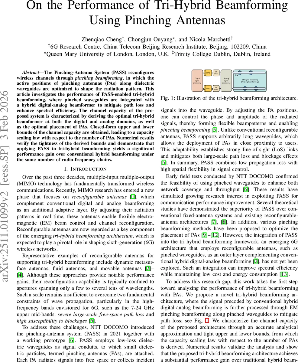
The Pinching-Antenna System (PASS) reconfigures wireless channels through \emph{pinching beamforming}, in which the active positions of pinching antennas (PAs) along dielectric waveguides are optimized to shape the radiation pattern. This article investigates the performance of PASS-enabled tri-hybrid beamforming, where pinched waveguides are integrated with a hybrid digital-analog beamformer to mitigate path loss and enhance spectral efficiency. The channel capacity of the proposed system is characterized by deriving the optimal tri-hybrid beamformer at both the digital and analog domains, as well as the optimal placement of PAs. Closed-form upper and lower bounds of the channel capacity are obtained, leading to a capacity scaling law with respect to the number of PAs. Numerical results verify the tightness of the derived bounds and demonstrate that applying PASS to tri-hybrid beamforming yields a significant performance gain over conventional hybrid beamforming under the same number of radio-frequency chains.
💡 Research Summary
The paper investigates a novel “tri‑hybrid” beamforming architecture that incorporates the Pinching‑Antenna System (PASS) into the conventional hybrid digital‑analog beamformer. PASS consists of low‑loss dielectric waveguides onto which small dielectric particles—pinching antennas (PAs)—are attached. By moving the active positions of the PAs along the waveguide, the phase and amplitude of the radiated fields can be controlled, enabling a reconfigurable outer‑layer beamforming stage that complements the digital and analog stages.
System model. A single‑cell downlink scenario is considered, where a base station equipped with (N_{\text{rf}}) RF chains serves a single‑antenna user. The transmitted signal passes through three stages: (i) a digital precoder (w_{\text{dig}}\in\mathbb{C}^{N_{\text{rf}}\times1}), (ii) an analog phase‑shifter network (W_{\text{ana}}\in\mathbb{C}^{M\times N_{\text{rf}}}) (unit‑modulus entries), and (iii) a pinching‑beamforming matrix (W_{\text{pin}}\in\mathbb{R}^{M\times N}) whose entries are the x‑coordinates of the PAs. The received signal is
\
Comments & Academic Discussion
Loading comments...
Leave a Comment