Performance Bounds of Near-Field Velocity Estimation with Modular Linear Array
Velocity estimation is a cornerstone of the recently introduced near-field predictive beamforming. This paper derives the Cramer-Rao bounds (CRBs) for joint radial and transverse velocity estimation within a predictive beamforming framework employing a modular linear array (MLA). We obtain closed-form expressions that characterize the interplay between array geometry and estimation accuracy, showing that increasing the inter-module separation enlarges the effective aperture and reduces the transverse-velocity CRB, while the radial-velocity CRB remains largely insensitive to this separation. Furthermore, we show that an MLA can achieve the same accuracy as a collocated ULA with fewer antennas and quantify the relation between inter-module spacing and antenna savings. The derived expressions are validated through simulations by comparing them with the mean-squared error (MSE) of the maximum likelihood estimator (MLE) reported in the literature.
💡 Research Summary
This paper addresses a fundamental problem in recent near‑field (NF) predictive beamforming: the joint estimation of a target’s radial (v₍r₎) and transverse (v₍t₎) velocities using a modular linear array (MLA). While prior work derived Cramér‑Rao bounds (CRBs) for velocity estimation in conventional single‑input multiple‑output (SIMO) radar or for range/angle estimation with MLAs, no analysis existed for NF velocity sensing within the predictive‑beamforming framework. The authors fill this gap by deriving closed‑form CRBs that explicitly capture the influence of MLA geometry—namely the number of modules K, the number of antennas per module M, the inter‑element spacing δ, and the inter‑module spacing L·δ.
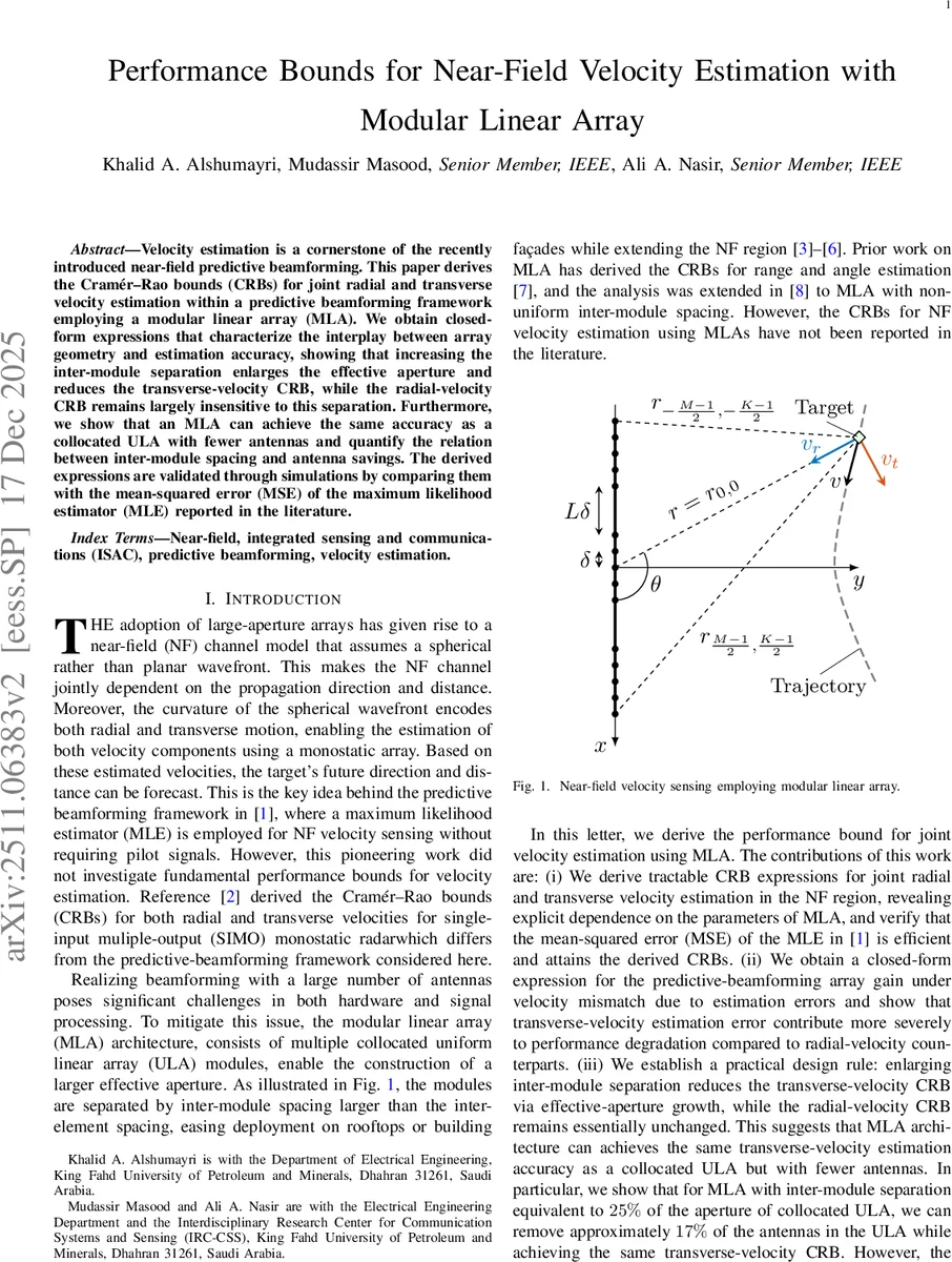
System model – The base station (BS) employs K modules placed uniformly along the x‑axis. Each module contains M isotropic antennas spaced by δ; adjacent modules are separated by L·δ, yielding a total aperture A = δ
Comments & Academic Discussion
Loading comments...
Leave a Comment