A toolbox for rendering virtual acoustic environments in the context of audiology
A toolbox for creation and rendering of dynamic virtual acoustic environments (TASCAR) that allows direct user interaction was developed for application in hearing aid research and audiology. This technical paper describes the general software struct…
Authors: Giso Grimm, Joanna Luberadzka, Volker Hohmann
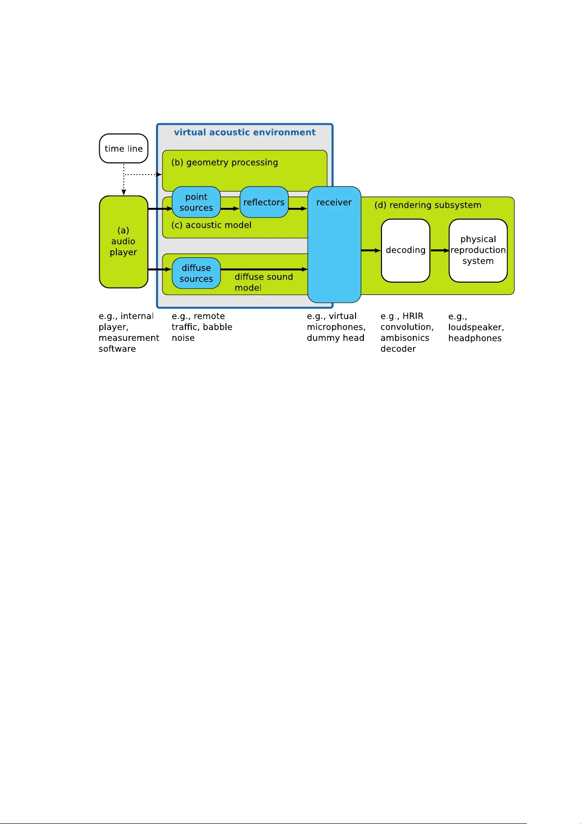
A to olb o x for rendering virtual acoustic en vironmen ts in the con text of audiology Giso Grimm 1,2,* , Joanna Lub eradzk a 1 , V olk er Hohmann 1,2 1 Medizinisc he Physik and Cluster of Excellence “Hearing4all”, Departmen t of Medical Ph ysics and Acoustics, Universit y of Olden burg, Germany 2 H¨ orT ec h gGmbH, Marie-Curie-Str. 2, 26129 Olden burg, Germany * g.grimm@uni-olden burg.de Abstract A to olbox for creation and rendering of dynamic virtual acoustic en vironments (T ASCAR) that allo ws direct user in teraction was dev elop ed for application in hearing aid researc h and audiology . This technical paper describ es the general soft ware structure and the time-domain sim ulation metho ds, i.e., transmission mo del, image source mo del, and render formats, used to produce virtual acoustic environmen ts with mo ving ob jects. Implementation-specific prop erties are described, and the computational p erformance of the system w as measured as a function of simulation complexit y . Results sho w that on commercially av ailable commonly used hardw are the sim ulation of several h undred virtual sound sources is p ossible in the time domain. 1 In tro duction Hearing aids are ev olving from simple amplifiers to complex signal pro cessing devices. Curren t hearing devices typically con tain spatially sensitive algorithms, e.g., directional microphones, direction of arriv al estimators, or binaural noise reduction, as well as automatic classification of the acoustic en vironment that is used for con text-adaptive pro cessing and amplification [25]. Sev eral of these features cannot b e tested in the curren t lab-based setups for hearing-aid ev aluation, b ecause they emplo y rather simple acoustic configurations. F urthermore, it w as shown in sev eral studies that hearing aid p erformance depends on the spatial complexity of the en vironment, and that the hearing aid p erformance in simple laboratory conditions is not a go o d predictor of the p erformance in more realistic en vironment or in the real life [36, 13, 6, 9, 24]. Finally , recen t developmen ts in hearing aid tec hnology led to an increased level of in teraction b et w een the user, the environmen t and the hearing devices, e.g., by means of motion in teraction [39, 40], gaze direction [29] or even with brain-computer in terfaces [17]. Th us, for an improv ed assessment of hearing aid benefit as well as for the dev elopment and ev aluation of user interaction tec hniques, a repro duction of complex listening en vironments in the laboratory may be b eneficial. Adv ances in computer technology in com bination with recen t multi-c hannel repro duction [7, 34, 14] and acoustic sim ulation metho ds [3, 31, 42] allo w for the repro duction of virtual acoustic en vironmen ts in the lab oratory . Limitations in repro duction and sim ulation qualit y hav e b een studied in terms of perceptual effects [ 8 , 22 ] as well as in terms of tec hnical accuracy of hearing aid b enefit prediction [ 21 , 33 ]. 1 Parts of this study have been presented at the Linux Audio Conference, Mainz, Germany , 2015. 1 These studies supp ort the general applicability of virtual acoustic environmen ts to hearing-aid ev aluation and audiology , but show that care m ust b e taken in designing the sim ulation and repro duction metho ds, to ensure that the outcome measures are not biased b y the artifacts of the applied metho ds. Sev eral further requirements apply when using virtual acoustic environmen t in hearing researc h and audiology . T o allow for a systematic ev aluation of hearing device p erformance, virtual acoustic environmen ts need to b e repro ducible and scalable in their complexit y . The presence of early reflections and late rev erb eration in the simulation is essen tial for the application of hearing aid ev aluation, since b oth of these factors may affect hearing aid p erformance [ 36 ]. F or assessmen t of user interaction, but also for the analysis of hearing aid b enefit, simulation of the effects of motion of listeners and sources migh t b e desired. These effects do not only include time-v ariant spatial cues, but also Doppler-shift and time-v ariant sp ectral cues due to com b filtering. Existing virtual acoustic environmen t engines often target authentic simulations for ro om acoustics [19, 32], resulting in a large computational complexity . They typically render impulse resp onses for off-line analysis or auralization and thus do not allow studying motion and user in teraction. Other interactiv e to ols, e.g., the SoundScap eRenderer [1], do not provide all features required here, such as ro om sim ulation and diffuse source handling. T o accommo date the requiremen ts listed ab o v e, a to olbox for acoustic scene creation and rendering (T ASCAR) w as developed as a Lin ux audio application [ 23 ] with an op en source core [37] and commercial supp ort [38]. The aim of T ASCAR is to interactiv ely render complex and time v arying virtual acoustic environmen ts via loudsp eak ers or headphones. F or a seamless integration into existing measurement to ols of psyc ho-acoustics and audiology , low-dela y real-time pro cessing of external audio streams in the time domain is applied, and in teractive mo dification of the geometry is p ossible. This tec hnical pap er aims at describing the general structure of applications in hearing aid ev aluation and audiology , the applied underlying simulation and rendering metho ds, and their sp ecific implementation. A measurement of the computational p erformance and its underlying factors is pro vided to allo w for an estimation of maximum simulation complexit y in relation to the av ailable computing p o w er. This pap er also serves as a tec hnical reference for the T ASCAR op en source softw are (T ASCAR/GPL). General structure The structure of T ASCAR can b e divided into four ma jor comp onen ts (see Figure 1 for an o verview): The audio play er (blo c k a in Fig 1) serves as a source of audio signals. The geometry pro cessor (blo c k b) controls p osition and orientation of ob jects ov er time. The acoustic mo del (blo cks c) simulates sound propagation, ro om acoustics and diffuse sounds. Finally , the rendering subsystem (blo ck d) renders the output of the acoustic mo del for a physical repro duction system. A virtual acoustic environmen t in T ASCAR is defined as a space containing several t yp es of ob jects: p oint sources (e.g., sp eak ers, distinct noise sources), diffuse sources (e.g., remote traffic, babble noise), receiv ers (e.g., dummy head), reflectors (e.g., b oundaries of a ro om) and obstacles. Source ob jects are provided with the audio con tent, delivered either by the internal audio play er mo dule, or externally e.g., from ph ysical sources, audiological measurement to ols, or digital audio workstations (DA W). Ob jects in the virtual acoustic scene can change their p ositions and orientations ov er time. Information ab out the ob ject geometry at a given time is taken either from sampled tra jectories, from algorithmic tra jectory generators, or from external devices, e.g., a jo ystick or head-motion track er (in teractive controller of an ob ject’s mo vemen t, e.g., motion of a dumm y head). 2 Fig 1. The ma jor comp onen ts of T ASCAR are the audio pla yer (a), the geometry pro cessor (b), the acoustic mo del (c) and the rendering subsystem (d). P oin t sources and diffuse sources are the in terface betw een the audio play er and the acoustic mo del. Receiv ers are the in terface b et w een the acoustic mo del and the rendering subsystem. Geometry information is exploited in the acoustic mo del to mo dify the input audio signals deliv ered by the audio play er. Mo difications p erformed by the acoustic mo del mimic basic acoustic prop erties like distance law, reflections and air absorption. The resulting sound corresp onds to the time-v arian t spatial arrangement of the ob jects in the virtual scene. Geometry data can also b e exchanged with external mo dules, e.g., game engines, to mak e the visualization consistent with the acoustic scene conten t. A t the final stage of the acoustic mo del, there is a receiv er mo del, which enco des the mo dified signals into a receiver type sp ecific render format, used subsequen tly by the rendering subsystem for the repro duction of the simulated environmen t on a ph ysical repro duction system. Sim ulation metho ds Geometry pro cessing Eac h ob ject in a virtual acoustic en vironment is determined by its p osition p ( t ) and orien tation Ω ( t ) in space at a given time t . Position is defined in Cartesian co ordinates p = ( p x , p y , p z ), and orientation is defined in the Euler angles, Ω = (Ω z , Ω y , Ω x ), where Ω z is the rotation around the z-axis, Ω y around the y-axis and Ω x around the x-axis. T ra jectories Γ for a moving ob ject are created by sp ecifying the p osition and orien tation for more then one p oint in time: Γ p = { p ( t 1 ) , p ( t 2 ) , p ( t 3 ) , . . . } Γ Ω = { Ω ( t 1 ) , Ω ( t 2 ) , Ω ( t 3 ) , . . . } , where t 1 , t 2 , · · · ∈ R are the sampling times of the tra jectory . The time v ariant p osition p ( t ) is linearly interpolated b et ween sample times of Γ p , either in Cartesian co ordinates, 3 or in spherical co ordinates relative to the origin, resp ectiv ely . The time v ariant orien tation Ω ( t ) is linearly interpolated from Γ Ω , in Euler-co ordinates. T o apply the orien tation to ob jects, a rotation matrix O is calculated from the Euler co ordinates. Acoustic mo del F or each sound source ob ject k , the acoustic mo del mo difies its asso ciated original source signal x ( t ) deliv ered by the audio play er using geometry data in to an output signal y ( t ) that is then used as input signal to a receiv er. The p erformed computations sim ulate basic acoustic phenomena as describ ed b elo w. Signals y ( t ) serve at the subsequen t stage to calculate the output of a receiver (see Section on render formats b elo w). The acoustic mo del consists of the source mo del (omni-directional or frequency-dep enden t directivity), the transmission mo del simulating sound propagation, an image source mo del, which dep ends on the reflection prop erties of the reflecting surfaces as well as on the ‘visibility’ of the reflected image source, and a receiver mo del, whic h enco des the direction of the sound source relative to the receiver into an receiv er output for further pro cessing by the rendering subsystem. Image source mo del Early reflections are generated with a geometric image source mo del, i.e., reflections are sim ulated for eac h reflecting plane surface with p olygon-shap ed b oundary by placing an image source at the p osition of the reflection. Each image source is rendered in the time domain, in the same w ay as primary sources. This is different to the more efficient “sho e-box” image source mo dels commonly used in ro om acoustic simulations [ 3 ], which calculate impulse resp onses by solving the wa v e equations. F or a first order image source mo del, each pair of primary source and reflector face creates an image source, where the plane on which the reflector lies is a symmetry axis b et w een the primary and image source (see Fig 2). The image source p osition p img is determined b y the closest p oin t on the (infinite) reflector plane p cut to the source p src : p img = 2 p cut − p src . F or higher order image source mo dels, low er order image sources are treated as primary sources leading to higher order image sources. The image source p osition itself is indep enden t of the receiver p osition. How ever, for finite reflectors there are t wo types of reflections in T ASCAR, and dep ending on the receiv er p osition it is determined which reflection type is executed (see Fig 2). If the in tersection p oint p is of the line connecting the image source with the receiver and the reflector plane lies within the reflector b oundaries, the image source is ‘visible’ in the reflector, and a ‘sp ecular’ reflection is applied. If p is is not within the reflector b oundaries, the source is ‘invisible’ from a receiver p ersp ectiv e and the ‘edge reflection’ is applied. F or ‘edge’ reflections, the apparent image source p osition is shifted so that the distance b et w een the source and receiver remains unchanged, whereas the receiver, edge of the reflector and the apparen t source p osition form one line (see Fig 2, right panel). The angle θ b y which the image source is shifted to create effectiv e image source con trols a soft-fade gain by which the source signal is multiplied g : g = cos( θ ) κ (1) The co efficien t κ = 2 . 7 was chosen for a rough approximation of diffraction of sp eec h-shap ed signals and medium-sized reflectors. If a receiver or a sound source are b ehind the reflector, the image source is not rendered. A reflector ob ject has only one reflecting side in the direction of the face normal. T o simulate the reflection prop erties of a reflector ob ject, the source s ignal is filtered with a first order lo w pass filter determined by a reflectivity co efficien t ρ , and a 4 Fig 2. Sc hematic sk etc h of the image model geometry . Left panel: ‘sp ecular’ reflection, i.e., the image source is visible within the reflector; righ t panel: ‘edge’ reflection. damping co efficien t δ , whic h can b e sp ecified for each reflector ob ject: y ( t ) = δ y ( t − f − 1 s ) + ρx ( t ) . (2) In ro om acoustics material prop erties are commonly defined by frequency dep enden t absorption co efficien ts α ( f ). These can b e calculated from the reflection filter co efficien ts ρ and δ by α ( f ) = 1 − ρ 1 − δ 1 − δ e − i 2 πf f − 1 s 2 . (3) The filter co efficien ts ρ and δ can b e derived from frequency dep enden t absorption co efficien ts b y minimization of the mean-square error b etw een desired ˜ α ( f ) and α ( f ) deriv ed from the filter co efficien ts. Source directivity F or the simulation of source directivity , the receiver p osition relative to the source p rec,r el = O − 1 src ( p rec − p src ) (4) is calculated. F requency-dep endent directivity with omni-directional characteristics at lo w frequencies and higher directivity at high frequencies is achiev ed b y controlling a lo w-pass filter by the angular distance b et ween the receiver and the source direction. The normalized relativ e receiver p osition ˜ p rec,r el is ˜ p rec,r el = p rec,r el || p rec,r el || (5) The cosine of the angular distance is then ˜ p x,rec,r el . The cut-off frequency f 6 dB defines the frequency , for which − 6 dB at ± 90 degrees are achiev ed. With ξ = π f 6 dB /f s log(2) , a first 5 order lo w-pass filter with the recursive filter co efficient c lp , c lp = 1 2 − 1 2 ˜ p x,rec,r el ξ ( f cut ) , (6) is applied to the signal, to ac hieve the frequency-dep endent directivit y , or in other w ords, the direction-dep enden t frequency characteristics. T ransmission model The transmission mo del simulates the delay , attenuation and air absorption, which dep end on the distance r ( t ) b et ween the sound source (primary or image source) and the receiv er, as well as attenuation, caused by obstacles b et ween source and receiver. P oint sources follow a 1 /r sound pressure law, i.e., doubling the distance r results in half of the sound pressure. Air absorption is approximated by a simple first order lo w-pass filter mo del with the filter co efficien t a 1 con trolled by the distance: a 1 = e − r ( t ) f s cα , (7) where f s is the sampling frequency and c the sp eed of sound. The empiric constant α = 7782 was manually adjusted to provide appropriate v alues for distances b elo w 50 meters. This approach is very similar to that of [27] who used an FIR filter to mo del the frequency resp onse at certain distances. How ever, in this approach the distance parameter r can b e v aried dynamically . The distance dep endent part of the transmission mo del without obstacles can then b e written as y ( t ) = a 1 y ( t − f − 1 s ) + (1 − a 1 ) x ( t − r ( t ) c − 1 ) r ( t ) , (8) where x ( t ) is the source signal at time t , and y ( t ) is the output audio signal of the transmission mo del. The time-v ariant delay line uses either nearest neighbor in terp olation or sinc in terp olation, dep ending on the user needs and computational p erformance of the computing system. Obstacles are mo deled by plane surfaces with p olygon-shap ed b oundaries. The acoustic signal is split in to a direct path, which is attenuated by the obstacle-sp ecific frequency-indep enden t atten uation a o , and an indirect path, to whic h a simple diffraction mo del is applied. The diffracted path is filtered with a second order low pass filter which is controlled by the shortest path from the source via the obstacle b oundary to the receiver. With the angle θ o b et w een the connection from the intersection p oint of the shortest path with the obstacle b oundary to the source p osition, and the connection from the receiv er p osition to the intersection p oin t, the cut-off frequency of the low-pass filter is f o = 3 . 8317 c 2 π a sin( θ o ) , (9) with the ap erture a = 2 p A/π defined as the radius of a circle with the same area A as the obstacle p olygon. This simple diffraction mo del is based on the diffraction on the b oundary of a circular disc [2], how ev er, p osition-dep enden t notches are not simulated. The diffracted signal is w eighted with 1 − a o and added to the atten uated signal. Diffuse sources Sound sources with lo wer spatial resolution, e.g., diffuse background noise or diffuse rev erb eration [42], are added in first order Ambisonics (FO A) format. No distance law is applied to these sound sources; instead, they hav e a rectangular spatial range b ox, 6 i.e., they are only rendered if the receiv er is within their range b ox, with a von-Hann ramp at the b oundaries of the range b ox. P osition and orientation of the range b o x can v ary with time. The size of the range b ox is typically adjusted to match the dimension of the sim ulated ro om. The diffuse source signal is rotated by the difference b et ween b o x orien tation and receiver orientation. Diffuse reverberation is not simulated in T ASCAR. T o use diffuse reverberation, the input signals of the image source mo del can b e passed to external to ols which return F OA signals, e.g., feedback-dela y netw orks or conv olution with ro om impulse resp onses in F OA format [12]. A smo oth transition b et ween early reflections from the image source mo del and diffuse reverberation based on ro om impulse resp onses can b e ac hieved by removing the first reflections from the impulse resp onses. T o account for p osition-independent late reverberation, ro om receivers can render indep enden t from the distance b et w een source and receiver, e.g., the transmission mo del can b e replaced b y a ro om-v olume dep endent fixed gain. Receiv er mo del The in terface b et ween the acoustic mo del and the rendering subsystem is the receiver. A receiv er renders the output of the transmission mo del dep ending on the relative p osition and orientation b et ween receiver and sound source. Signals from the transmission mo dels b elonging to all sound sources are summed up after direction-dep enden t pro cessing. The render format determines the num b er of channels and the metho d of enco ding the relative spatial information in to a multi-c hannel audio signal. The output signal of a receiver is z ( t ) = ( z 1 ( t ) , z 2 ( t ) , . . . , z N ( t )) . (10) The receiv er functionality can b e split in to the p anning or directional enco ding of primary and image sources y ( t ), and the de c o ding of diffuse source signals f ( t ) in first order Am bisonics format with F urse-Malham normalization (’B-format’): z ( t ) = K X k =1 w ( p rel ,k ) y k ( t ) | {z } panning + L X l =1 D ˆ O − 1 rec f l ( t ) T | {z } diffuse deco ding (11) In the panning part, the driving weigh ts w = ( w 1 , w 2 , . . . , w N ) dep end on the direction of the relativ e source p osition in the receiver co ordinate system, p rel ,k = O − 1 rec ( p k − p rec ) ; O rec is the receiver orientation matrix, and p k is the p osition of the k -th sound source. y k ( t ) is the output signal of the transmission mo del, i.e., it con tains the distance-dep enden t gain, air absorption and obstacle attenuation, for the k -th source; K is the num b er of all primary and image p oin t sources. In the diffuse deco ding part, D is the receiver-t yp e sp ecific first order Ambisonics deco ding matrix for the w , x , y and z c hannels of the first order Ambisonics signal, D = d 1 ,w d 1 ,x d 1 ,y d 1 ,z . . . . . . . . . . . . d n,w d n,x d n,y d n,z , and ˆ O − 1 rec is the rotation matrix for first order Am bisonics signals, to comp ensate the receiv er orientation. f l is the first order Am bisonics signal of the l -th diffuse source, rotated b y the source orientation; L is the num b er of all diffuse sources, including diffuse rev erb eration inputs. 7 Render formats The render formats of T ASCAR can b e divided into three categories: Virtual micr ophones simulate the characteristics of microphones. They primarily serve as a sensor in a virtual acoustic en vironment. Sp e aker-b ase d receiver types render signals whic h can drive real or virtual loudsp eak ers, used for auralization of virtual scenes. A mbisonics receiver types render the scenes to first, second or third order Ambisonics format, whic h can b e rendered to virtual microphones, loudsp eak ers or other repro duction metho ds using external deco ders. Receiv ers can render either for three-dimensional repro duction or for tw o-dimensional repro duction. In b oth cases, the directional information of the relativ e source p osition is enco ded in the normalized relativ e source p osition, ˜ p rel = p rel || p rel || . (12) Ho wev er, in the t wo-dimensional case p rel is pro jected onto x, y -plane b efore the normalization b y setting its z -comp onent to zero. In b oth cases, the acoustic mo del, con taining all distance-dep enden t effects, and the image source mo del are calculated based on the three-dimensional relativ e source p osition. Virtual microphones The virtual microphone receiver type has a single output channel. The driving weigh t is w = 1 + a ( ˜ p rel ,x − 1) . (13) It’s directivit y pattern can b e controlled b et ween omni-directional and figure-of-eight with the directivit y co efficien t a ; with a = 0 this is an omni-directional microphone, with a = 1 2 a standard cardioid, and with a = 1 a figure-of-eight. The diffuse deco ding matrix is D = √ 2(1 − a ) a 0 0 . (14) The factor √ 2 of the w -c hannel is needed to account for the F urse-Malham normalization of the diffuse signals. Sp eak er-based render formats This class of render formats con tains all types which render the signals directly to a loudsp eak er array . The n umber N and p osition s n of sp eak ers can b e user-defined; ˜ s n is the normalized sp eak er p osition. A measure of angular distance b et ween a source and a loudsp eak er is d n = 1 − ˜ s n ˜ p T rel . The most basic sp eak er-based receiver type is ne ar est sp e aker p anning (NSP). The driving weigh ts are: w n = 1 n = arg min { d n } 0 otherwise (15) Another commonly used sp eak er-based render format is tw o-dimensional ve ctor-b ase amplitude p anning (VBAP) [34]. The tw o sp eak ers n 1 and n 2 whic h are closest to the source are chosen. A gain v ector ( g n 1 , g n 2 ) T based on the normalized sp eak er p ositions and the normalized relativ e source p osition in the x, y -plane is defined: g n 1 g n 2 = ˜ s n 1 ,x ˜ s n 2 ,x ˜ s n 1 ,y ˜ s n 2 ,y − 1 ˜ p rel ,x ˜ p rel ,y (16) Then the driving w eights are w n 1 w n 2 = 1 p g 2 n 1 + g 2 n 2 g n 1 g n 2 . (17) 8 F or ambisonic panning with arbitrary order, the signal of each source is enco ded into horizon tal Ambisonics format (HO A2D). Deco ding into sp eak er signals is applied after a summation of the signals across all sources. In the deco der, the order gains can b e configured to form a ’basic’ deco der or a ’max r E ’ deco der [14]. An equal circular distribution of loudsp eak ers is assumed for this render format. Although this receiver applies principles of Am bisonics, it is a sp eaker-based receiver, b ecause enco ding and deco ding is combined. All sp eak er based receiv er types use a max r E first-order Am bisonics deco der for deco ding of diffuse sounds: D = 1 N √ 2 g ˜ s 1 ,x g ˜ s 1 ,y g ˜ s 1 ,z . . . . . . . . . . . . √ 2 g ˜ s n,x g ˜ s n,y g ˜ s n,z . (18) g is the deco der type dep enden t gain; for max r E this is g = 1 √ 2 in the tw o-dimensional case and g = 1 √ 3 in the three-dimensional case [14]. Am bisonics-based receiv ers First, second and third order receiver types were implemen ted. They follo w the channel sequence and panning w eight definition of the Ambisonics Asso ciation [4], using F urse-Malham normalization. The Am bisonics-based receivers enco de plane wa ves, i.e., they do not accoun t for near-field effects. F or tw o-dimensional enco ding, all output c hannels which are zero, w n ≡ 0, are discarded. Binaural rendering Binaural signals and m ulti-channel signals for hearing aid microphone arrays ˆ z = ( ˆ z 1 , . . . , ˆ z m ) are generated by rendering to a virtual loudsp eak er array , i.e., using a sp eak er-based render format, and applying a conv olution of the loudsp eaker signals z n with the corresp onding head-related impulse resp onses (HRIRs) h n,m for the resp ectiv e loudsp eak er directions. The HRIRs can b e either recorded (e.g., [28, 41]) or mo deled [18]. Implemen tation The implementation of T ASCAR utilizes the Jack Audio Connection Kit [ 16 ], a to ol for real-time audio routing b et w een different pieces of softw are, and b et ween softw are and audio hardw are. The audio conten t is transferred b et ween different comp onen ts of T ASCAR via JACK input and output p orts. The JACK time-line is used as a base of all time-v arying features, for data logging and as a link to the time-line of external to ols. The audio signals are pro cessed in blo cks. Time-v arian t geometry and the dep enden t sim ulation co efficien ts, e.g., delay , air absorption filter co efficien ts or panning weigh ts, are up dated at the blo ck b oundaries. The simulation co efficients are linearly in terp olated b et ween the b oundaries. This approximation by linear interpolation might b e inaccurate if the simulation co efficien ts v ary non-linearly within a blo c k, e.g., panning w eights during fast lateral mov emen ts. Render formats and algorithmic tra jectory generators are implemented as mo dules. Ob ject prop erties, like geometry data, reflection prop erties and gains, and the time-line can b e controlled interactiv ely via a net work interface. T o achiev e parallel pro cessing in T ASCAR, virtual acoustic environmen ts can b e separated in to multiple scenes. Indep endent scenes can b e pro cessed in parallel. 9 T able 1. P arameter space of the p erformance measurements. F actor V alues n umber of sources K 1, 10, 100, 256 n umber of output channels N 8, 48, 128 blo c k size P 64, 256, 1024 samples maxim um delay line length l d 1 m, 10 km render format NSP , VBAP , HO A2D CPU mo del i5-2400@3.1GHz i5-6300HQ@2.3GHz i5-6500@3.2GHz i7-7567U@3.5GHz AMD FX-4300@3.8GHz AMD Ryzen 71700 F eedback signal paths, e.g., caused by ro om coupling or external reverberation, are p ossible, but will lead to an additional blo ck of delay . The delay and pro cessing order of scenes is managed b y the JACK audio back-end. P erformance measurements F or a rough estimation of the factors of computational complexity in T ASCAR, the CPU load w as measured as a function of several relev an t factors. The p erformance measuremen ts w ere done with version 0.169 of T ASCAR. All underlying render to ols are part of the T ASCAR rep ository [37]. Metho ds CPU load C caused by audio signal pro cessing was assessed using the ’clo ck()’ system function, after pro cessing 10 seconds of white noise in each virtual sound source. The n umber of primary sources K , num b er of output channels N , blo c k size P , maximum length of delay lines l d and the render format w as v aried (see T able 1 for an ov erview of the parameter space). No image sources were pro cessed, i.e., all simulated sources w ere primary sources, and no reflectors w ere used during the p erformance measurements. Eac h measurement of a combination of K , N , P , l d and render format w as rep eated t wice. The CPU load C is time p er cycle τ P in samples divided by length of cycle P in samples. Num b er of sources and nu mber of output channels are directly related to the n umerical complexity in the receiver mo dule. The blo c k size controls the frequency of the geometry up date. Memory usage is mainly affected by the maximum delay line length. One delay line is allo cated in memory for each sound source. At 44.1 kHz sampling rate, the memory usage of the delay lines is 520 Bytes p er meter and source. Differen t render formats may differ in their numerical complexity . Results A one-w ay analysis of v ariances rev ealed that at all tested factors except for the delay line length and rep etition show ed a significant influence on the τ P at a significance level of p = 0 . 05. Thus, in the following analysis the data was av eraged across l d and rep etitions. T o provide an estimation of the contribution of different factors to the numerical complexit y , a mo del function based on the implementation was fitted to the measured 10 data: τ P = a 0 |{z} ov erhead + a 1 K | {z } geometry + a 2 K P | {z } source audio + a 3 N P | {z } postpro c. + a 4 N K P | {z } panning . (19) In this mo del, a 0 represen ts the ov erhead b y framework which is not related to the sim ulation prop erties. a 1 is an estimate of geometry pro cessing time, which is p erformed for each source, but not dep ending on the num b er of audio samples p er pro cessing blo ck P . The factor a 2 is related to source audio pro cessing time p er sample in the transmission mo del, and the pro cessing time sp en t in the receiver, which do es not dep end on the num b er of sp eakers. a 3 is an estimate of the p ost pro cessing time p er audio sample in the receiv er, which do es not dep end on the num b er of sources. a 4 is time p er audio sample for each loudsp eak er and sound source, i.e., time sp ent in the panning function of the render format. The mo del parameters were found by minimizing the mean-square error b etw een the measured and predicted CPU load C , and are shown in T able 2. An example data set for one architecture and receiver type is shown in Fig 3. Fig 3. Example CPU load (i7-7567U@3.5GHz, HOA2D receiver, P = 1024 ): Measured data (symbols) with mo del fit (Eq (19), gra y solid lines), for N = 8 sp eak ers (diamonds), N = 48 speakers (circles) and N = 128 speakers (squares). V ertical dashed lines indicate the maxim um p ossible num b er of sources, Eq (20), for the giv en hardw are. It is often required to estimate the maximum num b er of sound sources K for a given CPU, render format and loudsp eak er setup (affecting N ) and latency constrain t (affecting P ). Eq (19) can b e transformed to K max ≤ C − a 0 P − 1 − a 3 N a 1 P − 1 + a 2 + a 4 N . (20) As an example, K max w as calculated for all tested combinations of CPU mo del and receiv er type, for C = 90% and P = 1024. These results are giv en in the last tw o columns of T able 2, for N = 8 and N = 48. The results sho w that on CPU mo dels which are commonly used at the time of writing, sev eral hundred sound sources can b e simulated. F rom the tested render formats, ’HO A2D’ was most efficient, esp ecially for larger v alues of N . These results 11 T able 2. Results of the mo del fits of CPU load measuremen t. CPU format a 0 a 1 a 2 a 3 a 4 K max , 8 K max , 48 i5-2400 NSP 0.045 0.017 0.001 0.00052 7.8e-05 541 182 @3.1GHz VBAP 0.41 0.093 0.00036 0.00051 8.1e-05 812 201 HO A2D 0.52 0.02 0.001 0.00088 4.1e-05 662 288 i5-6300HQ NSP 0.028 0.0051 0.0011 0.00043 6.3e-05 548 210 @2.3GHz VBAP 0.019 0.062 0.00059 0.00046 7e-05 742 220 HO A2D 2.1e-06 0.016 0.0011 0.00069 3.7e-05 636 302 i5-6500 NSP 0.057 0.0034 0.001 0.00038 5.6e-05 615 238 @3.2GHz VBAP 0.021 0.059 0.00053 0.00042 6.2e-05 825 246 HO A2D 0.066 0.014 0.00098 0.00062 3.2e-05 714 341 i7-7567U NSP 0.099 0.0046 0.00077 0.00036 4.6e-05 790 298 @3.5GHz VBAP 0.036 0.071 0.00014 0.00033 5.2e-05 1443 329 HO A2D 0.096 0.014 0.0008 0.00053 2.7e-05 868 410 AMD FX-4300 NSP 0.099 1.8e-09 0.00019 3.2e-05 0.00021 490 89 @3.8GHz VBAP 1.4e-09 0.28 0.0012 3e-14 0.00017 316 93 HO A2D 0.056 0.019 0.0016 0.0011 4.5e-05 441 221 AMD Ryzen 71700 NSP 1.1e-06 0.015 0.00087 0.00046 6e-05 661 234 @3.6GHz VBAP 0.46 0.065 0.00027 0.00029 6.5e-05 1058 258 HO A2D 0.064 0.016 0.00083 0.00061 3.6e-05 789 339 tak e only a single core into account. On multi-core computers, more complex en vironments can b e sim ulated by splitting them into multiple environmen ts of lo wer complexit y , and rendering them in parallel. V alidation and applications The prop osed sim ulation to ol is based on established render formats, such as VBAP [ 34 ] or HOA [ 14 ]. The physical and p erceptual prop erties of these render metho ds hav e b een extensiv ely studied [30, 15, 11, 35, 1, 5, 8]. The limitations for applications in hearing aid ev aluation differ from p erceptual limitations [ 21 ]. They dep end on the sensitivity of hearing aid algorithms and the applied hearing aid p erformance measures on spatial aliasing artifacts of the render metho ds. Th us the optimal render metho d dep ends on the context of a sp ecific application of the prop osed simulation to ol. Based on the data b y [21], a sp ecific T ASCAR scene can b e designed such that it meets the requirements of an application-sp ecific receiver, e.g., a h uman head with tw o-microphone hearing aids on eac h ear. Distance p erception in human listeners is b eliev ed to b e dominated by the direct-to-rev erb eran t ratio [10]. In the prop osed simulation to ol with a simple image source mo del and p osition-indep enden t externally generated late reverberation, the distance p erception may dep end on sim ulation parameters. Thus, in a previous study the distance p erception and mo deling with ro om-acoustic parameters in simulations with T ASCAR was ev aluated [ 22 ]. It was shown in a comparison of binaural recordings in a real ro om and a simulation of the same geometry that in the simulation a distance p erception similar to real ro oms can b e achiev ed. An o verview ov er a num b er of p ossible applications is shown in Fig 4. The simplest application of T ASCAR is to play back a pre-defined virtual acoustic environmen t via m ultiple loudsp eak ers (Fig 4.a). F or sub jective audiological or psycho-acoustic measuremen ts in virtual acoustic environmen ts, without hearing aids or aided with con ven tional hearing aids, the audio input of virtual sound sources can b e provided by external measuremen t to ols (Fig 4.b). T ASCAR can also b e applied to assess hearing 12 aid (HA) p erformance in simulated virtual environmen ts, based on instrumen tal measures, or with h uman listeners, e.g., in combination with the op en Master Hearing Aid (op enMHA) [ 26 ]. Sub jectiv e or instrumental ev aluation of research hearing aids can b e p erformed b y feeding the output of the virtual acoustic environmen t directly to the inputs of a research hearing aid [ 20 ] (Fig 4.c). An example study of this use case can b e found in [24], where hearing aid p erformance in eight different virtual acoustic en vironments of different spatial complexity was assessed. T est stim uli as well as the configuration of virtual acoustic en vironment and the research hearing aid can b e con trolled from the measurement platform, e.g., MA TLAB or GNU/Octa ve (Fig 4.d). Motion data can also b e recorded from motion sensors or controllers, to interact with the en vironment in real-time, or for data logging (Fig 4.e). Fig 4. Example applications of T ASCAR and its interaction. Solid arro ws indicate audio signals, dashed arrows represent con trol information, e.g., geometry data. These use cases serv e as an illustration of typical applications of T ASCAR. The in terfaces of T ASCAR allo w for a large num b er of applications. Summary and conclusions In this technical pap er, a to olb o x for creation and rendering of dynamic virtual acoustic en vironments (T ASCAR) w as describ ed, which allows direct user interaction. This to ol w as developed for application in hearing aid research and audiology . The three main mo dules of T ASCAR - audio play er, geometry pro cessor and acoustic mo del - form the sim ulation framework. The audio play er provides the to ol with audio signals, the geometry pro cessor keeps track of the distribution of the ob jects in the virtual space, and the acoustic mo del p erforms the ro om acoustic simulation and renders the scene in to a c hosen output format. The simulation uses a transmission mo del and a geometric image source mo del in the time domain, to allow for interactivit y , and for a simple ph ysical mo del of motion-related acoustic prop erties, such as Doppler shift and comb filtering effects. T ASCAR allo ws selecting from a num b er of v arious rendering formats, customized to the needs of a range of applications, including higher order Ambisonics and binaural rendering formats. P erformance measurements quantify the influence of factors related to simulation complexit y . The results sho w that, despite some limitations in terms of complexity of the virtual acoustic en vironment, several hundred virtual sound sources can b e in teractively rendered, even ov er huge repro duction systems and on consumer-grade render hardw are. It can b e concluded that the prop osed to ol is suitable for hearing aid ev aluation. It offers a set of features, e.g., dynamic time-domain geometric image source mo del, diffuse 13 source handling, directional sources, whic h is to current knowledge unique in this com bination. Ac knowledgmen ts This study w as funded by the German Research Council DFG FOR1732. References 1. J. Ahrens and S. Sp ors. An analytical approach to sound field repro duction using circular and spherical loudsp eak er distributions. A cta A custic a unite d with A custic a , 94(6):988–999, 2008. 2. G. B. Airy . On the diffraction of an ob ject-glass with circular ap erture. T r ansactions of the Cambridge Philosophic al So ciety , 5:283, 1835. 3. J. B. Allen and D. A. Berkley . Image metho d for efficiently sim ulating small-ro om acoustics. The Journal of the A c oustic al So ciety of Americ a , 65:943, 1979. 4. Ambisonics Asso ciation. Am bisonic standards, 2008. URL http://ambisonics.ch/ . Accessed 2015. 5. E. Benjamin, A. Heller, and R. Lee. Why ambisonics do es work. In Audio Engine ering So ciety Convention 129 , 11 2010. URL http://www.aes.org/e- lib/browse.cfm?elib=15664 . 6. R. A. Bentler. Effectiveness of directional microphones and noise reduction sc hemes in hearing aids: A systematic review of the evidence. Journal of the A meric an A c ademy of Audiolo gy , 16(7):473–484, 2005. doi: doi:10.3766/jaaa.16.7.7. 7. A. J. Berkhout, D. de V ries, and P . V ogel. Acoustic con trol by wa ve field syn thesis. The Journal of the A c oustic al So ciety of Americ a , 93(5):2764–2778, 1993. doi: 10.1121/1.405852. 8. S. Bertet, J. Daniel, E. Parizet, and O. W arusfel. In vestigation on lo calisation accuracy for first and higher order am bisonics repro duced sound sources. A cta A custic a unite d with A custic a , 99(4):642–657, 2013. 9. V. Best, G. Keidser, J. M. Buc hholz, and K. F reeston. An examination of sp eec h reception thresholds measured in a sim ulated reverberant cafeteria environmen t. International Journal of Audiolo gy , (0):1–9, 2015. 10. A. W. Bronkhorst and T. Houtgast. Auditory distance p erception in ro oms. Natur e , 397(6719):517–520, 1999. 11. K. Carlsson. Obje ctive L o c alisation Me asur es in A mbisonic Surr ound-sound . PhD thesis, Master Thesis in Music T echnology , Sup ervisor: Dr. Damian Murph y . Departmen t of Sp eec h, Music and Hearing, Roy al Institute of T echnology , Sto c kholm. W ork carried out at Dept. of Electronics Universit y of Y ork, 2004. 12. A. J. Chadwick and S. Shelley . Op enair lib impulse resp onse database. h ttp://www.op enairlib.net/, 2015. Audio Lab, Universit y of Y ork. 14 13. M. Cord, R. Surr, B. W alden, and O. Dyrlund. Relationship b etw een lab oratory measures of directional adv antage and everyda y success with directional microphone hearing aids. Journal of the Americ an A c ademy of Audiolo gy , 15(5): 353–364, 2004. 14. J. Daniel. R epr´ esentation de champs ac oustiques, applic ation ` a la tr ansmission et ` a la r epr o duction de sc` enes sonor es c omplexes dans un c ontexte multim´ edia . PhD thesis, Univ ersit´ e Pierre et Marie Curie (P aris VI), Paris, 2001. 15. J. Daniel, R. Nicol, and S. Moreau. F urther inv estigations of high-order am bisonics and wa v efield synthesis for holophonic sound imaging. In Audio Engine ering So ciety Convention 114 , March 2003. 16. P . Davis and T. Hohn. Jack audio connection kit. In Pr o c e e dings of the Linux A udio Develop er Confer enc e. ZKM Karlsruhe , 2003. 17. M. De V os, K. Gandras, and S. Deb ener. T o wards a truly mobile auditory brain–computer interface: exploring the p300 to take aw ay . International journal of psychophysiolo gy , 91(1):46–53, 2014. 18. R. O. Duda. Mo deling head related transfer functions. In Signals, Systems and Computers, 1993. Confer enc e R e c or d of The Twenty-Seventh Asilomar Confer enc e on , pages 996–1000. IEEE, 1993. 19. EASE. Ease. http://ease.afmg.eu/. 20. G. Grimm, T. Herzke, D. Berg, and V. Hohmann. The Master Hearing Aid – a PC-based platform for algorithm dev elopment and ev aluation. A cta A custic a unite d with A custic a , 92:618–628, 2006. 21. G. Grimm, S. Ewert, and V. Hohmann. Ev aluation of spatial audio repro duction sc hemes for application in hearing aid research. A cta A custic a unite d with A custic a , 101(4):841–854, 2015. doi: 10.3813/AAA.918878. 22. G. Grimm, J. Heeren, and V. Hohmann. Comparison of distance p erception in sim ulated and real ro oms. In Pr o c e e dings of the International Confer enc e on Sp atial Audio , Graz, 2015. 23. G. Grimm, J. Lub eradzk a, T. Herzke, and V. Hohmann. T o olb o x for acoustic scene creation and rendering (tascar): Render metho ds and researc h applications. In F. Neumann, editor, Pr o c e e dings of the Linux Audio Confer enc e , Mainz, German y , 2015. Johannes-Guten b erg Univ ersit¨ at Mainz. 24. G. Grimm, B. Kollmeier, and V. Hohmann. Spatial acoustic scenarios in m ultichannel loudsp eak er systems for hearing aid ev aluation. Journal of the A meric an A c ademy of Audiolo gy , 27(7):557–566, 2016. 25. V. Hamacher, J. Chalupp er, J. Eggers, E. Fischer, U. Kornagel, H. Puder, and U. Rass. Signal pro cessing in high-end hearing aids: state of the art, challenges, and future trends. EURASIP Journal on Applie d Signal Pr o c essing , 2005: 2915–2929, 2005. 26. T. Herzke, H. Ka yser, F. Losha j, G. Grimm, and V. Hohmann. Op en signal pro cessing softw are platform for hearing aid research (op enMHA). In Pr o c e e dings of the Linux Audio Confer enc e , pages 35–42. Universit ´ e Jean Monnet, Sain t- ´ Etienne, 2017. 15 27. J. Huopaniemi, L. Savio ja, and M. Karjalainen. Mo deling of reflections and air absorption in acoustical spaces a digital filter design approach. In Workshop on Applic ations of Signal Pr o c essing to Audio and A c oustics (W ASP AA) . IEEE, 1997. 28. H. Kayser, J. Anem ¨ uller, T. Rohdenburg, V. Hohmann, B. Kollmeier, et al. Database of m ultichannel in-ear and b ehind-the-ear head-related and binaural ro om impulse resp onses. EURASIP Journal on A dvanc es in Signal Pr o c essing , 2009. 29. G. Kidd Jr, S. F avrot, J. G. Desloge, T. M. Streeter, and C. R. Mason. Design and preliminary testing of a visually guided hearing aid. The Journal of the A c oustic al So ciety of Americ a , 133(3):EL202–EL207, 2013. 30. C. Landone and M. Sandler. Issues in p erformance prediction of surround systems in sound reinforcemen t applications. In Pr o c e e dings of the 2nd COST G-6 Workshop on Digital Audio Effe cts (DAFx99) , Norwegian Universit y of Science and T echnology , T rondheim, Norwa y , December 1999. 31. T. Lentz, D. Schr¨ oder, M. V orl¨ ander, and I. Assenmac her. Virtual realit y system with in tegrated sound field simulation and repro duction. EURASIP Journal on Applie d Signal Pr o c essing , 2007(1):187–187, 2007. 32. G. M. Naylor. Odeon—another hybrid ro om acoustical mo del. Applie d A c oustics , 38(2-4):131–143, 1993. 33. C. Oreinos and J. M. Buchholz. Ob jective analysis of ambisonics for hearing aid applications: Effect of listener&ap os;s head, ro om reverberation, and directional microphones. The Journal of the A c oustic al So ciety of Americ a , 137(6): 3447–3465, 2015. doi: http://dx.doi.org/10.1121/1.4919330. URL http:// scitation.aip.org/content/asa/journal/jasa/137/6/10.1121/1.4919330 . 34. V. Pulkki. Virtual sound source p ositioning using vector base amplitude panning. J. Audio Eng. So c , 45(6):456–466, 1997. 35. V. Pulkki and T. Hirvonen. Localization of virtual sources in multic hannel audio repro duction. Sp e e ch and Audio Pr o c essing, IEEE T r ansactions on , 13(1): 105–119, 2005. 36. T. Rick etts. Impact of noise source configuration on directional hearing aid b enefit and p erformance. Ear and He aring , 21(3):194–205, 2000. 37. T ASCAR/GPL. T ascar/gpl. https://github.com/gisogrimm/tascar . 38. T ASCAR/H¨ orT ech. T ascar/h¨ ortech. http://www.hoertech.de/en/f- e- products/tascarpro.html . 39. B. T essendorf, A. Bulling, D. Roggen, T. Stiefmeier, M. F eilner, P . Derleth, and G. T r¨ oster. Recognition of hearing needs from b ody and eye mov ements to impro ve hearing instruments. In Pervasive Computing , pages 314–331. Springer, 2011. 40. B. T essendorf, A. Kettner, D. Roggen, T. Stiefmeier, G. T r¨ oster, P . Derleth, and M. F eilner. Identification of relev ant multimodal cues to enhance context-a ware hearing instruments. In Pr o c e e dings of the 6th International Confer enc e on Bo dy A r e a Networks , pages 15–18. ICST (Institute for Computer Sciences, So cial-Informatics and T elecomm unications Engineering), 2011. 16 41. J. Thiemann, A. Escher, and S. v an de Par. Multiple mo del high-spatial resolution hrtf measuremen ts. In Pr o c e e dings of the German annual c onfer enc e on ac oustics (DA GA) , N ¨ urnberg, 2015. 42. T. W endt, S. V an De Par, and S. D. Ewert. A computationally-efficient and p erceptually-plausible algorithm for binaural ro om impulse resp onse simulation. Journal of the Audio Engine ering So ciety , 62(11):748–766, 2014. 17
Original Paper
Loading high-quality paper...
Comments & Academic Discussion
Loading comments...
Leave a Comment