End-to-End Performance Analysis of Underwater Optical Wireless Relaying and Routing Techniques Under Location Uncertainty
On the contrary of low speed and high delay acoustic systems, underwater optical wireless communication (UOWC) can deliver a high speed and low latency service at the expense of short communication ranges. Therefore, multihop communication is of utmo…
Authors: Abdulkadir Celik, Nasir Saeed, Basem Shihada
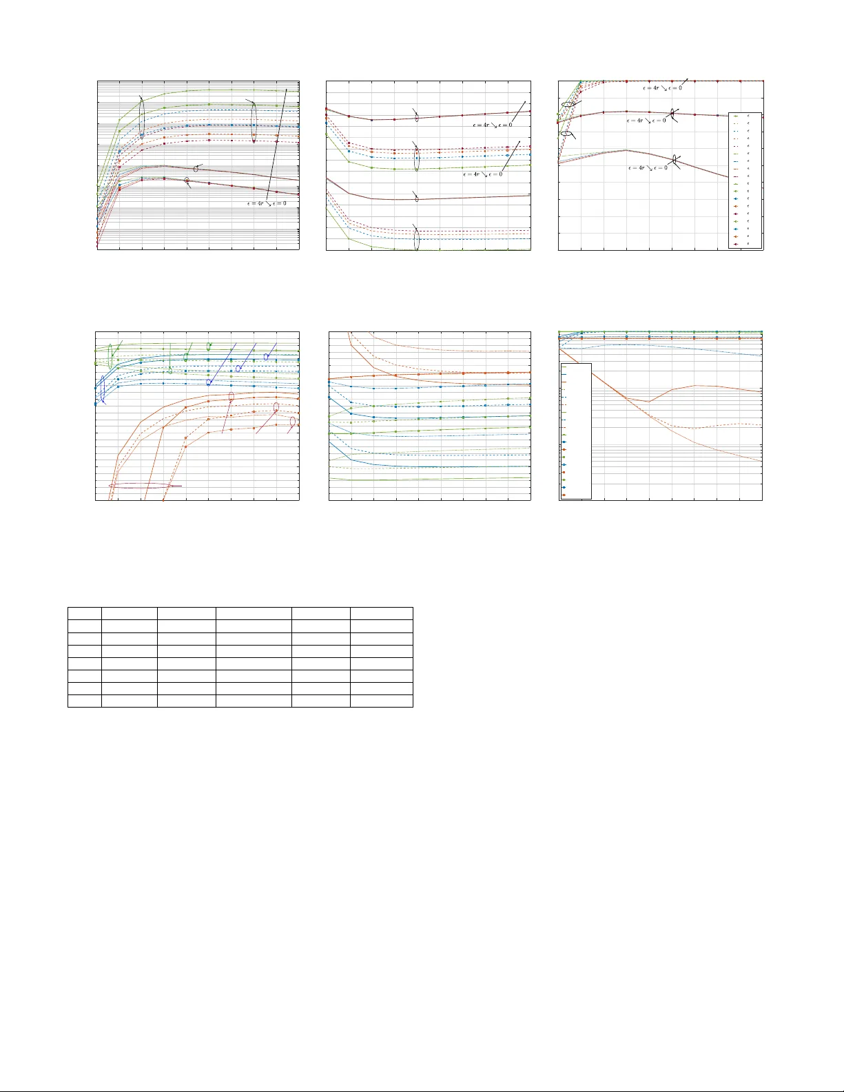
End-to-End Performance Analysis of Underwater Optical W ireless Relaying and Routing T echniques Under Location Uncertainty Abdulkadir Celik, Member , IEEE, Nasir Saeed, Member , IEEE, Basem Shihada, Senior Member , IEEE, T areq Y . Al-Naf fouri, Senior Member , IEEE, and Mohamed-Slim Alouini, F ellow , IEEE . Abstract —On the contrary of low speed and high delay acoustic systems, underwater optical wireless communication (UO WC) can deli ver a high speed and low latency service at the expense of short communication ranges. Theref ore, multihop communication is of utmost importance to improve degree of connectivity and overall performance of underwater optical wire- less networks (UO WNs). In this regard, this paper in vestigates relaying and routing techniques and provides their end-to-end (E2E) performance analysis under the location uncertainty . T o achieve rob ust and reliable links, we first consider adaptive beamwidths and derive the divergence angles under the absence and pr esence of a pointing-acquisitioning-and-tracking (P A T) mechanism. Thereafter , important E2E performance metrics (e.g., data rate, bit error rate, transmission power , amplifier gain, etc.) are obtained for two potential relaying techniques; decode & forward (DF) and optical amplify & forward (AF). W e develop centralized routing schemes for both relaying techniques to optimize E2E rate, bit error rate, and power consumption. Alternativ ely , a distributed routing protocol, namely Light Path Routing (LiPaR), is proposed by leveraging the range-beamwidth tradeoff of UO WCs. LiPaR is especially shown to be favorable when there is no P A T mechanism and available network informa- tion. In order to show the benefits of multihop communications, extensive simulations are conducted to compare different routing and relaying schemes under different network parameters and underwater en vironments. Index T erms —Decode-and-forward, amplify-and-f orward, regenerate-and-f orward, adaptive diver gence angle, pointing, acquisitioning, tracking, location uncertainty , robustness, reliability , light path routing, optical shortest path routing. I . I N T RO D U C T I O N T H E recent demand on high quality of service communica- tions for commercial, scientific and military applications of underwater exploration necessitates a high data rate, lo w latency , and long-range underwater networking solutions [1]. Fulfilling these demands is a formidable challenge for most of the electromagnetic frequencies due to the highly attenuating aquatic medium. Therefore, acoustic systems ha ve receiv ed considerable attention in the past decades. As a result of the surface-induced pulse spread and frequency-dependent attenuation, acoustic communication data rates are restrained to around tens of kbps for ranges of a kilometer , and less than kbps for longer ranges [2]. Moreover , the low propagation speed of acoustic w aves (1500 m/s) induces a high latency Authors are with Computer , Electrical, and Mathematical Sciences and Engineering Division at King Abdullah University of Science and T echnology (KA UST), Thuwal, 23955-6900, KSA. A part of this work was presented in IEEE WCNC 2018 in Barcelona, Spain [1]. [3], especially for long-range applications where real-time communication and synchronization are challenging. Alternativ ely , underwater optical wireless communication (UO WC) has the virtues of supporting high speed connections in the order of Gbps [4], [5], providing low latency as a result of the high propagation speed of light in the aquatic medium ( « 2 . 55 ˆ 10 8 m/s) [6], and enhancing security thanks to the point-to-point links [7]. Ne vertheless, the reachable UO WC range is delimited by se vere underwater channel impairments of absorption and scattering. The absorption effect refers to the energy dissipation of photons while being conv erted into other forms (e.g., heat, chemical, etc.) along the propagation path. The scattering is re garded as the deflection of the photons from its default propagation path, which is caused either by water particles of size comparable to the carrier wavelength (i.e., diffraction) or by constituents with dif ferent refraction index (i.e., refraction). Therefore, the relation between absorption and scattering primarily characterizes the fundamental tradeoff between range and beam div ergence angle. That is, a colli- mated light beam can reach remote receiv ers within a tight span whereas a wider light beam can communicate with nearby nodes in a broader span. Accordingly , the range-beamdwidth tradeoff primarily determines the connectivity and outage in underwater optical wireless networks (UO WNs) [8]. The directed nature of UO WC also necessitates efficient pointing-acquisitioning-and-tracking (P A T) mechanisms, espe- cially for the collimated light beams propagating ov er a long range. Hence, accurate node location information has a critical importance for effecti ve P A T mechanisms [9]. Howe ver , the estimated node locations may not refer to actual node positions either because of the localization errors or the random move- ments caused by the hostile underwater en vironment. These hav e negati ve impacts on the link reliability and performance as a result of the poor P A T ef ficiency . A potential solution for location uncertainty would be emplo ying adapti ve optics to provide a degree of robustness by adjusting the bandwidth to cov er a wider spatial area around the estimated recei ver location. Limited communication range and hostile underwater chan- nel conditions also entail communicating over multiple hops in order to improve both connecti vity and performance of UO WNs. In this respect, there is a dire need for analyzing the end-to-end (E2E) performance of multihop UO WCs under prominent relaying techniques. Moreov er , multihop UO WCs require effecti ve routing protocols that can tackle the range- beamwidth tradeoff and adversity of underwater en vironment. It is therefore of utmost importance to dev elop robust relaying and routing techniques which manipulate range-beamwidth tradeoff by means of adapti ve optics, which is main focus of this paper . A. Related W orks Recent ef forts on UOWC can be ex emplified as follo ws: Arnon modeled three types of UO WC links: line-of-sight (LoS), modulating retroreflector , and non-LoS (NLoS) [10]. In [11], authors model and e valuate underwater visible light communication (UVLC) vertical links by dividing the UWON into layers and taking account of the inhomogeneous char- acteristics (e.g., refracti ve inde x, attenuation profiles, etc.) of each layer . Experimental e v aluation of orthogonal frequenc y division multiplexing based UVLC is conducted in [12] and performance of automatic repeat request (ARQ) based UVLC system is analyzed in [13]. Considering Poisson point process based spatial distribution of nodes, V av oulas et. al. analyzed the k -connecti vity of UO WNs under the assumption of omni- directional communications [14]. T o take the directivity of UO WC into account, the k -connecti vity analysis of UOWNs is readdressed in [8] which is further e xtended to in vestigate impacts of connectivity on the localization performance [15]. Akhoundi et. al. introduced and inv estigated a potential adaptation of cellular code division multiple access (CDMA) for UOWNs [16], [17]. In [18], authors characterized the per- formance of relay-assisted underwater optical CDMA system where multihop communication is realized by chip detect- and-forward method. Assuming identical error performance at each hop, Jamali et. al. consider the performance analysis of multihop UOWC using DF relaying [19]. Since the commonly adopted Beer-Lambert UO WC channel model assumes that the scattered photons are totally lost, authors of [20] modify this renown model to consider the receiv ed scattered photons by a single parameter which is a function of transceiv er parameters and water type. Thereafter , they consider a dual-hop UVLC system and determine optimal relay placement to minimize the bit error rate (BER) for both DF and AF relaying. B. Main Contrib utions The main contributions of this paper can be summarized as follows: ‚ T o model the displacement of the actual locations from the estimates, we consider an uncertainty disk whose radius is a design parameter that depends on the localiza- tion accuracy and/or mobility of nodes. Assuming nodes are equipped with adapti ve optics, robust UOWC links are provisioned by deri ving the diver gence angles for scenarios with and without a P A T mechanism. Numerical results show that location accurac y and effecti ve P A T mechanism are crucial to reach a desirable performance. ‚ W e inv estigate and compare two prominent relaying techniques; decode & forward (DF) and optical am- plify & forward (AF), each of which is analyzed for important E2E performance metrics. For both relaying methods, closed form expressions are deriv ed for various performance metrics, e.g., E2E-Rate, E2E bit error rate (BER), transmission po wer , amplifier gain, etc. F or a giv en path, we also formulate and solv e minimum total power consumption problems under both DF and AF relaying schemes. ‚ In light of the adaptiv e diver gence angles and E2E performance analysis, both centralized and distributed routing protocols are developed based on the av ailability of global or local network state information, respectively . The centralized techniques employ variations of shortest path algorithms which are tailored to achiev e various objectiv es such as maximum achiev able E2E-Rate, mini- mum E2E-BER, and minimum total power consumption. By manipulating the range-beamwidth tradeoff, we pro- pose Light Path Routing (LiPaR); a distrib uted routing protocol that combines tra veled distance progress and link reliability . Obtained results show that LiPaR can provide a superior performance compared to centralized schemes without a P A T mechanism. C. P aper Organization The remainder of the paper is organized as follows: Section II introduces the system model. Section III presents the uncertainty disk model and deriv es the adaptiv e div ergence angles. Section IV analyzes and compares DF and AF relaying techniques. Section V develops the centralized and distributed routing protocols. Section VI presents the numerical results. Finally , Section VII concludes the paper with a fe w remarks. I I . S Y S T E M M O D E L W e consider a two-dimensional underwater optical wireless network (UO WN) which consists of a M surface stations/sinks (SS) and N nodes/sensors as shown in Fig. 1. The SSs are responsible for disseminating the data collected from sensors to mobile or onshore sinks. Nodes are equipped with two optical transceiv ers to enable bi-directional connections be- tween sensors and SSs [c.f. Fig. 2]. Transmitters are assumed to be capable of adapting their beam di vergence angle θ n within a certain range, i.e., θ min ď θ n ď θ max . The location estimates of the SS m and node n are denoted by ` m “ r x m , y m s , @ m P r 1 , M s , and ` n “ r x n , y n s , @ n P r 1 , N s , respectiv ely . Like wise, actual locations of the SS m and node n are denoted by ` ˚ m “ r x ˚ m , y ˚ m s , @ m P r 1 , M s , and ` ˚ n “ r x ˚ n , y ˚ n s , @ n P r 1 , N s , respecti vely . In addition to ` n , node n is a ware of ` m , @ m . According to the Beer’ s law , aquatic medium can be char- acterized for wav elength λ as a combination of absorption and scattering effects, i.e., e p λ q “ a p λ q ` b p λ q where a p λ q , b p λ q and e p λ q are absorption, scattering and extinction coefficients respectiv ely . These coefficients v ary with water types (e.g., clear , harbor , turbid. etc.) and water depths (e.g., shallo w , deep, etc.). The propagation loss factor of the LoS channel between node i ( n i ) and node j ( n j ) is defined as follo ws L j i “ exp # ´ e p λ q d ij cos p ϕ j i q + , (1) Fig. 1: Illustration of UOWNs with multiple sinks. L o n g R a n g e N a r r o w B e a m D i v e r g e n c e A n g l e n 2 S h o r t R a n g e W i d e B e a m D i v e r g e n c e A n g l e sw 2 j j i j i P o i n t i n g V e c t o r d s w d l n j i d N o d e F o r w a r d R e c e i v e r B a c k w a r d R e c e i v e r B a c k w a r d T r a n s m i t t e r F o r w a r d R e c e i v e r Fig. 2: Demonstration of the system model and range-beamwidth tradeoff. where d ij is the perpendicular distance and ϕ j i is the angle between the receiver plane and the transmitter-recei ver trajec- tory , i.e., the pointing v ector of the transmitter . On the other hand, geometric loss of the LoS channel is given as [21] g j i “ $ & % A j d 2 ij cos p ϕ j i q 2 π r 1 ´ cos p θ i qs ξ p ψ j i q , ´ π { 2 ď ϕ j i ď π { 2 0 , otherwise , (2) where A j is the receiv er aperture area of n j , θ j i is the half-beamwidth div ergence angle of n i 1 , and ξ p ψ j i q is the concentrator gain, that is defined as ξ p ψ j i q “ # ι 2 sin 2 p Ψ j q , 0 ď ψ j i ď Ψ j 0 , ψ j i ą Ψ j , (3) ψ j i is the angle of incidence w .r .t. the receiver axis, Ψ j is the concentrator field-of-vie w (F oV) 2 , and ι is the internal refractiv e index. As shown in Fig. 2, UO WC channel characteristics pose a fundamental tradeoff between communication range and di ver - gence angle (i.e., beamwidth). That is, a wide di ver gence angle 1 θ j i is measured at the point where the light intensity drops to 1 { e of its peak. 2 Ψ j can be π { 2 and down to π { 6 for hemisphere and parabolic concen- trators, respectively . i j r A d a p t i v e B e a m w i d t h s w i t h P A T ( a ) U n c e r t a i n t y D i s k M o d e l . . . . . . . . . A l i g n m e n t A f t e r T h e P A T P r o c e s s . ( b ) P e r f e c t P A T C a s e ( c ) P A T w i t h l o c a t i o n u n c e r a i n t y j i r R r R E s t i m a t e d L o c a t i o n T a n g e n t R Fig. 3: Adaptiv e beamwidths for P A T mechanisms. can reach nearby nodes whereas a narrow diver gence angle is able to reach distant destinations. Therefore, manipulation of this tradeoff has significant impacts on sev eral performance metrics such as the degree of connectivity , distance progress for the next hop, routing efficiency , and E2E performance. For instance, a wide div ergence angle provides more path div ersity at the expense of a higher number of hops which increases energy consumption and E2E delay . On the other hand, a narrow diver gence angle can deli ver a desirable performance ov er long distances, which requires precise and agile P A T mechanisms to keep the transcei vers aligned ov er long ranges. Throughout the paper , this tradeoff is to be discussed in the E2E performance analysis of dif ferent relaying techniques and the design of the routing protocols. I I I . A DA P T I V E B E A M W I D T H A N D P A T M E C H A N I S M For a reliable and well-connected transmission, the inherent directivity of UOWC requires perfectly aligned point-to-point links between the transceiv ers. First and foremost information needed for a proper alignment is node coordinates that can be obtained either by pure optical [22] or hybrid acoustic-optical localization algorithms [23]. Nonetheless, localization errors introduce uncertainty over the location estimates, which may be further e xacerbated by the random mo vements of nodes due to the hostile underwater conditions. Thus, the accuracy of location estimates plays an essential role in the E2E performance of the multihop communication. One solution to this problem is adaptiv ely changing the properties of the light beam. Indeed, misalignment caused by the location uncertainty can be alleviated by adapting the diver gence angle to cover a larger spatial region at the cost of degraded performance. In the remainder , we therefore probe an initial in vestigation into the rob ust diver gence angles and its impact on the E2E performance by considering the follo wing three dif ferent cases. A. Divergence Angles for P AT with P erfect Location Estimates In the ideal case, estimated and actual locations are the same (i.e., “ 0 ), the pointing v ector is aligned to n j , and div ergence angle is adjusted to e xactly cover the node frame, S S x y i j R j j A d a p t i v e B e a m w i d t h s I n i t i a l A l i g n m e n t T o w a r d s t h e S S Fig. 4: Adaptive half-beamwidths under the receiver location uncer- tainty . which is shown by plaid sectors in Fig. 3.b. Accordingly , the full diver gence angle of the perfect P A T scenario is giv en by θ pp ij p r q “ max ˆ θ min , arcsin ˆ r d ij ˙˙ , (4) which follows from the la w of sines and the fact that radius is perpendicular to the tangent points. B. Divergence Angles for P AT under Location Uncertainty The location uncertainty can be caused by estimation errors of localization method and/or the random mo vements of the transceiv ers, which results in a radial displacement of the actual location from the estimated location. As shown in Fig. 3.a, we model node locations by an uncertainty disk centered at the location estimates and has a radius of R “ r ` where r is the radius of the node frame and is the uncertainty metric. Under the location uncertainty , the div ergence angle must be calculated based on the w orst case scenarios where the transmitter is located at one of the tangents on the uncertainty disk [c.f. Fig. 3.c]. In this case, the di ver gence angle is twice of the perfect angle cov ering the uncertainty disk, i.e, θ ip ij p , r q “ max ˆ θ min , arcsin ˆ 2 ` r d ij ˙˙ , (5) which can be defined as a robust di vergence angle as it assures the worst case beamwidth to establish a link between the transceiv ers. Noting that this is the first step of the P A T procedure, i.e., pointing, acquisitioning and tracking are the next steps to keep nodes aligned via feedbacks, which results in Fig. 3.b. Although de veloping a P A T mechanism is out of our scope, our purpose is to sho w its critical role in the multihop UOWN performance. C. Divergence Angles under the Absence of P AT In the absence of the P A T mechanism, we assume that nodes keep their body frame directed tow ards the location of the closest SS to align transmitter’ s pointing vector with the SS receiv er . Although pointing to a certain location is not possible, nodes can still reach nodes within a certain angle around the pointing vector by adjusting the beamwidth. For the sake of a clear presentation, let us first consider the location uncertainty in the receiv er node only [c.f. Fig. 4], where the origin of the local Cartesian coordinate system is y ’ ’ y y ’ x ’ ’ x x ’ o ’ ’ o o ’ Fig. 5: Illustration of adaptiv e beamwidth calculations under the transceiv er location uncertainty . set to the estimated transmitter location, i.e., o “ ` i “ ` ˚ i . In this local coordinate system, the locations of n j and the destination SS m (SS m ) are given by ˜ ` j “ r x j ´ x i , y j ´ y i s and ˜ ` m “ r x m ´ x i , y m ´ y i s , respectively . Hence, the angles between the x-axis and vectors pointing n j ( Ý Ý Ñ ` i ` j ) and the SS m ( Ý Ý Ñ ` i ` m ) are given by ϕ j i “ arctan ˆ y j ´ y i x j ´ x i ˙ and φ s i “ arctan ˆ y m ´ y i x m ´ x i ˙ , (6) respectiv ely . Accordingly , the div ergence angle that is centered around Ý Ý Ñ ` i ` m cov ering the uncertainty disk is gi ven by (7) where sgn p¨q is the signum function. Fig. 4 illustrates the half div ergence angle of the first and second cases in (7) by green/red and blue colors, respecti vely . The last case is the scenario where Ý Ý Ñ ` i ` m passes through the uncertainty disk. Similar to the previous subsection, we consider the wost case scenario when there is uncertainty about both recei ver and transmitter locations. Therefore, we consider two additional local coordinates originated at tangent locations [c.f. Fig. 5] which are given by o 1 “ ” x i ` cos ´ γ s i ` π 2 ¯ , y i ` sin ´ γ s i ` π 2 ¯ı (8) o 2 “ ” x i ` cos ´ γ s i ´ π 2 ¯ , y i ` sin ´ γ s i ´ π 2 ¯ı . (9) Noting that γ s i is the same in all local coordinates, ϕ j i for o 1 ( ϕ 1 ij ) and o 2 ( ϕ 2 ij ) should be obtained as in (6). By substituting ϕ 1 ij and ϕ 2 ij into (7), one can obtain div ergence angles for transmitters located at tangent points o 1 ( θ 1 ij ) and o 2 ( θ 2 ij ), respectiv ely . In case of the location uncertainty at both sides, the div ergence angle is then given by θ j i “ max ´ θ min , max ´ θ o ij , θ 1 ij , θ 2 ij ¯¯ . (10) I V . P E R F O R M A N C E A N A L Y S I S O F R E L A Y I N G T E C H N I Q U E S In this section, we consider the E2E performance analysis of potential relaying techniques for an arbitrary multi-hop path from a source node to one of the sink nodes. Such a path is defined as an ordered set of nodes, i.e., H o ù s “ t h | 0 ď h ď H u where H “ | H o ù s | is the number of hops and the first (last) element represents the source (sink). θ o ij “ $ ’ ’ ’ ’ ’ & ’ ’ ’ ’ ’ % θ ip ij p , r q , if φ s i “ ϕ j i 2 ˇ ˇ ˇ φ s i ´ ϕ j i ˇ ˇ ˇ ` θ pp ij p R q 2 , if sgn p φ s i q “ sgn p ϕ j i q Ź φ s i ‰ ϕ j i 2 ˇ ˇ ˇ ϕ j i ´ φ s i ˇ ˇ ˇ ` θ pp ij p R q 2 , if sgn p φ s i q ‰ sgn p ϕ j i q 2 max ´ ˇ ˇ ˇ φ s i ´ ´ ϕ j i ` θ pp ij p R q 2 ¯ ˇ ˇ ˇ , ˇ ˇ ˇ φ s i ´ ´ ϕ j i ´ θ pp ij p R q 2 ¯ ˇ ˇ ˇ ¯ , if ϕ j i ` θ pp ij p R q 2 ě φ s i ě ϕ j i ´ θ pp ij p R q 2 (7) A. Decode & F orward Relaying In DF transmission, the receiv ed optical signal at each hop is con verted into electrical signal, then decoded, and finally re-encoded before retransmission for the ne xt hop. Thus, the DF relaying requires high speed data con verters, decoders, and encoders to sustain the achie v able data rates in the order of Gbps. For an arbitrary path, receiv ed power at node h is giv en as P r h “ P t h ´ 1 η t h ´ 1 η r h G h h ´ 1 , @ h P r 1 , H s , (11) where P t h ´ 1 is the average optical transmitter power of previ- ous node, η t h ´ 1 is the transmitter efficienc y of node h ´ 1 , η r h is the receiver ef ficiency of node h , and G h h ´ 1 “ L h h ´ 1 g h h ´ 1 is the composite channel gain. The most common detection technique for O WC is intensity-modulation/direct-detection (IM/DD) with on-of f keying (OOK). Assuming that photon arriv als follows a Pois- son process, photon arri val rate of node h is giv en as [24] f h p p q “ P h η d h λ R h h ´ 1 T } c , @ h P r 1 , H s , (12) where P h is the observed power at node h , η d h is the detector counting efficiency , R h h ´ 1 is the transmission rate for the hop p h ´ 1 , h q , T is pulse duration, } is Planck’ s constant, and c is the underw ater speed of light. Hence, the photon counts when binary ’0’ transmitted is gi ven by p 0 h fi f h p P n q where P n “ P dc ` P bg is the total noise power , P dc is the additi ve noise power due to dark counts and P bg is the background illumination noise po wer . Similarly , the photon counts when binary ’1’ transmitted is given by p 1 h fi f h p P r h ` P n q . Assuming a lar ge number of photon reception, the Poisson distribution can be approximated by a Gaussian distribution as per the Central Limit Theorem. F or a given data rate, ¯ R , the BER of a single hop is gi ven by [10] P h h ´ 1 “ 1 2 erfc ˜ c T 2 „ b p 1 h ´ b p 0 h ¸ (13) where erfc p¨q is the complementary error function. For a certain BER threshold, ¯ P e i,j , data rate of the hop p h ´ 1 , h q is deriv ed from (13) as R h h ´ 1 “ η d h λ 2 } c « a P r h ` P n ´ ? P n erfc ´ 1 p 2 ¯ P h h ´ 1 q ff 2 , (14) which is inv ersely proportional to the BER. Following from (11)-(14), minimum transmit power to ensure a predetermined rate ¯ R h h ´ 1 and BER ¯ P e h ´ 1 ,h is giv en by P t h ´ 1 “ a 2 ` 2 a ? P n G h h ´ 1 λη t h ´ 1 η r h η d h (15) where a “ erfc ´ 1 p 2 ¯ P h h ´ 1 q c 2 ¯ R h h ´ 1 } c η d h λ . F or a gi ven error and data rate, communication range between tw o generic nodes ( i, j ) is gi ven by D j i “ 2 e p λ q W 0 ˜ e p λ q 2 ? c cos p φ j i q ¸ (16) where W 0 p¨q is the principal branch of product logarithm function, c “ 2 bπ r 1 ´ cos p θ i qs A j cos p φ j i q ξ p ψ j i q and b “ a 2 ` 2 a ? P n P t h ´ 1 λη t h ´ 1 η r h η d h . W e refer interested readers to Appendix A for deriv ation details. Before proceeding into the E2E performance analysis, it is necessary to discuss single-hop performance in light of Section III and the abo ve deri vations. For a gi ven transmit power and communication range, increasing the di ver gence angle deteriorate the P e h ´ 1 ,h and R h h ´ 1 , which are in versely propor- tional as per (13) and (14). On the contrary , communication range decreases by increasing (decreasing) R h h ´ 1 ( P e h ´ 1 ,h ) and decreasing (increasing) the transmit power (diver gence angle). Noting the coupled relation of the di ver gence angle with all these metrics, single-hop performance analysis clearly sho ws the need for ef fectiv e P A T mechanisms to obtain a superior E2E performance, which is analyzed next. Denoting X h as the Bernoulli random variable which rep- resent the erroneous decision of node h , total number of incorrect decision made along the path is giv en as X “ ř H h “ 1 X h . Assuming X h ’ s are independent but non-identically distributed, X is a Poisson-Binomial random variable. Since a transmitted bit is receiv ed correctly at the sink if the number of erroneous detection is e ven, E2E BER is derived as P DF E 2 E “ ÿ j P A ÿ B P F j ź k P B P k k ´ 1 ź l P B c ` 1 ´ P l l ´ 1 ˘ (17) where A “ t 1 , 3 , . . . , H u is the set of odd numbers and F j is the set of all subsets of j integers that can be selected from A . P E 2 E can be expeditiously calculated from polynomial coefficients of the probability generating function of X in O p A log A q where A is the cardinality of A [25]. Notice that X reduces to a Binomial v ariable if all hops are assumed to be identical as in [19] , which is hardly the case in practice. The achiev able E2E rate is determined by the minimum of the data rates along the path, i.e., R DF E 2 E “ min 1 ď h ď H ` R h h ´ 1 ˘ , (18) which implies that a predetermined E2E data rate ¯ R E 2 E requires R h h ´ 1 ě ¯ R E 2 E , @ h P r 1 , H s . Accordingly , P 1 formulates the optimization problem which minimizes the total h h H 1 t h P 1 r h n h P PA P ASE h P h A r h P t h P t h 1 R e c e i v e r E f f i c i e n c y R e c e i v e r N o i s e A m p l i f i e r A S E N o i s e T r a n s m i t t e r E f f i c i e n c y C h a n n e l G a i n T x P o w e r o f N o d e h - 1 T x P o w e r o f N o d e h N O D E h Fig. 6: Receiv er diagram for the optical AF and RF relays. transmission powers while ensuring a target E2E BER rate, ¯ P E 2 E , and E2E data rate by setting R h h ´ 1 “ ¯ R E 2 E , @ h . P 1 : min P 1 T P t P 1 1 : s.t. log p P E 2 E q ď log ` ¯ P E 2 E ˘ P 2 1 : 0 ĺ P ĺ 0 . 5 (19) where P is the BER vector of the path, 1 T is the transpose of vector of ones, and ĺ denotes the pairwise inequality for v ectors. Based on the mild assumption of ensuring each hop has a BER no more than 0 . 5 , P 1 can be shown to be a con vex problem using the log-concavity of the Poisson- Binomial distribution. W e refer interested readers to Appendix B for a formal con ve xity analysis of P 1 . B. Optical Amplify & F orwar d Relaying Although DF greatly improves the E2E performance by limiting the background noise propagation, it introduces extra power consumption and signal processing delay . Furthermore, synchronization and clock recov ery are additional challenges to be tackled in Gbps links. Alternatively , the AF relaying ex ecutes optical-to-electrical (OEO) conv ersion at each node, which amplifies the recei ved signal electrically and then re- transmits the amplified signal for the ne xt hop. The main drawback of the AF transmission is propagation of noise added at each node, which is amplified and accumulated through the path. As a remedy to costly OEO conv ersion, all optical AF relaying has the adv antages of realizing the high speed transmissions without the need for OEO conv ersion and sophisticated optoelectronic de vices. As illustrated in Fig. 6, amplified and transmitted power of all-optical AF scheme can be modeled for intermediate nodes 1 ď h ď H ´ 1 as follows P r h “ P t h ´ 1 η t h ´ 1 η r h G h h ´ 1 ` P n , (20) P t h “ A h P r h ` P a h , (21) where P n “ P bg ` P dc is the local noise at the receiv er , A h is the amplifier gain, P a “ N h o B is the amplified spontaneous emission (ASE) noise that is modeled as an additive zero- mean white Gaussian, N h o “ } f 0 ` G h h ´ 1 ´ 1 ˘ n sp is the power spectral density per polarization, f 0 is the frequenc y , n sp is spontaneous emission parameter of the amplifier , and B is the amplifier bandwidth [26]. By assuming the independence of signals, channel gains, and noises, amplified and transmitted powers at node h can be respectiv ely written in the following generic form P r h “ P 0 t h ´ 1 ź i “ 1 A i h ´ 1 ź j “ 0 η t j h ź k “ 1 η r k h ź l “ 1 G l l ´ 1 ` h ÿ i “ 1 P n h ´ 1 ź j “ i A j h ´ 1 ź k “ i η t k h ź l “ i ` 1 η r l h ź m “ i ` 1 G m m ´ 1 ` h ´ 1 ÿ i “ 1 P a h ´ 1 ź j “ i ` 1 A j h ´ 1 ź k “ i η t k h ź l “ i ` 1 η r l h ź m “ i ` 1 G m m ´ 1 , (22) P t h “ P 0 t h ź i “ 1 A i h ´ 1 ź j “ 0 η t j h ź k “ 1 η r k h ź l “ 1 G l l ´ 1 ` h ÿ i “ 1 P n h ź j “ i A j h ´ 1 ź k “ i η t k h ź l “ i ` 1 η r l h ź m “ i ` 1 G m m ´ 1 ` h ÿ i “ 1 P a h ź j “ i ` 1 A j h ´ 1 ź k “ i η t k h ź l “ i ` 1 η r l h ź m “ i ` 1 G m m ´ 1 , (23) which follo ws from the recursion of (20) and (21). Because of the propagating noise along the path, there is no a unique way of ensuring a target E2E performance. Ho we ver , a practical and tractable means of analyzing the E2E performance is fixing the transmission power at each hop. Noting that the combination of background light and dark current noise is more dominant than the ASE noise [27], the amplifier gain can be calculated as A h “ P t G h h ´ 1 η t h ´ 1 η r h ` P n (24) which is obtained by substituting (20) into (21), equalizing (21) to a fixed transmission power P t , and then solving for A h . Let us denote the transmitted signal-to-noise-ratio (SNR) at the source node as γ “ P t P n and the recei ved SNR in relay node h as γ h . By substituting (24) into (23) and neglecting the ASE related last term of (23), the recei ved SNR at the sink node can be obtained after some algebraic manipulations as γ H “ 1 ś H h “ 1 ´ 1 ` 1 γ h ¯ ´ 1 (25) where γ h “ G h h ´ 1 η t h ´ 1 η r h γ . Accordingly , the E2E-BER of optical AF relaying o ver an arbitrary route is gi ven by P AF E 2 E “ 1 2 erfc ¨ ˝ c T p 0 h 2 » – g f f e ś H h “ 1 ` 1 ` γ ´ 1 h ˘ ś H h “ 1 ` 1 ` γ ´ 1 h ˘ ´ 1 ´ 1 fi fl ˛ ‚ (26) which is derived by re writing (13) for γ H . F or a gi ven E2E- BER target ¯ P E 2 E , the achiev able E2E data rate of AF scheme is deriv ed as R AF E 2 E “ P n η d h λ „ c ś H h “ 1 p 1 ` γ ´ 1 h q ś H h “ 1 p 1 ` γ ´ 1 h q ´ 1 ´ 1 2 2 } c “ erfc ´ 1 ` 2 ¯ P E 2 E ˘‰ 2 , (27) which follows from (12) and (26). Accordingly , the minimum total transmit po wer , that ensures a gi ven E2E data and error rate pair , can be obtained by solving the following problem P 2 : min 0 ď P t ď ˆ P t H P t s.t. R AF E 2 E ě ¯ R E 2 E (28) where ˆ P t is the maximum transmit power . Since γ H is a monotonically increasing function of P t , the optimal transmit power P ‹ t can be easily obtained by standard line search methods. Accordingly , optimal amplifier gains, A ‹ h , @ h , that assures minimum E2E energy cost can be calculated by substituting P ‹ t into (24). V . C E N T R A L I Z E D A N D D I S T R I B U T E D R O U T I NG S C H E M E S Depending on the available netw ork information, routing protocols can be designed either in distrib uted or centralized fashion. In this sense, distributed solutions are suitable for scenarios where nodes ha ve local information about the net- work state of its neighborhood. On the other hand, centralized routing relies upon the av ailability of the global network topol- ogy and thus yields a superior E2E performance. Howe ver , it is worth mentioning that collecting a global network state information may yield extra communication ov erhead and energy cost. Therefore, the remainder of this section addresses centralized and distributed UOWN routing techniques. A. Centralized Routing Sc hemes Let us represent the netw ork by a graph G p V , E , Ω q where V is the set of sensor nodes, E is the set of edges, and Ω P R N ˆ N is the edge weight matrix that can be designed to achiev e different routing objectives. In this respect, the remainder of this section considers three primary routing objecti ves: minimum E2E-BER, maximum E2E-Rate, and minimal total power consumption. 1) Minimum E2E-BER Routing: The main goal of this routing scheme is to find a path that minimizes the E2E-BER, P DF E 2 E , while ensuring a predetermined E2E data rate, ¯ R E 2 E . As previously shown in (18), we satisfy this constraint by setting the data rate of each hop to ¯ R E 2 E . By neglecting the fortunate ev ents of corrections at e ven number of errors, we make the follo wing mild assumption for the DF relaying; the sink can correctly detect a bit if-and-only-if it is successfully detected at each hop. Thus, we equiv alently consider the maximization of the E2E bit success rate (BSR), BSR fi ś H h “ 1 ` 1 ´ P h h ´ 1 ˘ , instead of minimizing the P DF E 2 E . Since the shortest path algorithms are only suitable to additiv e costs, BSR maximization can be transformed from the multiplication into a summation as follows max @p o ù s q p BSR q “ max @p o ù s q log ˜ H ź h “ 1 ` 1 ´ P h h ´ 1 ˘ ¸ (29) “ min @p o ù s q ˜ H ÿ h “ 1 ´ log ` 1 ´ P h h ´ 1 ˘ ¸ (30) where o ù s denotes an arbitrary path. By putting the product into an additive form, the maximum BSR route can be calculated by Dijkstra’ s shortest path (DSP) algorithm with a time complexity of O ` | V | 2 ˘ . Accordingly , edge weights is set to the non-negati ve values of Ω j i “ ´ log p 1 ´ P j i q where P j i is the BER between n i and n j . Once the route is calculated, P DF E 2 E can be computed by substituting ¯ R E 2 E into (17). In the case of AF relaying, optimal route must account for the noise propagation along the path. Follo wing from (26) and (27), both E2E data rate and BER can be minimized by maximizing the SNR at the destination node, γ H . Based on the same rationale in (29), maximizing the SNR can be transformed into an additi ve form as follows max @p o ù s q γ H “ min @p o ù s q H ź h “ 1 ` 1 ` γ ´ 1 h ˘ (31) “ min @p o ù s q log ˜ H ź h “ 1 ` 1 ` γ ´ 1 h ˘ ¸ (32) “ min @p o ù s q ˜ H ÿ h “ 1 log ` 1 ` γ ´ 1 h ˘ ¸ (33) which can also be calculated using the DSP algorithm by setting non-negati ve edge weights to Ω j i “ log ´ 1 ` 1 γ j i ¯ where γ j i is the SNR between n i and n j . Once the route is calculated, the P AF E 2 E can be calculated by substituting ¯ R E 2 E into (26). 2) Maximum E2E Data Rate Routing: Our tar get in this routing scheme is to find a path that maximizes E2E data rate while ensuring a predetermined E2E-BER, P DF E 2 E , which is non-trivial since the P DF E 2 E is coupled with the hop counts as well as R DF E 2 E . Therefore, we first relax the problem by fixing the BER at each edge and then find the optimal route with the maximum R DF E 2 E as follows o Ñ s “ argmin @p o ù s q ˆ min h P H ` R h h ´ 1 ˘ ˙ . (34) The problem defined in (34) is known as the widest path or bottleneck shortest path problem and can expeditiously be solved by employing the DSP algorithm via modification of the cost updates [28]. Depending upon the calculated path, it is necessary to adjust the BER of links to maximize R DF E 2 E which can be formulated as follows P 3 : max ζ , P ζ P 1 3 : s.t. ζ ĺ R P 2 3 : P DF E 2 E ď ¯ P E 2 E , (35) which maximizes the minimum rate along the path. In order to have an insight into P 3 , let us consider a two-hop path with channel gains G 1 0 ą G 2 1 . If these links are set to the same BER, ε , we hav e R DF E 2 E “ R 2 1 since R 1 0 ą R 2 1 due to G 1 0 ą G 2 1 . Thus, R DF E 2 E is maximized when R 1 0 “ R 2 1 by manipulating error rates, i.e., ε 1 0 ă ε 2 1 . Also notice at the optimal point that the second constraint of P 3 is acti ve (i.e., P DF E 2 E “ ¯ P E 2 E ) since enhancing P DF E 2 E decrease R DF E 2 E due to the fundamental tradeoff between rate and error . In light of these, a line search algorithm can find the maximum data rate by minimizing | P DF E 2 E ´ ¯ P E 2 E | where | x | denotes the absolute value of x . Once the maximum R DF E 2 E is obtained, BER of each link can be calculated by substituting R DF E 2 E into (13). As already explained in the previous section, the optimal path for the maximum E2E data rate is the same with the minimum E2E-BER path that is given by (31)-(33). Once the route is calculated by the DSP algorithm, R AF E 2 E can be calculated by substituting ¯ P E 2 E into (27). 3) Minimum P ower Consumption: The UO WN nodes have limited ener gy b udget that has a significant impact on the network lifetime. Accounting for the monetary cost and en- gineering hardship of battery replacement, an energy efficient routing technique is essential to minimize the ener gy consump- tion of multihop communications. For a gi ven pair of E2E data rate, ¯ R E 2 E , and BER constraint, ¯ P E 2 E , the objectiv e of this routing scheme is to find the optimal path which provides the minimum total transmission power . Because of the inextricably interwo ven relationship between hop counts, R E 2 E and P E 2 E finding the most energy efficient route falls within the class of mixed-inte ger non-linear programming (MINLP) problems which is known to be NP-Hard. Therefore, we propose fast yet efficient suboptimal solutions for both DF and AF relaying. For the DF relaying, E2E-Rate constraint can be satisfied by exactly setting the data rate of each edge weight to ¯ R j i “ ¯ R E 2 E , @ i, j . Then, edge weights are calculated using (15) by fixing the BER at each hop. In this way , the minimum power cost path can be obtained by using the DSP algorithm. Once the route is calculated, optimal BER that minimizes the total energy consumption can obtained by solving P 1 . Compared to the DF relaying, finding the optimal route for the AF relaying is more complicated. As can be seen from the constraint of (28), the optimal transmission po wer varies with the number of hops and channel gains along the routing path, which prev ents using the DSP algorithm to find the optimal path. Alternati vely , we consider selecting the path with minimum P ˚ t among a number of feasible path that satisfies constraints which can be verified by (26) and (27). In this regard, k ´ shortest path (KSP) algorithm can be employed as a generalization of the DSP such that it also finds k -paths with the highest γ H s in the order of O p| E | ` | V | log p| V |q ` k q [29]. For feasible paths that satisfy R AF E 2 E ě ¯ R AF E 2 E and P AF E 2 E ď ¯ P E 2 E , we solve the problem P 2 in (28) and select the path with minimum H P ˚ t as the final route. B. Li ght P a th R outing ( LiP aR ): A Distributed Routing Scheme Since node location information is a prerequisite for point- ing to establish links, geographic routing schemes can be re- garded naturally potential methods for UO WNs. Even though there exists many successful geographic routing protocols de- signed for omni-directional RF communications in terrestrial wireless sensor netw orks, they cannot be directly applied to UO WNs because of the directed nature of optical wireless communications and hostile underwater en vironment. Accord- ingly , we propose a distrib uted routing algorithm, namely Li ght Pa th R outing (LiP aR), that only requires the location information of the sink and neighboring nodes. LiP aR does not rely upon a P A T mechanism and assumes that each node directs its pointing vector to the closest sink. Each forwarder node first determines the nodes within its communication range, which is certainly subject to the fundamental range- beamwidth tradeoff of UO WCs. Therefore, the set of feasible relays within the neighborhood of n s can be given by ℵ i “ t j | D j i ě || ` j ´ ` i || , θ min ď ϕ j i ď θ max , @ j u , @ i (36) which is defined based on a predetermined data rate and BER pair at each hop. In what follows, the forwarder for the next hop is chosen among n j P ℵ s , @ j as follo ws h i ` 1 “ argmax j p 1 ´ P j s q ˆ || ` j ´ ` i || , @ j P ℵ i ( (37) which maximizes the distance progress by also taking the link quality into account. Notice that P j s varies both with distance and angle between n j and pointing vector of n s , ϕ j s . Let us consider two candidate nodes n 1 and n 2 with equal Euclidean distance but different angles ϕ 1 s ą ϕ 2 s . In case of n 2 is chosen as a ne xt forwarder , the transmitter needs to adjust its div ergence angle to a tighter beamwidth, which maximizes the av erage distance progress since P j s is minimized. F ollowing (37), the current forwarder adapts its beamwidth to co ver the next one based on (10) and transmit packets after informing the ne xt node about its decision. This procedure is repeated along the path until one of the sink node is reached. V I . N U M E R I C A L R E S U LT S In this section, we provide the performance e valuations using the default parameters listed in T able I which is mainly drawn from [10]. Simulations are conducted on Matlab and presented results are av eraged o ver 10 , 000 random realiza- tions. (a) (b) (c) (d) (e) (f) (g) (h) (i) Fig. 7: Beamwdith calculations for three pointing schemes: 1) P A T mechanism with perfect locations (a-c), 2) P A T mechanism under location uncertainty (d-f), and 3) Only adaptive beamwidth without a P A T mechanism (g-i). 1 2 3 4 5 6 7 8 9 10 # Hops [H] 10 4 10 5 10 6 10 7 10 8 10 9 10 10 10 11 10 12 Rate [bps] AF 1 & AF 2 DF 1 & DF 2 AF 3 & AF 3 DF 3 & DF 3 (a) R E 2 E vs. hop counts 1 2 3 4 5 6 7 8 9 10 # Hops [H] 10 -10 10 -5 10 0 10 5 Power [W] DF 1 & DF 2 DF 3 AF 1 & AF 2 AF 3 (b) T otal transmit power vs. hop counts 1 2 3 4 5 6 7 8 9 10 # Hops [H] 0 0.1 0.2 0.3 0.4 0.5 0.6 0.7 0.8 0.9 1 BSR DF 1 =0 DF 2 =1r DF 2 =2r DF 2 =3r DF 2 =4r DF 3 =1r DF 3 =2r DF 3 =3r DF 3 =4r AF 1 =0 AF 2 =1r AF 2 =2r AF 2 =3r AF 2 =4r AF 3 =1r AF 3 =2r AF 3 =3r AF 3 =4r AF 1 & AF 2 AF 3 DF 1 & DF 2 DF 3 (c) BSR vs. hop counts Fig. 8: Impacts of location uncertainty on rate, power , and BSR under different pointing cases. 1 2 3 4 5 6 7 8 9 10 # Hops [H] 10 -10 10 -5 10 0 10 5 10 10 10 15 Rate [bps] Ocean Water Pure Water Case-2 Case-1 Case-3 Coastal Water Case-3 Case-1 Case-2 Case-3 Case-2 Case-1 (a) R E 2 E vs. hop counts 1 2 3 4 5 6 7 8 9 10 # Hops [H] 10 -15 10 -10 10 -5 10 0 10 5 10 10 Power [W] (b) T otal transmit power vs. hop counts 1 2 3 4 5 6 7 8 9 10 # Hops [H] 10 -3 10 -2 10 -1 10 0 BSR DF 1 Pure DF 1 Ocean DF 1 Coastal DF 2 Pure DF 2 Ocean DF 2 Coastal DF 3 Pure DF 3 Ocean DF 3 Coastal AF 1 Pure AF 1 Ocean AF 1 Coastal AF 2 Pure AF 2 Ocean AF 2 Coastal AF 3 Pure AF 3 Ocean AF 3 Coastal (c) BSR vs. hop counts Fig. 9: Impacts of water types on rate, power , and BSR under different pointing cases. T ABLE I: T able of Parameters Par . V alue Par . V alue Par . V alue P t 10 mW } 6 . 62E ´ 34 ¯ P E 2 E 1E ´ 5 η x 0 . 9 c 2 . 55E8 m { s ¯ R E 2 E 1 Gbps η r 0 . 9 λ 532E ´ 9 M 3 η d 0 . 16 e p λ q 0 . 1514 N 60 A 5 cm f h p P dc q 1E6 f h p P bg q 1E6 T 1 ns θ min 10 mrad θ max 0 . 25 rad r 0 . 25 m 0 . 75 m P n ´ 84 dBm A. V alidation of Adaptive Beamwidth Calculations Before presenting the performance ev aluations, let us illus- trate the validation of the beamwidth calculations provided in Section III. In Fig. 7, we demonstrate the adaptive beamwidths between a transmitter i located at ` i “ r 2 2 s and a randomly located receiv er j for three dif ferent cases: Case-1) P A T with perfect location estimates [c.f. Fig. 7a-Fig. 7c], Case-2) P A T under location uncertainty [c.f. Fig. 7d-Fig. 7f], and Case-3) Adaptiv e beamwidths in the absence of P A T [c.f. Fig. 7g-Fig. 7i]. Thanks to the av ailability of the actual node locations, Case-1 is able to tune the div ergence angle for a minimum beamwidth to barely cover the receiv er node, which naturally deliv ers the best performance. Compared to the first case, Case-2 requires larger beamwidths to compensate the location uncertainty of the transceiv ers, which degrade the achiev able performance. In the last case, the transmitter is directed toward to the sink node located at ` s “ r 25 25 s and required to adjust its beamwidth to cover a receiver located far way from the transmitter-recei ver trajectory . Accordingly , performance degrades as the beamwidth increases to establish a link to wards a recei ver with a higher ϕ j i . In the remainder of this section, these three cases will be indicated by means of superscripts, e.g., DF i refers to the DF relaying in Case-i, i “ 1 , 2 , 3 . B. E2E P erformance Evaluation of DF and AF Relaying For the E2E performance ev aluation of DF and AF relaying schemes, we consider a routing path with H hops to reach a sink node 200 m far a way from the source node. Although the length of hops are the same, the angle between the relays and source-sink trajectory is random. Fig. 8 demonstrate the impacts of location uncertainty on rate, po wer , and BSR under different pointing schemes. In Fig. 8, previous discussions are validated as Case- i al ways deliv ers a superior performance compared to Case- j , j ą i . As the location uncertainty increases, the performance degrades for all cases. For H ă 4 , increasing the hop count serve as a remedy to compensate the distance related losses. Ho wev er , for H ě 4 , decreasing the hop lengths by increasing the hop count triggers the distance- beamwidth tradeoff. That is, di vergence angle becomes sig- nificant even for a closer node because perpendicular distance and the distance between recei ver and pointing vector are close. Therefore, Fig. 8 exhibits a performance enhancement until H “ 4 and degradation after that. This beha vior has AF 1 AF 2 AF 3 BSR 1 BSR 2 BSR 3 RATE 1 RATE 2 RATE 3 PWR 1 PWR 2 PWR 3 LiPaR # Nodes (M) 0 0.1 0.2 0.3 0.4 0.5 0.6 0.7 0.8 0.9 1 Prob. Failure 40 50 60 70 80 90 Fig. 10: Probability of failures under different network densities. AF 1 AF 2 AF 3 BSR 1 BSR 2 BSR 3 RATE 1 RATE 2 RATE 3 PWR 1 PWR 2 PWR 3 LiPaR # Nodes (M) 0 2 4 6 8 10 12 14 16 18 20 Avg. Hop Count 40 50 60 70 80 90 Fig. 11: A verage hop counts under different network densities. also an impact on the location uncertainty such that Case-3 is not effected from location uncertainty driven beamwidth en- largement because aforementioned effect mak es this additional div ergence angle increase less significant. The E2E-Rate performance is sho wn in Fig. 8a where DF relaying has better rates AF relaying thanks to its ability to detecting and re generating the bits at each hop. Unlike the first two cases, rates of Case-3 monotonically reduces for H ě 4 due to the low rates as a result of larger beamwidths as explained above. In Fig. 8b, the DF relaying is also shown to be more energy efficient than the AF relaying, which is expected since the noise propagation along the path necessitates a higher transmission power . W e should note that schemes requiring transmission powers more than 1 W may not be feasible because of the power b udget limitations of underwater sensor nodes. Reminding that we merely count for the transmission power , the AF relaying may be far energy efficient than the DF relaying because it does not need energy and computational po wer hungry con version and modulation 40 50 60 70 80 90 # Nodes (M) 10 7 10 8 10 9 10 10 10 11 10 12 10 13 RATE [bps] AF 1 DF 1 AF 2 DF 2 AF 3 DF 3 LiPaR 3 Fig. 12: E2E-Rates under different network densities. 40 50 60 70 80 90 # Nodes (M) 10 -5 10 0 10 5 10 10 10 15 Power [dBm] AF 1 DF 1 AF 2 DF 2 AF 3 DF 3 LiPaR Fig. 13: T otal power consumptions under dif ferent network densities. circuitry . Finally , Fig. 8c shows that the AF relaying provides a better BSR performance than the DF relaying, this is indeed caused by main difference between DF and AF relaying. Unlike Case-3, existence of a P A T mechanism eliminates this difference and provide a desirable performance starting from H “ 3 . In Fig. 9, we show how dif ferent cases of rate, po wer, and BSR is af fected from various w ater types; pure water ( e p λ q “ 0 . 056 ), ocean w ater ( e p λ q “ 0 . 151 ), and coastal water ( e p λ q “ 0 . 398 ). Apparently , the rate, power , and BSR performance degrades as the density of the water particulates increases. W e also still observe that Case- i always deli vers a superior performance compared to Case- j , j ą i . In Fig. 9a, we observe that the DF relaying rate surpasses that of the AF relaying in all cases and water types. Interestingly , the benefits of multihop communications become significant as the hostility of the underwater en vironment increases. Excluding the coastal water , Fig. 9b shows that the DF relaying is more energy efficient than the AF relaying. In Fig. 9c, we observe 40 50 60 70 80 90 # Nodes (M) 0 0.1 0.2 0.3 0.4 0.5 0.6 0.7 0.8 0.9 1 BSR AF 1 DF 1 AF 2 DF 2 AF 3 DF 3 LiPaR 3 Fig. 14: E2E-BSRs under different network densities. that coastal water deteriorates the BSR performance in a great extent. Overall, Fig. 8 and Fig. 9 clearly sho ws that UOWC urges multihop communication which is established on P A T mechanism along with accurate node locations. Otherwise, E2E performance can be affected from harsh channel condi- tions and fundamental tradeoff between range and beamwidth. This also necessitates efficient routing protocols which are examined next. C. Comparison of the Pr oposed Pr otocols This section compares the performance of the proposed centralized and distrib uted routing schemes. W e consider a network area of 100 m ˆ 100 m where nodes are uniformly distributed. At each realization, the source node is located at a random location at the sea bed. On the other hand, sink locations are arranged to be centered at the sea surface with equidistant intervals. Fig. 10 sho ws the percentage of failure in finding a route between source and one of the sink nodes. In the x -axis, we denote the routing schemes with their objective and underlying pointing method, e.g., RA TE i corresponds to maximum rate routing based on Case- i pointing method, i “ 1 , 2 , 3 . It is obvious from Fig. 10 that Case-1 and Case-2 was always able to find a path thanks to their P A T mechanism. Ho wev er , Case-3 suffers from connecti vity of the network which is degraded in a great extent due to the range-beamwidth tradeoff. Nonetheless, increasing the node density helped to reduce f ailures as a result of increased connectivity . Finally , LiPaR is sho wn to deli ver a good performance in terms of finding a path to wards one of the sinks. Reminding that LiP aR cannot guarantee an E2E performance, having Case-3 with higher failures is because of the infeasibility to assure an E2E performance. Fig. 11 shows the average hop count of the calculated paths. A common behavior for all centralized scheme is that number of hops increase with node density . This is e xpected since having shorter hop lengths pro vides a better performance in all terms of the performance. Howe ver , we observe a slight decrease in average hop count of LiPaR due to its hop-by-hop nature. As the node density increases, it is more probable to reach the sink nodes at lower number of hops. Fig. 12 demonstrates the E2E-Rate performance of different routing schemes described in Section V -A2. Results show that the DF relaying provides a higher E2E-Rate in all cases. The rate is also monotonically increases with the node density due to better connecti vity and higher performance at indi vidual links. Again, LiPaR deliv ers a better performance than Case-3 and it is always fixed to 1 GGbps because candidate nodes are defined based on this fixed rate. Fig. 13 depicts the E2E total power consumption of dif ferent routing schemes described in Section V -A2. Results show that the DF relaying requires less total power than the AF relaying. Howe ver , the DF relaying can still be more po wer hungry because of the OEO con version and signal processing. The one exception to this relation is the Case-3 where AF relaying demands less transmit power . Nonetheless, Case-3 requires infeasibly high transmit power , which makes LiPaR a better solution as it requires less power and operates in a distributed manner . The BSR performance of dif ferent routing schemes de- scribed in Section V -A1 is demonstrated in Fig. 14 where all schemes reaches desirable lev els except the AF 3 which suffers from the absence of a P A T mechanism and it is not possible to compensate the loss by detecting and regenerating the signals as in DF 3 . Finally , we hav e ev aluated the performance metrics for various number of sinks, i.e., N P r 1 , 5 s . Since the centralized schemes already ha ve the entire network information, we did not observe a significant change in their performance for different N . Howe ver , LiP aR has shown a considerable per- formance enhancement in terms of failures. The percentage of failures for N P r 1 , 5 s is recorded as r 0 . 25 0 . 18 0 . 10 0 . 08 0 . 05 s with a slight change in av erage number hops. Indeed, high number of nodes make it possible to pro vide a connection opportunity to relays near the surface such that node clusters who can reach these nodes is granted access to the sinks. V I I . C O N C L U S I O N S Multihop communication is a promising solution to alle viate the short communication range limitation of UOWCs. In par- ticular , a proper operation of UO WNs relies upon the degree of connecti vity which can be improved via multihop commu- nications. In this regard, analyzing the E2E performance of multihop UO WC is necessary to gain insight into the UOWNs. In this paper , we accordingly inv estigated multihop UO WCs underlying two prominent relaying techniques: the DF and AF relaying. Since pointing is a prerequisite to establish each link on a certain path, we accounted for the location uncertainty and the av ailability of a P A T mechanism. Numer- ical results show that a P A T mechanism along with adaptiv e optics can provide desirable E2E performance. Thereafter , we dev eloped centralized and distributed routing schemes. For the centralized routing, we proposed variations of shortest path algorithms to optimize E2E rate, BSR, and total po wer con- sumption. Finally , we developed a distributed routing protocol LiPaR which combines traveled distance progress and link reliability and manipulates the range-beamwidth tradeof f to find its path. LiPaR is sho wn to pro vide better performance than the centralized scheme without a P A T mechanism. A P P E N D I X A D E R I V A T I O N S O F C O M M U N I C A T I O N R A N G E S Range expressions of LoS can be deriv ed by substituting (11) into (14). After some algebraic manipulations, (11) Ñ (14) can be put in the form of c “ 1 x 2 exp ! ´ e p λ q cos p φ q x ) which has the following root x “ 2 cos p φ q e p λ q W 0 ´ e p λ q 2 ? c cos p φ q ¯ . Notice that this root ( x ) is a solution for the perpendicular distance, hence, the communication range can be obtained from the Euclidean distance h “ x { cos p ϕ q where ϕ is the angle between the pointing vector and transmitter-recei ver trajectory . A P P E N D I X B C O N V E X I T Y A N A L Y S I S Let us start with the con vexity analysis of the objective function. Since non-neg ativ e weighted sum of con vex func- tions is conv ex, it is sufficient to prove the conv exity of each term, P t h ´ 1 , @ h P r 1 , H s . P t h ´ 1 is a function of erfc ´ 1 p 2 ¯ P h h ´ 1 q and erfc ´ 1 p 2 ¯ P h h ´ 1 q 2 . By omitting the hop indices, the second deriv ative test for these terms can be given as B 2 erfc ´ 1 p 2 ¯ P q B ¯ P 2 “ 2 π erfc ´ 1 p 2 ¯ P q e t 2 erfc ´ 1 p 2 ¯ P q 2 u B 2 erfc ´ 1 p 2 ¯ P q 2 B ¯ P 2 “ 2 π ` 2 erfc ´ 1 p 2 ¯ P q 2 ` 1 ˘ e t 2 erfc ´ 1 p 2 ¯ P q 2 u which are al ways positiv e due to the assumption of ¯ P ď 0 . 5 . Noting that coefficients in (15) are also non-ne gativ e, each term of the objective is a con vex function. The mild assump- tion of ¯ P ď 0 . 5 is also necessary to assure the log-concavity of the Poisson-Binomial distribution. Therefore, we take the logarithm of both sides of the first constraint to put the problem in a conv ex form. W e refer interested readers to [30]–[32] for a more in-depth conv exity analysis of Binomial and Poisson- Binomial distribution. R E F E R E N C E S [1] A. Celik, N. Saeed, T . Y . Al-Naffouri, and M.-S. Alouini, “Modeling and performance analysis of multihop underwater optical wireless sensor networks, ” in 2018 IEEE W ireless Communications and Networking Confer ence (WCNC) , Apr . 2018, pp. 1–6. [2] N. Saeed, A. Celik, T . Y . Al-Naffouri, and M.-S. Alouini, “Underwater optical wireless communications, networking, and localization: A sur- vey , ” arXiv preprint , 2018. [3] I. F . Akyildiz, D. Pompili, and T . Melodia, “Underwater acoustic sensor networks: research challenges, ” Ad Hoc Networks , vol. 3, no. 3, pp. 257 – 279, 2005. [4] H. M. Oubei, C. Li, K.-H. Park, T . K. Ng, M.-S. Alouini, and B. S. Ooi, “2.3 Gbit/s underwater wireless optical communications using directly modulated 520 nm laser diode, ” Opt. Expr ess , vol. 23, no. 16, pp. 20 743–20 748, Aug 2015. [5] C. Shen, Y . Guo, H. M. Oubei, T . K. Ng, G. Liu, K.-H. Park, K.-T . Ho, M.-S. Alouini, and B. S. Ooi, “20-meter underwater wireless optical communication link with 1.5 Gbps data rate, ” Opt. Expr ess , vol. 24, no. 22, pp. 25 502–25 509, Oct 2016. [6] T . Ballal, T . Y . Al-Naffouri, and S. F . Ahmed, “Lo w-complexity bayesian estimation of cluster-sparse channels, ” IEEE T rans. Commun. , vol. 63, no. 11, pp. 4159–4173, Nov . 2015. [7] H. Kaushal and G. Kaddoum, “Underwater optical wireless communi- cation, ” IEEE Access , vol. 4, pp. 1518–1547, 2016. [8] N. Saeed, A. Celik, T . Y . Al-Naffouri, and M.-S. Alouini, “Connectiv- ity analysis of underwater optical wireless sensor networks: A graph theoretic approach, ” in IEEE Intl. Conf. Commun. W orkshops (ICC W orkshops) , May 2018, pp. 1–6. [9] N. Saeed, A. Celik, T . Y . Al-Naf fouri, and M. Alouini, “Underwater optical sensor networks localization with limited connectivity , ” in IEEE Intl. Conf. Acoust, Speech and Signal Process. (ICASSP) , Apr . 2018, pp. 3804–3808. [10] S. Arnon, “Underwater optical wireless communication network, ” Opti- cal Engineering , vol. 49, pp. 49 – 49 – 6, 2010. [11] N. Anous, M. Abdallah, M. Uysal, and K. Qaraqe, “Performance ev aluation of los and nlos vertical inhomogeneous links in underwater visible light communications, ” IEEE Access , vol. 6, pp. 22 408–22 420, 2018. [12] S. Hessien, S. C. T okgz, N. Anous, A. Boyac, M. Abdallah, and K. A. Qaraqe, “Experimental ev aluation of ofdm-based underwater visible light communication system, ” IEEE Photonics Journal , vol. 10, no. 5, pp. 1–13, Oct 2018. [13] T . Shafique, O. Amin, M. Abdallah, I. S. Ansari, M.-S. Alouini, and K. Qaraqe, “Performance analysis of single-photon av alanche diode underwater vlc system using arq, ” IEEE Photonics Journal , v ol. 9, no. 5, pp. 1–11, Oct 2017. [14] A. V avoulas, H. G. Sandalidis, and D. V aroutas, “Underw ater optical wireless networks: A k -connectivity analysis, ” IEEE J. Ocean. Eng. , vol. 39, no. 4, pp. 801–809, Oct 2014. [15] N. Saeed, A. Celik, S. Alouini, and T . Y . Al-Naf fouri, “Performance analysis of connectivity and localization in multi-hop underwater optical wireless sensor networks, ” T o appear in IEEE T ransactions on Mobile Computing , pp. 1–1, 2018. [16] F . Akhoundi, J. A. Salehi, and A. T ashakori, “Cellular underwater wire- less optical CDMA network: Performance analysis and implementation concepts, ” IEEE T rans. Commun. , vol. 63, no. 3, pp. 882–891, March 2015. [17] F . Akhoundi, M. V . Jamali, N. B. Hassan, H. Beyran vand, A. Minoofar , and J. A. Salehi, “Cellular underwater wireless optical CDMA network: Potentials and challenges, ” IEEE Access , vol. 4, pp. 4254–4268, 2016. [18] M. V . Jamali, F . Akhoundi, and J. A. Salehi, “Performance character- ization of relay-assisted wireless optical CDMA networks in turbulent underwater channel, ” IEEE T rans. W ir eless Commun. , vol. 15, no. 6, pp. 4104–4116, June 2016. [19] M. V . Jamali, A. Chizari, and J. A. Salehi, “Performance analysis of multi-hop underwater wireless optical communication systems, ” IEEE Photon. T echnol. Lett. , vol. 29, no. 5, pp. 462–465, March 2017. [20] M. Elamassie, F . Miramirkhani, and M. Uysal, “Performance char- acterization of underwater visible light communication, ” IEEE T rans. Commun. , pp. 1–1, 2018. [21] J. M. Kahn and J. R. Barry , “W ireless infrared communications, ” Proc. IEEE , vol. 85, no. 2, pp. 265–298, Feb 1997. [22] N. Saeed, A. Celik, T . Y . Al-Naffouri, and M.-S. Alouini, “Robust 3D localization of underwater optical wireless sensor networks via low rank matrix completion, ” in IEEE 19th Intl. W orkshop Signal Process. Adv . W ireless Commun. (SP A WC) , Jun. 2018, pp. 1–5. [23] N. Saeed, A. Celik, T . Y . Al-Naf fouri, and M. Alouini, “Energy harvesting hybrid acoustic-optical underwater wireless sensor networks localization, ” Sensors , vol. 18, no. 1, 2017. [24] S. Arnon and D. Kedar , “Non-line-of-sight underwater optical wireless communication network, ” J. Opt. Soc. Am. A , vol. 26, no. 3, pp. 530– 539, Mar 2009. [25] M. Fernandez and S. Williams, “Closed-form e xpression for the poisson- binomial probability density function, ” IEEE Tr ans. Aerosp. Electron. Syst. , vol. 46, no. 2, pp. 803–817, April 2010. [26] G. P . Agra wal, F iber-Optic Communication Systems . John W iley & Sons, 2012, vol. 222. [27] S. Karp, R. Gagliardi, S. Moran, and L. Stotts, “Optical Channels: Fibers, ” Clouds, W ater , and the Atmospher e: Plenum Press New Y ork , 1988. [28] V . Kaibel and M. A. Peinhardt, On the Bottleneck Shortest Path Pr oblem . K onrad-Zuse-Zentrum f ¨ ur Informationstechnik, 2006. [29] D. Eppstein, “Finding the k shortest paths, ” SIAM Journal on Computing , vol. 28, no. 2, pp. 652–673, 1998. [30] A. Celik and A. E. Kamal, “Multi-objectiv e clustering optimization for multi-channel cooperative spectrum sensing in heterogeneous green crns, ” IEEE T ransactions on Cognitive Communications and Network- ing , vol. 2, no. 2, pp. 150–161, Jun. 2016. [31] A. Celik, A. Alsharoa, and A. E. Kamal, “Hybrid energy harvesting- based cooperative spectrum sensing and access in heterogeneous cogni- tiv e radio networks, ” IEEE T ransactions on Cognitive Communications and Networking , vol. 3, no. 1, pp. 37–48, Mar . 2017. [32] A. Celik and A. E. Kamal, “Green cooperative spectrum sensing and scheduling in heterogeneous cognitiv e radio networks, ” IEEE T ransac- tions on Cognitive Communications and Networking , vol. 2, no. 3, pp. 238–248, Sept 2016.
Original Paper
Loading high-quality paper...
Comments & Academic Discussion
Loading comments...
Leave a Comment