Dynamic Optimal Power Flow in Microgrids using the Alternating Direction Method of Multipliers
Smart devices, storage and other distributed technologies have the potential to greatly improve the utilisation of network infrastructure and renewable generation. Decentralised control of these technologies overcomes many scalability and privacy con…
Authors: Paul Scott, Sylvie Thiebaux
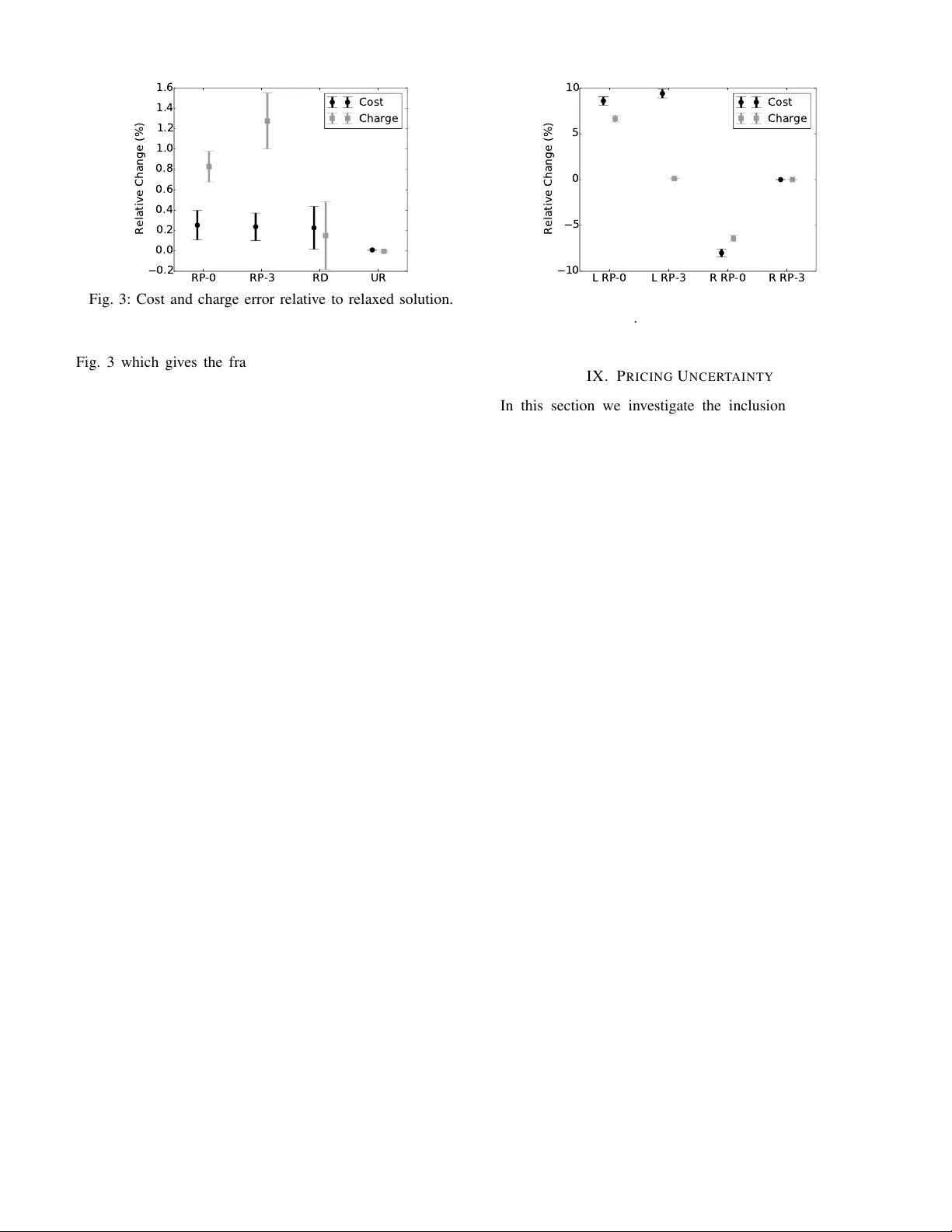
1 Dynamic Optimal Po wer Flo w in Microgrids using the Alternating Direction Method of Multipliers Paul Scott and Sylvie Thi ´ ebaux Abstract —Smart devices, storage and other distributed tech- nologies hav e the potential to greatly impro ve the utilisation of network infrastructure and renewable generation. Decentralised control of these technologies overcomes many scalability and privacy concerns, but in general still requir es the underlying problem to be conv ex in order to guarantee con vergence to a global optimum. Considering that A C power flows ar e non-conv ex in nature, and the operation of household de vices often requir es discrete decisions, ther e has been uncertainty surrounding the use of distrib uted methods in a r ealistic setting . This paper extends prior work on the alternating direction method of multipliers (ADMM) for solving the dynamic optimal power flow (D-OPF) problem. W e utilise more realistic line and load models, and introduce a two-stage approach to managing discrete decisions and uncertainty . Our experiments on a suburb-sized microgrid show that this approach provides near optimal results, in a time that is fast enough for r eceding horizon control. This work brings distributed control of smart-grid technologies closer to reality . Index T erms —OPF , ADMM, demand response, distributed control, microgrid I . I N T RO D U C T I O N T HE role of electricity market operators is to supply low cost and reliable electricity to customers. This typically in volves solving unit commitment (UC) and/or optimal po wer flow (OPF) problems at regular intervals. In the classical form of these problems, loads are assumed to be inflexible, so only large generators and network components need to be considered. Howe ver , this assumption will no longer hold true when smart de vices, distributed generation, storage, and electric vehicles (EVs) are adopted on mass. The traditional centralised market approaches were not designed to either operate where every consumer is an activ e participant, or handle their unique time-coupled behaviours. In order to manage this huge increase in problem size, sev eral works [1], [2], [3] hav e adopted distributed solving techniques. In addition to greatly parallelising the problem, these distributed algorithms help to preserve the priv acy of participants. These algorithms require the problem to be con- ve x in order to guarantee conv ergence to a globally optimal solution. Howe ver , the beha viour of many loads at a household lev el are discrete in nature [4], and the equations that govern how power physically flows on the network are non-conv ex. This paper considers the task of balancing po wer within a microgrid. W e formulate the problem as a dynamic optimal This work has been submitted to the IEEE for possible publication. Copyright may be transferred without notice, after which this version may no longer be accessible. The authors are from the College of Engineering and Computer Science at the Australian National University and the Optimisation Research Group at NICT A. power flow (D-OPF) problem to account for multiple time steps over a day , and solve it in a distributed manner by adopt- ing the alternating direction method of multipliers (ADMM) approach presented in [1]. W e extend the method to more accurate power flow models and introduce a two-stage pricing mechanism to manage integer variables and uncertainty . W e find that this approach achie ves near optimal solutions in a time frame that is fast enough to work with receding horizon control. This brings the overall approach closer to the point where it can be deployed on a real network. The introductory sections II-VI of this paper cover related work, our network model, the ADMM method and describe our test microgrid. This is followed by three sections VII-IX that focus on each of our contributions. I I . R E L A T E D W O R K Demand response (DR) is the name often gi ven to the control of distributed technologies. Much of the existing work on DR has focused on using real-time pricing (R TP) as a control signal [5], [6], [7], [8]. In these methods, participants receiv e a R TP signal and individually optimise their o wn behaviour , so as to minimise a combination of monetary and discomfort costs. Other approaches ha ve utilised non- pricing control signals, which are simpler to implement, but are limited in the types of loads that they can model [9], [10]. These approaches can be thought of as a form of open loop control, because the agent that sets the control signal (R TP or otherwise), at best can only estimate how consumers will respond to it. The work in [2] takes the idea of R TP and closes the loop. The R TP is iterativ ely updated by a central agent, with consumers communicating their best responses to the price before implementing them. An alternativ e iterative procedure is introduced in [3], where consumers cooperate to reduce total generation costs in a distributed manner . This approach is robust to gaming, but individual households only hav e a small incenti ve to change their habits, as their costs are largely independent of their own behaviour . The approaches discussed so far do not model the electricity network, so cannot account for real po wer losses, reactive power , voltage limits and line thermal limits. Most of the work on distributed algorithms that do model the network hav e used ADMM as a solving technique, due to its ease in decom- position, and its con ver gence guarantees on a wide range of problems [11]. One of the first authors to apply ADMM to power networks was Kim et al. [12]. They decomposed an OPF problem into regions and compared ADMM to two other approaches. They found that ADMM provided significant 2 T er minal Connec tion Bus Gen Ld Line Gen Gen Gen Bus Component Fig. 1: Con version to component orientated representation. speed impro vements over a centralised approach, and that priv acy is preserved between regions. In [13], Phan et al. used ADMM to improv e the parallel solve time for a security- constrained OPF (SCOPF) problem. They decomposed across scenarios and found it to hav e comparable solve times to a Bender’ s cut approach in many instances. The decomposition power of ADMM was taken one step further when Kraning et al. [1] decomposed all network components for a D-OPF problem. This is effecti vely a prin- cipled method for settling R TPs for each bus, also known as locational marginal prices. Their experiments showed that very large problems could be solved efficiently in a parallel en vironment. In this paper we extend this work to include more sophisticated line models, and a method for managing discrete variables and uncertainty , thereby making ADMM a practical approach to modern D-OPF problems. I I I . N E T WO R K M O D E L The overall objectiv e is to minimise the cost of supplying electricity . W e formulate this as D-OPF problems embed- ded within a receding horizon control process, in order to accurately control time-coupled components in an uncertain en vironment. In receding horizon control, a D-OPF is first solved over a horizon of n ∈ N time steps, the decision in the first step is acted on, and then the process repeats with the window shifted forward by one. In this paper we focus on solving the D-OPF within a single horizon, and the actions that agents take to implement the first decision. W e formalise the network model with this problem in mind. Note that the notation and formulation that we use is different from what is standard in power systems. This is necessary in order to decompose the network and distrib ute the problem. Fig. 1 highlights the difference between a standard line diagram and our formulation. A network N consists of a set of components C , terminals T and connections L . Each component c ∈ C (e.g., bus, line, generator , load) has a set of terminals T c ⊆ T which can be connected to the terminals of other components, where the T c sets partition T . Each connection l ∈ L is a pair of terminals, i.e. L ⊆ T × T . A. Connections A terminal represents a point of connection for an electrical component. W e use the quantities of real power , reactiv e power , voltage and voltage phase angle ( p, q , v , θ ∈ R n respectiv ely) to model the flow of po wer into a component through a terminal. These are vectors in order to capture each time step in the horizon. For conv enience we use a parent vector y i ∈ R 4 n to represent all variables for a terminal i ∈ T , where y i := ( p i , q i , v i , θ i ) T . When two terminals are connected together , ( i, j ) ∈ L , we pose the following constraints: p i + p j = 0 , q i + q j = 0 , v i − v j = 0 , θ i − θ j = 0 The first two constraints ensure the power that leaves one terminal enters the terminal it connects to. The second two constraints ensure that the terminals hav e the same voltage and phase angle. This duplication of variables is necessary in order to decompose the problem for the ADMM algorithm. T o av oid confusion, recall that connections and terminals are different from lines and buses (see Fig. 1). W e rewrite these constraints as y i + Ay j = 0 for y , where A is the appropriate 4 n × 4 n diagonal matrix. Further, we define the function h : R 4 n × R 4 n 7→ R 4 n as the LHS of this constraint for con venience: h ( y i , y j ) := y i + Ay j . B. Components At a high lev el, each component c ∈ C has a v ariable vector x c ∈ R a c , an objectiv e function f c : R a c 7→ R , and a constraint function g c : R a c 7→ R b c , where g c ( x c ) ≤ 0 . For a component c ∈ C , the vector x c includes all terminal variables for that component: y i , ∀ i ∈ T c . In the following sections we describe at a lower level the models for a variety of components. When necessary we use t ∈ { 0 , . . . , n } to index vectors by time, otherwise we imply standard vector operations. The index where t = 0 is used to represent the v alue of the v ariable at the beginning of the current horizon, which we assume is known. 1) Bus: A bus has a variable number of terminals which depends on how many other components connect to it. For example, a bus might be connected to a generator, a load and 3 lines for a total of 5 terminals. Regardless of the number of terminals, the constraints take the form: X i ∈ T c p i = 0 X i ∈ T c q i = 0 ∀ i, j ∈ T c : v i = v j , θ i = θ j The first two constraints are an expression of Kirchhof f ’ s current law (KCL) in terms of power flows. The remaining constraints ensure that all terminal voltages and phase angles are the same. 2) Line: A line is a two terminal component which trans- ports power from one location to another, typically from bus to bus. W e model a line as having a constant conductance g ∈ R + , susceptance b ∈ R and maximum apparent po wer s ∈ R + . The A C power flow equations are deri ved from Ohm’ s law , where ∀ i, j ∈ T c , i 6 = j : p i = g v 2 i − g v i v j cos( θ i − θ j ) − bv i v j sin( θ i − θ j ) (1) q i = − bv 2 i + bv i v j cos( θ i − θ j ) − g v i v j sin( θ i − θ j ) (2) s 2 ≥ p 2 i + q 2 i , v ≤ v i ≤ ¯ v , θ i − θ j ≤ ¯ θ (3) These constraints are identical for each time step, so we hav e left out the indexing by time to improv e clarity . These equa- tions are non-conv ex, so they are often either approximated or relaxed, as we will discuss further in Section VII. 3 3) Generator: A generator is a single terminal component which produces real and reactive po wer . In our formulation the generator has a floating phase angle and voltage. A generator has lower and upper real and reactiv e po wer limits such that p i,t ∈ [ p, ¯ p ] and q i,t ∈ [ q , ¯ q ] , a ramping rate p r ∈ R + and a quadratic cost function f for generation costs: f ( x ) = p T i Ψ p i − ψ T p i ∀ t ∈ { 1 , . . . , n } : − p r ≤ p i,t − p i,t − 1 ≤ p r where Ψ ∈ R n × n + is a diagonal matrix and ψ ∈ R n + . 4) Shiftable Load: A shiftable load is a single terminal component used to model electrical loads like dish washers and clothes dryers. These loads must start running between an earliest and a latest start time: t e , t l ∈ N . T o model this we introduce binary v ariables u ∈ { 0 , 1 } n for the horizon. A value of 1 indicates that the component starts at the given time. A component runs for a duration of d ∈ N consecutive time steps, during which it consumes a load of p nom ∈ R . p i,t = p nom t X t 0 = t − d +1 u t 0 t l X t = t e u t = 1 ∀ t 6∈ { t e , . . . , t l } : u t = 0 A con vex relaxation of this component can be obtained by relaxing the integrality requirement: u ∈ [0 , 1] n . 5) Battery: A battery is a single terminal component with stored energy E ∈ [0 , ¯ E ] n . The charge p c ∈ R n + and discharge p d ∈ R n + variables transfer energy to/from the battery: E t = E t − 1 + η p c t − p d t , E n ≥ ¯ E / 2 where the constant η ∈ [0 , 1] giv es the efficienc y of the battery and the net power into the component is giv en by p i = p c − p d . The second constraint above prev ents a greedy discharge of power at the end of the horizon. I V . A LT E R NA T I N G D I R E C T I O N M E T H O D O F M U LT I P L I E R S The goal is to minimise the sum of all component cost functions, subject to component and terminal connection con- straints. This is a utilitarian view of the problem. min x X c ∈ C f c ( x c ) s.t. ∀ c ∈ C : g c ( x c ) ≤ 0 ∀ ( i, j ) ∈ L : h ( y i , y j ) = 0 The augmented Lagrangian applied to the connection con- straints is giv en by: L ( L, y , z , λ, ρ ) := X c ∈ C f c ( x c ) + X ( i,j ) ∈ L h ρ 2 k h ( y i , z j ) k 2 2 + λ T i,j h ( y i , z j ) i where ρ ∈ (0 , ∞ ) is a penalty parameter and λ i,j ∈ R 4 n are the dual variables for the connection constraints. The dual variables also represent the locational marginal prices in our problem. The alternating direction method of multipliers (ADMM) is a variation of the standard augmented Lagrangian method that enables problem decomposition [11], [14], [15]. A single iteration consists of two phases followed by a dual variable update. Components are each allocated to one of the two phases. The component sets C 1 and C 2 , and the variable vectors x 1 and x 2 represent this allocation. The connections are split into three parts: L 1 , L 2 and L 1 , 2 . The intra-phase connections L 1 ( L 2 ) are those that are between components in C 1 ( C 2 ). The inter-phase connections L 1 , 2 are those where one component is in C 1 and the other is in C 2 . The superscript k ∈ N is used to indicate the k -th iteration. At the start of the algorithm all terminal and dual variables are initialised to some values y (0) i and λ (0) i,j . For the k -th iteration ADMM proceeds as follows: 1) Optimise for x 1 , holding x 2 constant at its k − 1 value 2) Optimise for x 2 , holding x 1 constant at its k value 3) Update the dual variables λ For our optimisation problem this becomes: x ( k ) 1 = arg min x 1 L ( L 1 , 2 , y , y ( k − 1) , λ ( k − 1) , ρ k ) (4) s.t. ∀ c ∈ C 1 : g c ( x c ) ≤ 0 ∀ ( i, j ) ∈ L 1 : h ( y i , y j ) = 0 x ( k ) 2 = arg min x 2 L ( L 1 , 2 , y ( k ) , y , λ ( k − 1) , ρ k ) (5) s.t. ∀ c ∈ C 2 : g c ( x c ) ≤ 0 ∀ ( i, j ) ∈ L 2 : h ( y i , y j ) = 0 ∀ ( i, j ) ∈ L 1 , 2 : λ ( k ) i,j = λ ( k − 1) i,j + ρ ( k ) h ( y ( k ) i , y ( k ) j ) (6) In the simple case when ρ is constant, f c and g c are conv ex, and h is affine, ADMM con ver ges to a global optimum [11]. If a component has no intra-phase connections, then its sub- problem can be solved independently of all other components in the same phase. W e adopt the partitioning scheme where C 2 contains all buses and C 1 the rest of the network. This allows us to fully separate all components, since buses will nev er connect to other buses ( L 2 = ∅ ) and non-bus components will nev er connect to other non-bus components ( L 1 = ∅ ). As an additional benefit, some components are simple enough that we can analytically calculate the solution to their subproblem at each iteration, instead of in voking an optimisation routine. W e adopt such an analytical approach for buses as proposed in [1]. Other partitioning schemes are discussed in Section VII. A. Residuals and Stopping Criteria As in [1], we use primal and dual residuals to define the stopping criteria for our algorithm. The primal residuals represent the constraint violations at the current solution. W e combine the residuals of all connections into a single vector r p . By indexing into the inter-phase connections L 1 , 2 = { ( i 1 , j 1 ) , ( i 2 , j 2 ) , . . . } , the primal residual is giv en by: r ( k ) p := ( h ( y ( k ) i 1 , y ( k ) j 1 ) , h ( y ( k ) i 2 , y ( k ) j 2 ) , . . . ) T The dual residuals give the violation of the KKT stationarity constraint at the current solution. W e collect the dual residuals 4 for each each connection into the vector r d . For ADMM, the dual residuals are given by (see [11] for deriv ation): r ( k ) d := ( λ ( k ) i 1 ,j 1 − λ ( k − 1) i 1 ,j 1 , λ ( k ) i 2 ,j 2 − λ ( k − 1) i 2 ,j 2 , . . . ) T These residuals approach zero as the algorithm con verges to a KKT point. W e consider that the algorithm has con verged when the scaled 2 -norms of these residuals are smaller than a tolerance : 1 √ M k r ( k ) p k 2 < , 1 √ M k r ( k ) d k 2 < . Here M is the total number of inter -phase terminal constraints 4 n | L 1 , 2 | minus the number of terminal constraints that are trivially satisfied (e.g., floating voltages and phase angles for generators). It is used to keep the tolerance independent of problem size. V . I M P L E M E N TA T I O N W e dev eloped an experimental implementation of the ADMM method in C++ using Gurobi [16] and Ipopt [17], [18] as backend solvers. Gurobi is used for mixed-integer linear or quadratically constrained problems, and Ipopt for more general nonlinear problems. CasADi [19] was used as a modelling and automatic differentiation front end to Ipopt. This implementation was designed with flexibility in mind, so that a wide range of experiments could be conducted. For a more specialised and performance orientated implementation see [1]. Although this is a sequential implementation of the ADMM method, we timed the slowest component at each iteration to get an idea of ho w long a fully distributed implementation would take. The experiments were run on machines with 2 AMD 6-Core Opteron 4184, 2.8GHz, 3M L2/6M L3 Cache CPUs and 64GB of memory . V I . T E S T M I C RO G R I D The distributed algorithm we have presented can be used to control all levels of the electricity system, potentially in a hi- erarchical manner [1]. W e focus our attention on a microgrid- like distribution network since that is where we expect to hav e the greatest impact with the adoption of distributed generation and storage. Our experiments are based around a modified 70 bus 11kV benchmark distrib ution network [20], which was chosen due to its comparable size to a suburb . W e close all tie lines in the network in order to change it from a radial to a meshed configuration. This is because we expect microgrids to take on more of a meshed network structure to improve reliability , efficienc y and to better utilise distributed generation. The benchmark comes with a static PQ load at each bus, which we replace with a number of houses, depending on the size of the load. The houses are connected directly to the 11kV buses as we have no data on the low voltage part of the network. W e assume that the power bounds we place on each household will be sufficient to prev ent any capacity violation of the low voltage network. A house is an independent agent that manages subcom- ponents. These include an uncontrollable background power draw , two shiftable loads, and optional battery and solar PV systems. A house has a single terminal through which it can T ABLE I: Component parameters. Component Param V alue Units Generator ψ t ∼ max(4 , N (40 , 8 2 )) $/MWh Generator Ψ t,t ∼ max(1 , N (10 , 2 2 )) $/MWhMW Generator p, ¯ p − s × h/ 2 , 0 kW Generator q , ¯ q 0 . 2 p, − 0 . 2 p kvar House p t ∼ N ( l t , (0 . 2 l t ) 2 ) kW House q t 0 . 3 p t kvar Shift 1 d ∼ max(15 , N (90 , 18 2 )) min Shift 1 p nom ∼ max(0 . 3 , N (3 , 0 . 6 2 )) kW Shift 2 d ∼ max(15 , N (60 , 12 2 )) min Shift 2 p nom ∼ max(0 . 1 , N (1 , 0 . 2 2 )) kW Shift t e , t l 0 , n − d exchange real and reacti ve power with the rest of the network. Each house has an apparent power limit of s = 10 kV A. W e dev elop a typical house load profile l t by modifying an aggregate Autumn load profile for the A CT region in Australia (data from [21]). W e assume that households consume on av erage 20kWh per day . This provides the basis for all uncontrollable household background loads. For the purposes of these experiments, we assume that the static PQ loads in the benchmark were recorded when loads were at 75% of their peak. W e divide the benchmark static real power at each bus by how much power a typical house consumes at 75% of its peak power (1.45kW). Rounding do wn this number giv es us an estimate of the number of houses which would be located at a giv en bus. This approach produces a total of h = 3674 houses for the network, about the size of an Australian suburb . W e place two generators in the network where the distri- bution system connects to upstream substations. These can be thought of as either dispatchable microgenerators or as representing the cost of importing power into the microgrid. W e randomise some of the generator and household load parameters to produce different problem instances, as can be seen in T able I. The time horizon spans 24 hours with 15 minute time steps, which produces a problem instance with ov er 2 million v ariables per horizon. The experiments were run with a primal and dual stopping tolerance of = 10 − 4 and a fixed penalty parameter of ρ = 0 . 5 . T o improve numerical stability , we scale the system to a per-unit representation with base v alues at 11kV and 100kV A. This means that a real po wer residual of 10 − 4 translates to 10W for a connection, or about 1% of the average household load. In addition to the 70 bus network described here, we also ran a series of experiments on randomly generated networks similar to those described in [1]. These randomly generated networks ranged in size from 20 to 2000 buses, and were designed to be highly congested. W e will occasionally mention some of the results from these random networks when they differ from our 70 bus microgrid. V I I . I M P A C T O F P O W E R F L OW M O D E L S In this section we in vestigate ho w the ADMM method performs with different power flow models. W e assess 4 alternativ e models to the one presented in [1], all of which giv e more accurate results, but are slower to con verge. 5 A. P ower Flow Models Due to their non-con vex nature, the AC power flow equa- tions (1 – 3) are often either relaxed or approximated. Conv ex relaxations include a quadratic constraint (QC) model [22], a semi-definite program [23], the dist-flow (DF) relaxation [24], [25] and an equiv alent SOCP relaxation [26], [27]. Approximations include the linear DC (DC) model [28], [29], the LP AC model [30] and the equations proposed by Kraning et al. (K) [1]. These alternativ e models are often used to solve difficult power network optimisation problems, for example, OPF , OPF with line switching, capacitor placement and expansion planing. ADMM was used with the DF model in [31] in order to control the reactiv e po wer of inv erters on a radial network, and the K model was used with ADMM in [1] to solve the D-OPF problem. What is lacking is an understanding of the relati ve strengths and weaknesses of line models when used in a distributed algorithm. In this section we compare how the distributed ADMM algorithm performs when using the A C, QC, DF , DC, and K line models. W e compare the dif ferences in solution quality , feasibility , processing time and number of iterations for our test network. B. Experiments W e generated 60 instances of our test network with the bi- nary variables for the shiftable devices relaxed. T o ev aluate the quality of the solutions we calculate the percentage dif ference in objectiv e value relativ e to the best known AC solution: 100 · ( f − f best ) /f best . The means and standard de viations of the 60 instances are: QC -0.031% (0.008%) DF 0.039% (0.018%) DC -3.541% (0.072%) K 4.726% (0.090%) W e don’t have a guarantee that the A C solution is optimal because the equations are non-conv ex. Ho we ver , the relaxed models (QC, DF) provide a lo wer bound on the global optimum, allowing us to identify in the worst case how far the A C solution is from optimality . The DF model produces results that are slightly above the A C model, when it should be providing a lower bound. This is because the result is within the margin of error for our stopping criteria, which we estimated to be 1%. By decreasing we found the positiv e difference to shrink further into insignificance. Based on our results the optimality gap is tiny for both the QC and DF models. These results give us confidence that the non-con vex A C model, which is the only one that guarantees Ohm’ s law is satisfied, produces solutions that are very close to optimal. Other work has come to a similar conclusion in a dif ferent setting [22], [13]. The DC model underestimates the optimal value by around 3.5% while the K model overestimates it by around 4.7%. Part of the reason for this is that the DC model ignores line losses and the K model is overestimating line losses. T able II provides the number of iterations and time taken to con verge in the form of means and standard de viations. The parallel solve time is the amount of time required to solve the problem in a fully distributed implementation. This was T ABLE II: Iterations and parallel solve time for line models. Iterations (std.) T ime in sec (std.) A C 1945 (17) 148 (12) QC 1951 (14) 546 (33) DF 1933 (26) 110 (8) DC 4140 (50) 244 (8) K 1027 (52) 15 (1) 0 1000 2000 3000 4000 Iteration 1 0 - 4 1 0 - 3 1 0 - 2 Residual AC QC DF DC K Fig. 2: Con ver gence of primal residuals. measured by summing together the time of the slowest com- ponent at each iteration. In absolute terms the parallel solve time is relati vely small despite the f act that our implementation was designed with flexibility in mind, not performance. That said the K model is significantly faster relati ve to the other models. It con verges in half the number of iterations required by the next fastest model, but as we hav e seen it gives us an inaccurate result. The highly congested random networks that we generated produce similar results. Howe ver , for a number of instances the K model was infeasible (would not con ver ge) where we had a valid A C solution, due to the exaggeration of line losses. Fig. 2 shows an example of the primal residual con ver gence for different line models (the dual residuals are similar). The A C, QC and DF models overlap. One unintuitive result is the fact that the DC model con ver ges poorly when it is in fact a very simple linear model. Large oscillations build up during the solution process which slows the rate of con ver gence. W e performed a series of experiments in order to get a better understanding of this effect. The best explanation we hav e is that the DC model behav es like an undamped system, as it has no line losses and only linear constraints. The DC model will respond stronger for a given change in its terminal dual variables. The net effect is that oscillations build up across the network during the solving process. On the other hand the K model overestimates line losses, which means it is much less sensitiv e and no oscillations form. The AC, QC and DF models are somewhere in between these two extremes. In reality communication delay will play a major part in the total solve time for the algorithm. For example, if we assume that it takes 60ms to communicate messages on our network (which happens a minimum of two times per iteration), then 1000 iterations would require 2 minutes of communication time. In certain circumstances it may be beneficial to cut down the total number of iterations, ev en if it requires more 6 processing time per iteration. W e experimented with clustering some lines and buses together instead of fully decomposing the network. The idea is that, depending on the communication delay , this could reduce overall solve time by solving more of the problem at once. This was clearly beneficial for the random networks, but for the 70 bus microgrid the results so far are inconclusiv e. For example, clustering the 70 b us network into 16 parts halved the number of iterations required, but the overall solve time worsened. W e expect this to change once we start to optimise our implementation, by reducing solver ov erhead and decomposing network components across time steps. It is important to point out that we are giving the algorithm a naiv e starting point for both the primal and dual variables. In practice, the receding horizon control scheme will provide an excellent warm starting point, because the values from the previous horizon can be used for all but one time step. As a sanity check, we performed warm starting experiments for the A C model. Similar to what was done in [1], we duplicate a problem instance and then randomly resample the household background po wer and shiftable de vice power parameters according to the rule: p ∼ p N (1 , σ 2 ) . W e used the solution of the original instance as a starting point for the modified instance. For σ = 0 . 2 the warm started run only needed 11% of the original iterations on av erage. In a second experiment we fully correlated the resampling step, which could represent a correlated change in solar panel output for many households. W ith σ = 0 . 2 , only 29% of the original iterations were required on av erage. These results show the feasibility of using the non-con ve x A C power flow equations for solving a distributed D-OPF problem. The K model con ver ges much faster , but it is unlikely to be usable in a realistic setting, as it ignores voltages and reactiv e power , and produces ov erly high costs. For these rea- sons, we adopt the AC model for the rest of our experiments. V I I I . D I S C R E T E D E C I S I O N S W e now e xtend the algorithm so that it can deal with discrete decisions. Components with discrete decisions are be common in realistic household models and they are required to model more complicated generators and network switching ev ents. W e develop a framework that can accommodate discrete variables otherwise we could risk network violations through unpredictable household behaviour . A. Methods W e in vestigate three tractable methods for dealing with integer variables which have no global optimality guarantees. Just as we did for the A C equations, we will compare our result to a lower bound in order to get an understanding of the optimality gap. W e categorise these methods as: • Relax and price (RP) • Relax and decide (RD) • Unrelaxed (UR) The RP and RD approaches are broken up into two stages. The first stage, also kno wn as the negotiation stage, is common to both methods. Here all integer v ariables are relaxed and the distributed algorithm is run until con ver gence. At this point the integer variables may take on fractional values, and this solution giv es a lower bound on the optimal. In the second stage each component makes a local decision in order to force any fractional values to integers. Recall from Section III-B4 that shiftable devices have a binary variable u t for each time step, only one of which can take on the value 1 to indicate the starting time. In the second stage of the RP method, each house performs a local optimisation to determine ho w to enforce integer feasibility of u t . W e designed a range of cost functions which penalise a component if it changes its terminal values from those nego- tiated. For a giv en cost function each house solves a Mixed- Integer Program (MIP) to obtain an integer -feasible solution. The two most effecti ve cost functions that we identified are: f 0 ( y , ˆ y , ˆ λ ) = ˆ λ T y + αh ( y , ˆ y ) T h ( y , ˆ y ) (7) f 3 ( y , ˆ y , ˆ λ ) = ˆ λ T A ˆ y + α h ( y, ˆ y ) T Λ h ( y , ˆ y ) (8) Where for a given house to bus connection ˆ y is the negotiated terminal values for the bus and ˆ λ the negotiated dual v ariables. W e use Λ to represent the diagonal matrix where Λ i,i := | ˆ λ i | and α is a penalty parameter . The first function charges households at the negotiated price for what they actually consume, but they are also charged a quadratic penalty for operating away from the negotiated consumption. The second function requires the household to pay for all power that was negotiated in the first stage. Like the first function a penalty is charged for operating away from the negotiated operating point, ho wev er the penalty is scaled by the dual variables which can vary with time. After this local optimisation step, we check that the solution is feasible and what the overall cost is. In order to do this we need to put some degrees of freedom back into the problem. In power networks the dispatch of generators are established in advance in response to an estimated demand. This forecast is nev er perfect, so a certain number of generators are paid to perform frequency regulation in order to balance demand in real time. In our experiments we employ both our generators for this use by allowing them to adjust their output. For these experiments we assume the same cost function and prices for both dispatch and frequency regulation. In the second stage of the RD method, the largest u t value of each shiftable component is chosen to be fixed at 1 and the rest set to 0. After this is done the distributed algorithm is started again in order to con ver ge to a new solution that is integer feasible. The final approach, UR, attempts to enforce integrality satisfaction at each iteration of the distributed algorithm. W e have already foregone theoretical con vergence guarantees by our adoption of the non-con vex AC equations. Here we push the ADMM algorithm ev en further by allowing discrete variables into the algorithm (4 – 6), where Gurobi solves MIPs for houses, and Ipopt NLPs for lines. B. Experiments W e ran experiments on 60 random instances of our test network with a penalty of α = 10 . The results can be seen in 7 RP-0 RP-3 RD UR 0.2 0.0 0.2 0.4 0.6 0.8 1.0 1.2 1.4 1.6 Relative Change (%) Cost Charge Fig. 3: Cost and charge error relativ e to relaxed solution. Fig. 3 which gi ves the fractional change with respect to the relaxed problem. This is shown both in terms of the cost of generation and the char ge to households. The charge is the sum of household objectiv e functions, which represents the amount of money they pay for their electricity . For the RP methods this is giv en by the cost functions in the previous section. For the RD and UR methods the charge is simply the final λ T y for each house. For the relaxed problem itself, the true cost of generation can be dif ferent from the amount households are charged, as we are dealing with marginal prices. In addition to this, network congestion typically generates additional revenue abov e the cost of generation itself. An increase in cost for the integer feasible solution relative to the relaxed problem is an indication of the additional cost to the generators for balancing supply . Where household charge has increased relativ e to the relaxed solution, then households have decided to take on additional costs in order to change their consumption. All methods produce costs that are within 1% of the relaxed problem. There is no significant dif ference between the four methods as they reside within our estimated margin of error based on our stopping tolerance. What these results suggest is that we ha ve a tight relaxation of the integer problem. From other experiments, the relaxation of the shiftable devices is tight except where we have a heavily congested system. This combined with the fact that each shiftable load only contributes a tiny amount to the ov erall power demand giv es us a tight relaxation. The RP method only marginally increases solve time abov e the results in the Section VII. The RD method requires some of extra time as it performs a warm restart of the distributed algorithm. The UR method took 1.7 times longer on av erage as it solves MIPs during each iteration. The charges to households are significantly higher for the RP method without gaining any benefit in terms of reduced costs. W e ran the same experiments with a much smaller α which all b ut eliminated char ges, without an y increase to costs. This suggests that for the sole purpose of managing discrete decisions, there is no need to have a strong penalty . All of the methods we hav e presented provide an efficient means for dealing with the discrete decisions in a household. Howe ver , we will come to see in the next section why we fa vour the RP approach. L RP-0 L RP-3 R RP-0 R RP-3 10 5 0 5 10 Relative Change (%) Cost Charge Fig. 4: Performance of cost functions with lowering (L) and raising (R) solar output. I X . P R I C I N G U N C E RT A I N T Y In this section we in vestigate the inclusion of stochastic components into our system. Many parameters such as back- ground household power consumption, solar PV output can only be estimated. This means that the solutions that are negotiated through our distributed mechanism may not be applicable when it comes time to act. For example, if the output of household solar PV systems is lower than expected, then certain lines in the network could be overloaded if the network was already running near capacity . Part of the way of dealing with this is to run receding horizon control so that we only e ver act on the most immediate time step before reoptimising. Howe ver even within the most immediate time step we still hav e to deal with uncertainty . In this section we use the RP method from the previous section to encourage households to correct for any local sources of uncertainty . Of the three methods designed to handle discrete variables, this is the only one that can provide this type of incentiv e. T o simplify the experiments we don’t perform full receding horizon control. W ith receding horizon control we expect the same trends, but with further improvement to costs. A. Experiments W e perform a simple experiment on the 70 bus microgrid where we have added 2kW PV systems and 2kWh batteries independently and at random to half of the houses. The battery ef ficiencies η were uniformly sampled from the interv al [0 . 85 , 0 . 95] . For normalised solar irradiance we use the simple relation: I t = max(0 , sin(2 π t/ 96 − π / 2)) . W e solve the first of the RP method with this irradiance, and then either lower or raise it it 20% before running the second stage. Fig. 4 shows the resulting costs and charges relativ e to the first stage result. Lowering solar output produces increases to generation costs of between 8-10% relativ e to the original solution. Function 0 performs around 1% better on a verage and it increases the charge to the house in line with the increased generation costs. For function 3 the households are barely penalised for this increase in generation costs. When solar output is raised function 3 doesn’t react at all because it has no incentiv e to. Function 0 on the other hand takes adv antage of the excess solar to lower ov erall costs by around 8%. 8 As we found in the previous section, generator costs are relativ ely independent of the RP cost function penalty param- eter α . Howe ver , α can be used to increase household charges. This means that α can be tuned ov er time to ensure that the market is budget balanced. For example, these extra penalties can be used to recov er frequency regulation costs or to help pay for fixed network costs. Larger penalties could also help to deter agents looking to game the system. In the current mechanism, there is nothing that prev ents an agent from misreporting their behaviour during the negotiation phase. A larger penalty forces them to act on what they ne gotiated, so can significantly limit this beha viour . The problem is that it will be difficult to distinguish between someone looking to cheat the system, and someone with a large amount of local uncertainty or discrete loads. This makes it difficult to penalise one of these effects without penalising the others. Houses with batteries hav e more flexibility in ho w the y can deal with local sources of uncertainty , so a system with batteries and reasonable penalties might provide the best compromise. X . C O N C L U S I O N A N D F U T U R E W O R K W e ha ve improv ed on existing distributed ADMM based D-OPF methods by including more accurate line models and a two-stage approach to manage discrete variables and uncertainty . W e developed a suburb sized test microgrid, and found that the full non-conv ex A C equations produce close to optimal solutions in short solve times. Our two-stage approach provides a simple but ef fectiv e means of managing household discrete variables and uncertainty in the network. Future research will focus on inv estigating alternative dis- tributed solving techniques with the aim of further improving con vergence. There are also opportunities to parallelise the problem more by decomposing some components across time. Further research needs to be done on the real-time control that takes place within and between time-steps, and it might be possible to build a frequency regulation market into our distributed algorithm. W e need further experiments to inv estigate if our results carry over to larger discrete decisions, for e xample, those related to large industrial plant, generator start-up costs, and line switching. W e also plan to answer the important question of ho w susceptible this mechanism is to gaming in practice, and if this is a problem, what can be done about it. R E F E R E N C E S [1] Kraning, M., Chu, E., Lav aei, J., Boyd, S.: Dynamic network energy management via proximal message passing. Foundations and Trends in Optimization 1 (2) (2014) [2] Gatsis, N., Giannakis, G.: Residential load control: Distributed schedul- ing and conv ergence with lost ami messages. Smart Grid, IEEE T ransactions on 3 (2) (June 2012) 770–786 [3] Mohsenian-Rad, A., W ong, V ., Jatskevich, J., Schober , R., Leon-Garcia, A.: Autonomous demand-side management based on game-theoretic energy consumption scheduling for the future smart grid. Smart Grid, IEEE T ransactions on 1 (3) (dec. 2010) 320 –331 [4] Ramchurn, S.D., Vytelingum, P ., Rogers, A., Jennings, N.R.: Agent- based control for decentralised demand side management in the smart grid. In Tumer , Y olum, Sonenberg, Stone, eds.: Proc. of 10th Int. Conf. on Autonomous Agents and Multiagent Systems - Innov ativ e Applications T rack (AAMAS 2011), T aipei, T aiwan (May 2011) 330– 331 [5] Mohsenian-Rad, A.H., Leon-Garcia, A.: Optimal residential load control with price prediction in real-time electricity pricing environments. Smart Grid, IEEE Transactions on 1 (2) (sept. 2010) 120 –133 [6] Chen, Z., W u, L., Fu, Y .: Real-time price-based demand response management for residential appliances via stochastic optimization and robust optimization. Smart Grid, IEEE Transactions on 3 (4) (dec. 2012) 1822 –1831 [7] Scott, P ., Thi ´ ebaux, S., van den Briel, M., V an Hentenryck, P .: Residen- tial demand response under uncertainty . In: International Conference on Principles and Practice of Constraint Programming (CP), Uppsala Sweden (sep. 2013) 645–660 [8] Tischer , H., V erbic, G.: T ow ards a smart home energy management system - a dynamic programming approach. In: Innovati ve Smart Grid T echnologies Asia (ISGT), 2011 IEEE PES. (nov . 2011) 1 –7 [9] van den Briel, M., Scott, P ., Thi ´ ebaux, S.: Randomized load control: A simple distributed approach for scheduling smart appliances. to appear in IJCAI 2013 (2013) [10] Shinwari, M., Y oussef, A., Hamouda, W .: A water-filling based schedul- ing algorithm for the smart grid. Smart Grid, IEEE T ransactions on 3 (2) (June 2012) 710–719 [11] Boyd, S., Parikh, N., Chu, E., Peleato, B., Eckstein, J.: Distributed optimization and statistical learning via the alternating direction method of multipliers. Foundations and T rends in Machine Learning 3 (1) (Jan 2011) 1–122 [12] Kim, B., Baldick, R.: A comparison of distributed optimal power flow algorithms. Power Systems, IEEE Transactions on 15 (2) (2000) 599–604 [13] Phan, D., Kalagnanam, J.: Some efficient optimization methods for solving the security-constrained optimal power flow problem. Power Systems, IEEE Transactions on 29 (2) (March 2014) 863–872 [14] Douglas, Jim, J., Rachford, H. H., J.: On the numerical solution of heat conduction problems in two and three space variables. Transactions of the American Mathematical Society 82 (2) (1956) pp. 421–439 [15] Gabay , D., Mercier, B.: A dual algorithm for the solution of nonlinear variational problems via finite element approximation. Computers & Mathematics with Applications 2 (1) (1976) 17 – 40 [16] Gurobi Optimization, Inc.: Gurobi optimizer reference manual (2014) [17] W ¨ achter , A., Biegler , L.T .: On the implementation of an interior- point filter line-search algorithm for large-scale nonlinear programming. Mathematical Programming 106 (1) (2006) 25–57 [18] HSL Archive: A collection of fortran codes for large scale scientific computation (2014) [19] Andersson, J.: A General-Purpose Software Framew ork for Dynamic Optimization. PhD thesis, Arenberg Doctoral School, KU Leuven, Department of Electrical Engineering (ESA T/SCD) and Optimization in Engineering Center, Kasteelpark Arenberg 10, 3001-Hev erlee, Belgium (October 2013) [20] Das, D.: Reconfiguration of distribution system using fuzzy multi- objectiv e approach. International Journal of Electrical Power & Energy Systems 28 (5) (2006) 331 – 338 [21] Australian Energy Market Operator (AEMO): www .aemo.com.au. [22] Hijazi, H.L., Coffrin, C., V an Hentenryck, P .: Conve x quadratic relax- ations for mixed-integer nonlinear programs in power systems. NICT A T echnical Report http://www .optimization- online.org/DB HTML/2013/ 09/4057.html (March 2014) [23] Bai, X., W ei, H., Fujisawa, K., W ang, Y .: Semidefinite programming for optimal power flow problems. International Journal of Electrical Power & Energy Systems 30 (67) (2008) 383 – 392 [24] Fariv ar, M., Clarke, C.R., Low , S.H., Chandy , K.M.: Inverter var control for distribution systems with renewables. In: SmartGridComm, IEEE (2011) 457–462 [25] Baran, M., W u, F .: Optimal sizing of capacitors placed on a radial distribution system. Power Delivery , IEEE Transactions on 4 (1) (1989) 735–743 [26] Jabr, R.: Radial distribution load flow using conic programming. IEEE T ransactions on Power Systems 21 (3) (Aug 2006) 1458–1459 [27] Bose, S., Low , S.H., T eeraratkul, T ., Hassibi, B.: Equival ent relaxations of optimal power flow . CoRR abs/1401.1876 (2014) [28] Schweppe, F ., Rom, D.: Po wer system static-state estimation, part ii: Approximate model. power apparatus and systems, IEEE transactions on (1) (1970) 125–130 [29] Stott, B., Jardim, J., Alsac, O.: Dc power flow revisited. Power Systems, IEEE T ransactions on 24 (3) (Aug 2009) 1290–1300 [30] Coffrin, C., Hentenryck, P .V .: A linear-programming approximation of ac power flows. Informs Journal on Computing (May 2014) [31] ˇ Sulc, P ., Backhaus, S., Chertkov, M.: Optimal Distributed Control of Reactiv e Power via the Alternating Direction Method of Multipliers. ArXiv e-prints (2014)
Original Paper
Loading high-quality paper...
Comments & Academic Discussion
Loading comments...
Leave a Comment