Acoustic Scene Analysis using Analog Spiking Neural Network
Sensor nodes in a wireless sensor network (WSN) for security surveillance applications should preferably be small, energy-efficient, and inexpensive with in-sensor computational abilities. An appropriate data processing scheme in the sensor node redu…
Authors: An, Kumar Mukhopadhyay, Naligala Moses Prabhakar
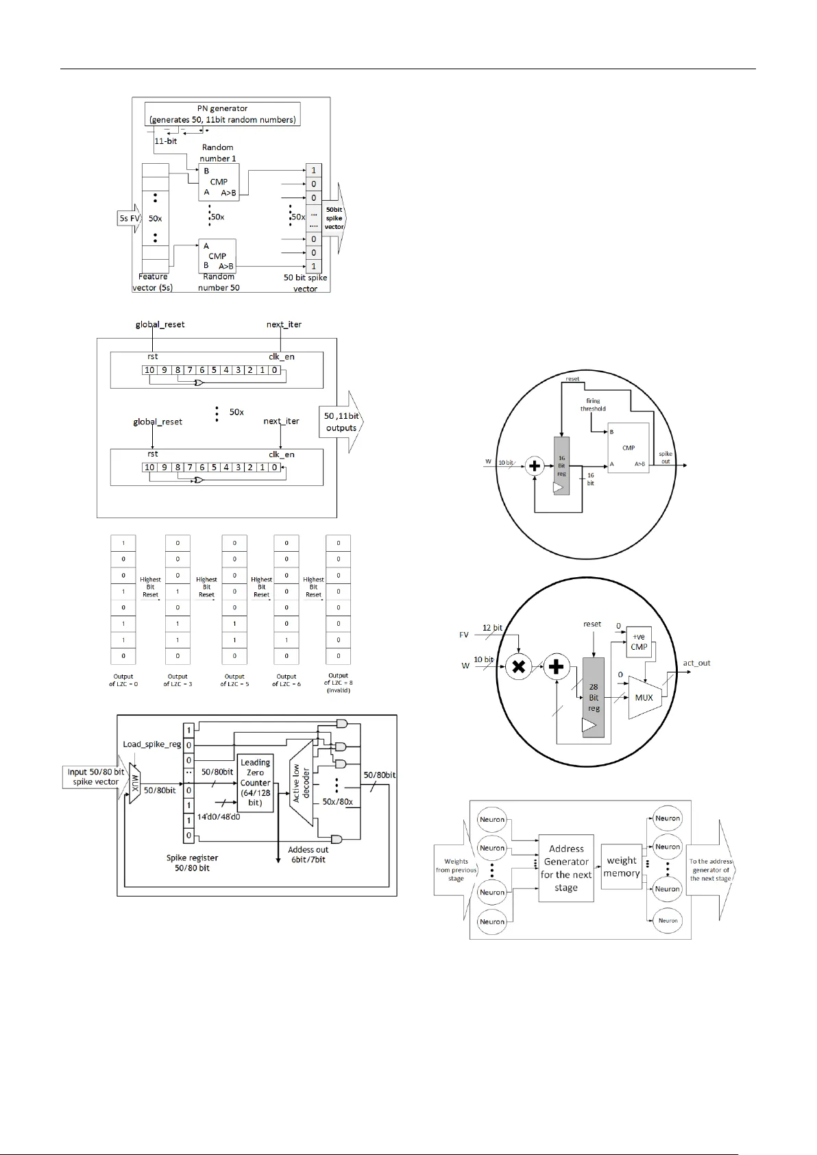
Acoustic Scene Analysis using Analog Spiking Neural Network Anand Kumar Mukhopad hyay, Nali gala Moses Prabhakar, Di vya Lakshmi Duggisett y, Indrajit Cha krabarti, and Mrigank Sharad Abstract Sensor nod es in a wireless sensor networ k (WSN) for secur ity surveillance applications should pr eferably be small, energy -efficien t, and inexpensive with in -sensor computational abilities. An appr opriate data processing scheme in the sensor node reduces the power dissipation of th e transceiver through the compression of informatio n to be communicated. This study attempted a simu lation-based analysis of human footstep sound classification in natural surroun dings using simple time -do main features. The spikin g neural network (SNN), a computationally low-weig ht classifier derived from an artificial neur al network (ANN) , was used to classify acoustic sounds. The SNN an d required feature ex traction schemes are amenable to low-power subthreshold analog implem entation. Th e results show th at all analog implementation s of the propo sed SNN scheme achieve significant power savings over the digital implemen tation of the same com puting scheme and o ther conventional digital architectures u sing frequency -domain fea ture extraction and ANN- based classification. The algorithm is tolerant of the impact o f process variation s, which ar e inevitab le in analog design, owin g to the approximate nature of the data processing involved in such applicatio ns. Although SNN provides low -power operatio n at the algorithm level itself, ANN to SNN conversion leads to an unavoid able loss of classification accuracy of ~5%. We ex ploit ed the low-power operation of the analog processing SNN modu le by applying redundan cy and majority vo ting, which improved the classification accuracy , taking it close to the ANN model. Keywords: Acoustic wireless sen sor nodes, security surveillance ap plication, spiking neural network, resistive crossbar network, energy efficiency 1. Introduc tion Wireless sensor networks (WSNs) have applicatio ns in a wide ran ge of h ealth care, environment, agriculture, public safety, military, ind ustry , and tran sportation systems [1 ]. The sensor nodes in a WSN are designed according to th e target application. Acoustic sensor nodes for a security surveillance application to monitor the presence of human b eings in restricted zones fall under the category of passive supervision , which senses the data around its environm ent and requires minimal power to operate . In general, small- sized static sensor nodes are d eployed in large numbers with continuous monitoring. Th ese resource -constrain ed sen sor nodes should be inexpensive an d power -efficient (few μ W) for serv ing the purpose [2]. One of the constraints that the wireless sensor no des suffer from is limited battery life. Th e most po wer-hungry component in a WSN is th e transceiv er u nit [2 , 3 ]. Hence, in- sensor computin g is applied in the sensor n odes to minimiz e the communication power due to compressed data transmission. The sensor nodes h aving in-sen sor computation al abilities should consume less energy, preferably much l ower than the transceiver unit. Therefore, there is a need f or a cross -hierarch y power-efficien t system design approach that spans the a pplication -specific computing system s alg orithm, architectur e, and circu it-level implementation . With the advancement in the field of energy -efficient brain-in spired neuro morphic compu ting algorithm s, sever al l ow -power comp uting systems hav e been envisaged and implemented , wh ich ar e suitable for in-sen sor compu ting and 2 data classificatio n [4 ][5][6][7][8][ 16][55][60] . Spiking neur al networks (SNNs), considered the 3 rd generation of neural network s [38], are inspired by biolog ical n eurons in which communication betwe en neurons take s place in the form of spikes (or events) through interconnecting 'weights' called synapses. Th e neuron membrane potential (v mem ) is affected based on its pr esynaptic events, i.e., because of the spikes generated by the preceding layer neurons. A post -synap tic spike is g enerated whenever v mem exceeds th e neuron 's threshold poten tial (v th ), and commu nicated to the nex t layer of neurons connected to it. Such bio- mimicking neural networks significantly reduce computational complexity, owing to even t-driven computing an d binary signal levels[39]. The learning rules for SNN algorithms can be supervised or u nsupervised, rate-based, o r spike- time b ased, which is chosen b ased on th e ap plication [9]. The primary motivation for in volving SNN in a real-time application involving energy-ef ficient neuromorphic hardwar e is to reduce the computation s involv ed in the system [ 55][62] . Generally, the computation s du ring the training of neu ral n etwork framework s are compute- intensive comp ared to the feedforward inference p rocess. Hence, offline training with online in ference is suitable for a static sen sor node and its associated classifier [40][57]. We have considered a method for train ing an ANN with the conven tional backpropagation algorithm to obtain the trained par ameters using a rate -based SNN f or classification [6]. This appro ach achieves acceptable classification perfor mance owing to offline supervised train ing with a more ex tensiv e data set an d low- power op eration due to lesser comp utations involved in the SNN-based classifier. In this wo rk, we present an integrated system design f or a low-power sensor node targeted for a surveillan ce application. The n ode is supposed to spo t human presence in restricted areas by analyzing the generated acoustic audio signals using simp le time- domain features, analo g-domain processing , and SNN-based neuromo rphic classification [11][12]. We comp are the algorithm level performan ce of the proposed scheme with stan dard tech niques an d pro vide architecture and circuit level design for low-power implementation of the proposed system and compare it with the conventional methods. T he strategy for improving th e classification accuracy for the SNN classifier is also explored, which makes it compar able to the traditional ANN classifier, in ter ms of performance. The signif icant contributions of the work are: • To desig n and o ptimize time-dom ain fea tures extracted from acoustic d ata fo r SNN -based processing. • To d esign and optimize SNN parameters fo r improved perfor mance. • To compare the performance o f th e proposed method with the conventional method consisting of a frequency -domain featur e extractor and ANN classifier. • To p ropose and implement a low-power mixed architecture scheme and compare it with the digital implementation of the same scheme and conventional ap proaches . • To assess the variation tolerance of the proposed mixed neuromor phic implantation. • To improve the SNN inference module's performance by redundancy scheme and majority voting. The rest of the paper is organized as follows: In sect ion 2 , a brief descrip tion of the ap plication is giv en, along with a review of so me conventional ap proaches addressing similar applications. Sectio n 3 presents the methods to explain the proposed scheme based on time-dom ain feature extraction and SNN-based classification , a lgorithm level op timization of th e featu re extr action schem e an d the SNN- based classifier , and the proposed sch eme's d igital and mixed architectural implem entation. In section 4 , simulation results for the proposed solution and its compar ison with conventional ap proaches are discussed . Sectio n 5 con cludes the paper by h ighlighting the key takeaways and scope for future work. 2. Application overview and related works This section presents the overview of the application explored in this wo rk, namely, a low -po wer acoustic sen sor node, with in-senso r computing, for surveillance. The objective is to detec t the presence o f humans in a res tricted zone. This smart sensor system has importan ce in military surveillance applications for mo nitoring h uman ex istence in sensitive areas. A block -level diagram of th e neural network- based sensor n ode is shown in f ig ure 1 , which consists of units for power management, sensor in terface, filtering, analog to digital conversion (ADC), data processing , memory, and wireless communication. The s ensor no de is supposed to capture the surroundin g sound signals within its range, which wou ld b e processed on the d evice using th e proposed low-power compu ting schem e and co mmunicate the results to a b ase station. Figure 1 . The major blocks required in a wireless sensor node system. 3 Convention al audio sign al feature extraction meth ods usually rely on a spectral, wavelet, and M el -frequency cepstral co efficients (MFCC) features from the frequency domain [4 1, 4 2], mean standard d eviation, an d the max imum amplitude v alue fr om the time d omain. These features are the input vectors to a mach ine learning or neu ral network model for classification [33-37]. A detailed review of acou stic sign al processing a nd the different stages involved (sou nd rejection, detection , classification, and can cellation) is presented in [33 ]. In [34], FFT features from the acoustic and seismic signals were considered along with baseline classifiers such as KNN ( K- nearest neighbor), m aximum likelih ood (ML ), and support vector machine (SVM) f or vehicle classification. In [36], spectral features u se linea r predicti on coding (LPC) an d a neural network to classify seismic signals. In [37 ], both time and frequency domain features were considered and assessed using neural networks and genetic algo rithms for classifying seismic signals. In [12], a time-domain signal proc essing for feature extraction, followed by a neural n etworks-based classification of acou stic/seismic signals resulting from different types o f vehicles , is stud ied. A r eview o f sou nd ev ent r ecognition for audio surveillance d escribes the im portance o f so und classificatio n tasks in noisy environments using machine learning and neural network m ethods [42]. Indoor security mo nitoring for classifying audio using cepstral-do main-based featu res and time delay neu ral networ k is studied in [44]. A time-d elay neural network (TDNN) was used to classify f ootsteps, fan noise, win d noise, door opening, and door close using MFCC for indoor security monitoring [44]. The TDNN class ifier and MFCC feature d etector hav e high complex ity and will consume more resources and p ow er. MFCC, energy, pitch range (PR), and linear pr ediction coefficients (LPC) f eature , along with stan dard ML m odels such as KNN, suppo rt vector machine (SVM), and Gaussian Mixture Model (GM M) , are considered for forensic aud io an alysis and recognition of criminal suspec ts using f ootstep sou nd signals in [48] [49]. MFCC extracts valuab le information from the acou stic signals tr ained using stand ard ML m odels f or better r esults. However, for security surveillance in remote lo cations, low complexity classifier and feature extractor must be designed due to the limited b attery life of the in-sen sor systems. Time-do main, sp ectral, and cepstral f eatures derived from multiple m icrophones u sing support v ector mach ines (SVM) classifier are studied for indoor footstep detection [4 6] [ 47]. The multi-channel approach improves the n oise robu stness. In [46], authors have considered six-time domain featu res such as peak am plitude, peak power, time to the next event, attack time, d ecay time, and ze ro-cro ss rate; 7 spec tral features co ntaining in formation o n the amp litude and frequencies for 1 st -3 rd most significant the number of peaks; 24 MFCC featur es. Such systems are robust becau se it considers extensive fea ture vectors o n the inp ut data captu red at different angles from multiple micr ophones ; hen ce, all possible pred ictors should be used for sup erior performance for systems with u nlimited power access . Bo th [44] and [46] apply to indoor security surveillance systems. However, it is essential to identify valuable features and classifiers with low complexity fo r p ower -constrain ed portable system s. In [5 8], authors have sh own how SNNs ca n provide h igh p erformance at lo w energ y co st for human activity recognition problem s which could be extended to multiple dom ains involving on -edge ar tificial intelligence applications. This work aims to design an approximate innovative sensor no de system suitable fo r extrac ting essential info rmation from the time dom ain and a low-weig ht bioinspired analog SNN classifier [ 5, 8, 12, 30, 45]. This work aims to develop algorithm s and th e corresponding circuits and architecture for low-power edge computing on min iature, power -con strained sensor nodes. The afor ementioned conventional methods suffer from high computation al complexity in feature extraction and classification, leading to relativ ely po wer- hungry solu tions. Therefore, customized, app lication-spec ific, energy -efficient techniques for real- time feature extraction and classification would be necessary, leveraging the appr oximate nature of the processing required for the application o f in terest. Fo r instance, in this wo rk, we target a classification scheme for making a b inary decision : the absen ce or pres ence of hum ans in an aco ustic scene th rough sounds produce d due to motion. The acoustic signals p roduced by human movement may be limited to specif ic freq uency bands that would b e quite distinct from oth er natural noise sources. We m ay be able to deploy relatively less comp lex fea ture extraction methods and classificatio n schem es rather than adopting comput e- intensive fr equency transforms [11 , 13]. We approached the problem considering lo w-weight time-domain fea ture extraction and bio -inspired SNN-based classification. Th is is an approximate computing metho dology amenable to low - power, an alog implementation. 3. Methods 3.1 Time Domain Approximate Featur e Extraction and SNN Based Classifica tion Scheme We pro pose a scheme involving low complex ity time - domain features followed by an SNN classifier as a promising alternative for low-power sensor node design for acoustic applications. The time-dom ain features reduce computation al comp lexity comp ared to conven tional frequency domain analysis [42]. The feature set used in th is work is based o n signal leng th, zero-crossing , and local signal extrem a count. It inherently captures an appro ximate statistic o f hig h an d lo w-fr equency co mponents in the targ et signal. The low-frequency content is expressed by counts of 4 signal samples within consecutive zero crossings, while the high-freq uency r ange is reflected b y th e counts of signal extrema on either side. In addition to that, the SNN classifier is em ployed as an altern ative to its cou nterpart ANN due to the spik e (ev ent) based processing o f in formation , aid ing low-power hardware realization . 3.1 .1 Low complexity ti me-domain feature extraction Features derived directly from the time domain would be preferable in t erms of lesser comp utation complexity wh en compared to frequency domain features. Authors in [12] have earlier sho wn th at time en coded signal processing and recognition (TESPAR) h as successfully o btained essential elements for seismic signals an d hence is feasible for real- time processing. TESPAR is in spired by infinite clipping coding of a waveform which r epresents the du ration between the zero crossings of the wav eform [12]. The segment between two consecutive real zeroes is termed an epoch. Th e intelligi bility of the waveform is enhanced by introducing the concept of complex zeroes in addition to the real zeroes. The complex zeroes repr esent the shape of the sign al waveform in th e form of lo cal maxima and minima of the signal waveform. Therefore, a bandlimited signal is ap proximated by computing the followin g parameters in each epoch, as shown in f ig ure 2(a). The D and S contain information about the signal's fundamental f requency and harmonics [12]. A two- dimensional (2D) D -S matrix repr esenting a signal wavef orm is sho wn in f ig ure 2 (b). Each lo cation in the 2 D matrix will have the number of occurrences of the particular D - S combination present in the signal during the external time window (ETW). An ETW of 5s is sufficien t to qualif y the incoming signal a s a data sample (discussed in section 3.2.1 ). Fo r instance, the value enter ed in D -S (2,1) would be the co unt of the D-S pair with value (2,1) in the last ETW. The 2 D matrix is f urther ex panded to a 1 D vecto r to fo rm the classifier's final feature vector ( FV). Th e optimization of different parameters related to it is di scussed in section 3.2 . Note that the au thors in [10] have applied a feature vector generation schem e, which involved sev eral D- S pairs having counts in d ifferent r anges. For instance, a numb er of D- S pairs hav ing count '0' are entered as the 1 st elemen t of the feature vectors, the 2 nd element would be the number o f D- S pairs hav ing count '1', and so on [10]. This would involve significant over head in memory read -write operations. Hence, w e have employed the D-S pair counts d irectly as feature vectors fo r SNN- based classification in this wor k. Moreover, we h ave shown that applicatio n-spec ific optimization f urther reduces the co mplexity by selectin g only the significant D-S pairs for the feature vector. Several other algorithmic param eter optimizations are discussed in section 3.2. (a) (b) Figure 2 . (a) Small portion of the sampled audio signal, (b ) 2 - D matrix rep resentation of D and S [ Duration (D): It is the number of samples between real zeroes (within an epoch , Shape (S): It is the number of local minima and local maxima for a positiv e and negative epoch, respectively (S=0 if no maxima/minima present)]. Low-po wer, analog implementation of the proposed scheme is presented in section 3.4.2 . 3.1. 2 SNN based cla ssification scheme Th e final featu re vector is fed to an SNN classifier. The general netwo rk stru cture of an SNN is like that of the ANN, as shown in fig ure 3(a) . The difference lies in the functionality of the neurons present in the network. An illustration of the spik e gen eration process from a feature v ector within a specified time window is shown in figure 3(b) . Th e number of spikes g enerated in the interval is directly proportion al to the FV magnitude and the maximum input firin g rate ( r ), a n etwork param eter. The input layer neurons are processing spike s equivalent to the FV value. Integrate and fire (I&F) neu rons are used in the subsequent layers of the SNN to im plement the sp iking operation, as shown in f ig ure 3(c) . The I& F neuro n receives input from the prev ious lay er n eurons whenever there is a presynaptic sp ike event. The neu rons between two- 5 (a) (b) (c) Figure 3. (a) Network structure of the neural network (ANN/SNN) model, (b) Illustration of the spik e generation process, (c) Schematic diagram of an integrate and fire (IF) neuron model consecutive layers are connected via synapses of different strengths repr esenting the weights. Hence, the inpu t current magnitude is scaled down according to the synap tic strength. After receiving the input, the neur on's memb rane potential ( v mem ) in creases. Whenever v mem ex ceeds the threshold potential ( v th ) of the neuron (i.e., v me m >v th ), the n euron is activated. It gener ates a p ost-syn aptic spik e, after which v mem falls to the neuro n resting potential ( v res ). T he mathematics depicting th e v mem of a simple I&F neuron is shown in equation (1) . () . ( ) i mem i res i a S dv t W δ t a v dt = − + (1) Here, W i and δ(.) represent the weight of the i th incoming synapse an d delta fun ction, respectively. Si = [t i 0 , t i 1 , …..] stores the i th presynap tic neuron spike times . The optimal cho ice of network param eters f or the ANN and the corr esponding SNN network is discussed in section 3.3 . The architectural diagram of the SNN classifier is constructed using digital and analog fashion ( refer to section 3.4 ). The model in eq uatio n (1) is particular ly suitab le for low complex ity analog implementation, with the h elp of physical charac teristics of devices like transistors, capac itors, and simple sub-threshold circuits [43]. Hence, in this work, we propose an implementation f or the SNN classifier, whic h interfaces well with the an alog mode feature extraction module. 3.2 Optimization of featu re ext raction paramete rs Optimization of featu res is necessary to achieve an acceptable classification accuracy with min imal computation al operations in the feature e xtraction and the subsequent classifier module present on the sensor node. The following subsections describe the fea ture engineering process on the acoustic signals used in this wo rk. 3.2.1 Choice of Running Window (R WIN ) and Externa l Time Window (ETW) Figure 4 illustrates th e run ning and ex ternal time window (ETW) of 5s duration. The external time window (ETW) determines the signal length to qualif y it as a d ata sam ple, and th e running wind ow size (R W IN ) is the time step for shifting or sliding the ETW . The length o f R WIN deter mines the thr oughput of the system. If R WIN is too sho rt, the change s in the feature vector will be insignifican t, leading to redundant results. On the contrary, t oo large R WIN wou ld lead to insuf ficient ov erlap between the two consecutive time segments, which wo uld, in turn, increase the possibility of missing fea tures of interest span ning ov er two such elemen ts. A smaller ET W will fail to ca pture a real -time foo tstep signal occurring in the vicinity. In con trast, a large ETW would include substantial background no ise and d iminish the effect of a small dur ation footstep signal. Hence, ch oosing the best ETW size is high ly corr elated with the average duration of the footstep signals, and too large or too small ETW adversely affects th e classification ac curacy. R WIN = 500ms and ETW = 5s were d ecided based on classification accuracy as studied in [ 59 ]. Figure 4. Illustration of the Extended Time Window sliding across the sound waveform. 6 3.2.2 Dataset creation The data samples for our an alysis were created considering the sensor nodes in a gravel surface with an ETW=5s. The human footstep aud io clips wer e mixed with di fferent b ackground noises like tho se resulting fro m h eavy rain, ch irping birds, blowing of the wind, and crickets stridulating. We created a suitable dataset 1 using data augmentatio n methods such as rolling the files circularly and adding r andom noise due to the unavailability of a significant number of data n eeded to address the problem [14 ]. The footstep sound on gravel and b ackground noise au dio data were taken from online sources sampled at 44.1kHz. From the frequency spectrum of the audio files, it wa s under stood that a significant portion of the power content lies in the frequency range of (0 -5) k Hz, bo th for the backgrou nd n oise and footstep sound. T herefore, a cut -off frequency of f c =5kHz was chosen for filtering ou t the h igh-frequency signals, and hen ce we downsampled the data to a sampling frequency of 11kHz. The mag nitude of power content depends on background noise or fo otstep intensity, which may vary in different instances. Too high background noise would make the detection difficult, ev entuall y leading to failure. The range of footstep an d b ackground power considered are (39.85 -44.61) dB and ( 43.73-45 .14) dB , respectively. Hen ce, th e dataset consisted of signals with (SNR) dB as lo w as -5.29dB, an accep table value fo r our application [44] . It is to be noted th at appropriate filters must be used to reject the unwanted noise for lower (SNR) dB due to high noise p ower in the actual scenario . The task is to detect hum an presence on a fixed surface (gravel considered) in the presence of natural environmental sounds; four different background noises were considered, namely, 1) crickets, 2) birds chirping, 3) rain, and 4) wind. For the hu man presence, a udio files o f a single person wal king on gravel were acquired. The file was d ivided into 5s segm ents, co nsidering it a suitable ETW for real -time analysis. For emulating multiple people (>3) walk ing on gravel, signals of a single p erson walking were combined with a rando m scaling fac tor b etween 0 to 1 to incor porate the effect of distance or inten sity from the sensor node location. The final dataset created co nsisted of 1 2352 data samples consisting o f two classes, 1) backg round noises (6176 samp les), 2) single per son and multiple people walking on gravel in the presence of backgro und noises (6176 sam ples). Th e total dataset was divided into a train s et (9024 samples), v alidation set (16 64 samples), and test set (1664 samples) for further analysis. Th e numb er of a single person and multiple people, in cluding variation in walking speed and the four d ifferent background noises, were 1 Dataset will be prov ided upon requ est. selected in a balanced manner f or in corporating their effect s in equal proportio n during the network training. The footstep audio signal is initially filtered with a low pass filter with a passband frequency 5KHz, an d stop band frequency 6KHz as th e footstep audio sig nal lies within th e frequency range (0 -5) kHz. T hen, different sampling frequencies (f s ) were chosen, and their effect on classification accuracy was ob served while setting the (D, S) p arameters to (20, 5). It is to be noted that the test data sam ples for different frequencies are duplicate files but resampled to different f requencies. It is o bserved that the change in test accuracy is insignificant even at lower f s . Hence, f s = 11025Hz has been chosen to reduce the co mputational complexity for further analysis. 3.2.3 Choice of D and S matrix dimension The two-dimen sional matrix of th e (D, S) combination for (50, 20) and (20, 5), as shown in Figure 5 , indicates that most of the essential features are concentrated in lower values of (D, S) combination s. T he test ac curacy observed for d ifferent (D, S) combinations at f s = 11025Hz is shown in Table. 1 . It is evident that an acceptable accuracy is obtained even at a lower (D max , S max ) comb ination. As mentioned earlier, th e feature vec tor (FV) used for classification is simp ly the elemen ts of the D - S matrix. The FV len gth equ als D × S, which determin es th e number of neurons in th e neural netwo rk's input lay er. A lesser nu mber of input neurons is pref erable d ue to the reduction in the architectural size of the classifier. Th erefore, a (D, S) combination of (10, 5), implying a feature vector o f dimension 5 0, is co nsidered, which p rovides an ac curacy of ≈ 93.32%. Further reduction in the size of the D -S m atrix led to a significant d ecrease in the classification ac curacy. 3.2.4 Bit-length of Fea ture Vector (FV) The range of values of the FV elements is shown in figure 6 (a ) (b) . Some features hav e a very high valu e that nullifies the eff ect of the other componen ts or would require Table 1: Ef fect on test accuracy for different (D max , S max ) Combinations at F s = 11025Hz. (Dmax, Smax) FV dimension (number of input layer neuron s) Test accuracy ( %) (5,5) 25 92.30 (10,5) 50 93.32 (20,5) 100 93.44 (30,5) 150 93.32 (50,5) 250 91.40 7 Figure 5. DS matrix 2-D representations (a) ch irp of b irds (D=50, S=20), (b) single person walking on grav el with a chirp as background noise (D=50, S=20), (c) chirp of birds (D=20, S=5), (d)single person walking on gravel with a chirp as background noise (D=20, S=5), (e) surface view of (c), (f) surface view of (d) a large nu mber of b its to accommodate it . A more significant number of bits would imply higher computational complexity. One possible solutio n would be to employ a log scale. Another more straightforward approach is to limit the count for the high-frequency FV elements to a m aximum value, provid ed it does not deteriorate the performance . Simulation- based an alysis showed a steep fall in the classification accu racy if the maxim um v alue was redu ced below 256 (8 bits), as seen in figure 6 ( c), as the h igh-value features approach is clo ser to the lo wer m agnitude features and r educes the signal's distinctive characteristics . T he eff ect on test accuracy du e to the FV bits is shown in figure 6 (d) . Henceforth , we represen t the FV elements using 8 bits for further analysis. (a) (b) (c) (d) Figure 6. (a) The FV (50x1) magnitudes for ten different samples (a) original range (b) maximum value set to 1024, (c) maximum value restricted to 256, (d) effect on accuracy versus the number of bits used in the FV. 3.3 Optimal Conve rsion of ANN to SNN In sect ion 3. 1. 2 , we h ave explain ed the SNN -based classification sch eme. It is understood that the FV is represented by binary spike trains with r andom '1's and '0's, and the number o f spikes (i.e., '1's) is p roportional to the magnitude of the FV element value. Wh ereas in the case of ANN, the FV valu es are real -valued . A random number is generated at every step of the SNN o peration, co mpared to the m agnitude of the correspondin g input FV. A spike event is triggered if the generated random number is less than the in put FV elem ent. This process makes sure that the magnitude of FV presented as ANN inputs are prop ortional to the number of input spikes for the corresponding SNN [5, 6]. The spike-based o peration has two main advan tages: 1) It 8 eliminates the multiplication operation b etween the FV and weights as req uired in ANN. T he synaptic weights are simply added and accumulated whenever a spik e is gen erated in the presy naptic neuron. Th is accum ulated value is the membrane potential ( V m ) of the p ost-synap tic neu ron, which produces a post-synap tic spike if, 𝑉 𝑚 > 𝑉 𝑡 , V t being the neuron firing threshold potential, and 2) The addition of the synaptic weight between th e pre and po st-syn aptic n eurons is skipped if the previou s layer neuron does not produce a spike. In addition to these algorithm -level benefits, SNN is also su itable for low-power sub-threshold analog implementation . The math ematical model for the outpu t of neurons in a deep ne ural network (DNN) is g iven by equation (2 ) ( ) ( ) ( ) ( 1) 1 .( ) N l l l l i ij i n y F W FV b − = =+ (2) Here () l i y is the output of neuron i in layer l , where 1. .. . lL d enotes the l th layer. () l ij W , () l i b , and ( 1 ) () l FV − are the weight p arameters, bias parameters, and the input feature vectors which con nect neuron i in the curren t layer to the neuron j in th e previous layer, respec tively. ( ) . F is th e activation function such as sigmoid, tanh, Rectified Linear Unit (ReLU). Here, ReLU is considered becau se it helps in faster co nvergence, is computationally efficient, and is required to map ANN to SNN [5, 35]. For the ANN to SNN conve rsion, the network is initially train ed u sing a b ackpropagation tr aining algorithm to min imize the cross-entro py loss function , as shown in figure 7 (a) an d given in equation (3) . T he corr esponding training and v alidation accu racy is shown in figure 7(b) . After ch oosing the optimum FV param eters ( sectio n 3.2) , viz., f s = 1 1025Hz, D = 10 an d S = 5 we train an ANN with differen t network configurations. The following parameters were chosen during th e training of the ANN model, lear ning r ate, α = 0 .001 with a categorical cr oss - entropy loss function suitable for the classification problem, Adam optimizer, a dropout (d = 0.5) is considered for avoiding overf itting. The backpropagatio n algorithm was used in train ing to minimize the cr oss- entropy co st function as shown in equation (3). ( ) 1 log( ) N L nn n E y y = =− ( 3) The variation in test accuracy for the trained ANN model by varying the n etwork par ameters, v iz., 1) the number of hidden layers, 2) the nu mber of n eurons in the hidden layer, is shown in figure s 7 (c) a nd (d) . Hen ceforth, we choose the optim um netwo rk configuration, i.e., ([50(input)- 80(hidden) - 2(output)] neurons for further analysis. Here, 𝑦 𝑛 ∈ { 0,1 } 𝑛 is the lab els (g round truth) associated with the train ing d ata in one hot coding format, and 𝑦 (𝐿 ) is the outpu t of the model. For the pro per conversion of ANN to its corresponding SNN n etwork, certain cond itions, namely, 1) setting the bias to zero and 2 ) using ReLU activation functions, were consider ed [6] . ReLU prov ides a better approximation to relate the firing rate of th e integrate and fire (IF) neurons in the SNN m odel. In contrast, a zero b ias will eliminate the ef fect of ex ternal influence on the IF neu rons, i.e., only the weights and the neu ron thresho ld potential (V t ) will matter. The SNN inferen ce model uses the weights o btained after training the ANN model using backp ropagation after conversion . Th e SNN inference mo del is optimized further with the SNN parameters: input f iring r ate (r) and neuron threshold potential (V t ) . A higher V t implies that a neuron is less likely to spike as th e neuron membrane poten tial will need more tim e to reach V t . A higher r is directly proportional to the input firi ng rate according to equation (4). 1 , () 0 , () i spik e i FV sf ran d I FV sf ran d = (4 ) Here, the scaling factor (sf) is equal to ( ) 1/ sf dt r = . A smaller simulation tim e step ( dt ) will increase the sf and reduce the number of input spikes per timestep. FV and () ra n d are the inp ut feature vector and rand om n umber generator normalized between 0 and 1 , r espectively. Hence, a proper combinatio n o f r and t V will ensu re higher accuracy , as shown in f igure 8(a) . It is ob served that 1000 r Hz = and 1 t V mV = with 1 dt ms = attains an accuracy o f 86.75% within 0.1s time dur ation ( dur T ), as shown in figure 8(a) . The number of spikes generated in the hidden layer 9 Figure 7. (a) Loss function with epochs, (b ) accuracy versus epochs, (c) Variation in test accuracy for the trained ANN model by varyin g the number of neurons in hidden layer 1, (d) hidden layer 1 and 2. neurons ( _ spk hl N ) b ased o n th e d ifferent ( r , t V ) p airs, is shown in figure 8(b) . At firing rates higher than 1000Hz, it is seen that _ spk hl N redu ces for a particular t V . At lower t V , the _ spk hl N increases, but the accuracy falls. Th is is becau se the number of spikes in the h idden layer in creases significantly at lower neuron thresholds , which will misinterpret the input FV appropriately. Hence, a proper combination of ( r , t V ) an d other desig n p arameters ( dt , dur T ) provides the b est solution. The ac curacy p lot of the SNN network with tim e for the best case is shown in figure 8(c) . The av erage number of spike o ccurrences f or the IF neurons in the input, h idden, and output layer s are shown in f igures 8(d), (e), and (f) , respectively. From the statistics of spike generation, the number of spikes generated in the in put, hidden, and output layers are 343, 330, and 31, which sums up to ~ 700 spikes for th e SNN operation for 100 iterations ( N iter ). It is to be noted that the neurons that d o not produce a spike du ring the classification pro cess are in an OFF state and help reduce power consumption, which is not possible using an ANN classifier. For a network architecture o f [50 - 80 -2], sequen tial operation of neu rons will need ~ [(50x 80) + (80x2) = 4160] MAC oper ations for computations. Con sidering the worst case ( assuming all the neurons are spiking at every iteration) for SNN, we require ~ [{(50x80 ) + (80x2 )} x N iter ] addition operations. Considering the above statistics of average spike generation for 100 iter N = (i.e., ~6.86% (34 3/5000) for inpu t layer neurons and ~4.125% (330/8000) for hidden layer neurons), the number of addition operations ~ [(343x80 + 330x2) = 28100 ] for the duration of 100 iteratio ns. The floating- point weight coeff icients are converted to fixed-poin t representatio n to red uce the memory foo tprint due to the storage o f trained parameter s. From figure 9(a) , the test accur acy falls from 93. 26% to 60.87% when the number of f ractional bits is r educe d from 2 to 1. Apart fr om the f ractional b its, 4 bits are consider ed for allocating th e signed integ er part. A drop in accu racy ~ (3 -6) % for the SNN cla ssifier d epends on time s teps/iterations ( N iter ), a s shown in fig ure 9 (a) . Hence, a significant am ount of computation and power consumption involving th e mem ory is avoided by restricting the number of b its used in the weight's coefficients. Figure 9(b) shows th e effect on accuracy with total time duration with multiple SNN inference models. It is understood th at multiple SNN inference models offer better perf ormance, and such an ensemble o f SNN will be an attractive choice for low -power analog SNN inference modu les, as discussed in sect ion 3.4.2 . (a) (b) (c) (d) (e) (f) Figure 8. (a) Test accuracy w.r.t. time for the S NN classifier (r = 10 00Hz and V t = 1mV) (b) the average n umber of spikes (spike avg ) occurring at the hidden layer neurons, (c) hidden layer neurons, (d) o utput layer neuron s, (e) Effect of Vt and r o n accuracy, (f) Effect of Vt and r on the number of spikes generated in the hidden layer neuron. 3.4 D igital and Analog Implementation of the Proposed Scheme 3.4.1 Digital Implem entation – Architectural scheme s for DS FV generation The top-level block diagram of the DS g enerator with SNN inference unit shown in figure 10 (a) co nsists of sub-block s, v iz., i) DS FV g enerato r, ii) slice storage, iii) spike gener ator, iv) spike address generato r, v) weigh t memory, vi) I F neuron array. (a) (b) 11 Figure 9. (a) Effect on test accuracy concerning the number of fractional b its in the weight matrix coefficient, (b) Spiking accuracy versus time duration (T dur ) with 1, 3, and 5 SNN models. We im plemented th e system con sisting of DS FV followed by ANN/SNN . Figu res 10 (b) and ( c) show the DS FV gener ator and the slice storag e schem e . The DS gen erator computes and stores the DS FV every 0.5 s in a register. The bit width of the register is chosen to be 8 bits which accommod ate up to 256 occu rrences of a (D, S) combination pair. The slice storage consists of 10 slices of 0.5s FV un it, which ar e summed up every 0.5s to gen erate the inpu t FV o f 5s duration fed to the in ference unit. A zer o-crossing is detected by compar ing the sign bit o f the current and pr evious samples using the XOR gate. For detecting S, three consecutive samples are compar ed. Counters calcu late the nu mber of D and S pr esent in an epoch. The D max and S max values are f ixed to 10 and 5 (refer to sect ion 3. 2 .4 ). Therefore the cou nter freezes after rea ching the maxim um D and S values. Th e counters are reset upon detection of zero crossings (new epoch) . Figure 11 sho ws th e spike generato r, wh ich converts the i FV to spike patterns accor ding to equation (4). A pseudo-random number (PN) generator is designed using an 11-b it linear feedback shift register (LFSR) for emulating the r andom number generation, as shown in figure 11(b). Each featur e vector element value is to be compared with a random number. T his is achieved by comparin g the outputs of 50 such p seudo-random n umber ge nerators with FV of dimension 50x1 to get the 5 0 -bit input spike vector in one clock cycle, as shown in figure 11 (a). The addr ess location of th e weights is accessed based on the spike p attern of the 50 -bit FV u sing a leading zero counter (LZC) [10]. The functioning of an LZC with the h ighest bit reset logic for an 8-bit sp ike pattern is shown in fig ure 1 1 (c) , which produces the o utput as the location of a spike in the FV, th en resets it to scan the following location. The outp ut of the LZC is invalid when all the spikes present in the FV are reset according to the highest bit reset log ic. Fig. 11 (d) shows that the spike address generator uses the LZC to generate the spike add ress. The structur e o f an I &F and MAC neuron is shown in f igures 12 (a) and (b), respectively. The weight coefficients b etween the I &F neurons an d the neuron s in the previous layer producing spikes are added and stored in an accumulator . Suppose the accumu lated value exceeds 𝑉 𝑡 , the IF n euron generates a spike used by the address gen erator of the next lay er. The structu re of the IF neu ron array for a n SNN is shown in figure 12 (c) . 3.4.2 Mixed Implementatio n The mixed implementation has significant benefits in terms of energy efficiency with proper d esign parameters (a) (b) (c ) Figure 10. (a) To p-level block diagram of th e hardware architectu re , ( b) Feature vector generator, and (c) slice storage scheme. such as voltag es and currents [50]. T he SNN can be implemented in a resistive cro ssbar network (RCN) fashion using a memristor composed of CMOS or ferroelectric devices to store synap tic weights [24, 25, 52, 53 , 54, 56 ]. Multi-level analog weig hts have been implem ented u sing a memristor [52, 53 , 61]. The SNN mo del co uld be m apped directly using the physical characteristics of nano -scale transistors and memr istive devices instead of artificial digital emulation, and hence provides sign ificant en ergy savings compared to th e digital implementations [5 1, 58]. 12 (a) (b) (c) (d) Figure 11. (a) Spike generator by comparing 50 -bit FV with 50-bit random number g enerated u sing LFSR, (b) pseudo -random number generator , (c) Illustration o f a leading zero counter (LZC) and highest bit reset logic, (d) Spike address g enerator with LZC and highest bit reset logic. 3.4.2.1 Mix ed im plemen tation of feature extrac tion The mixed implemen tation o f the FV followed by a multi- bit RCN is shown in figure 13(a) . It co nsists of a differentiato r, comparator , counters, decoder, dig ital to analog converter s (DACs), current-contro lled oscillators (CCOs), and m ulti-b it RCN as the major sub -modules. Low-power implementation of the front-end am plifier and the CCO has b een p reviously stud ied [3 1, 32]. We u sed a current controlled oscillator (CCO) with three inverter stages for a frequency range o f 1 k Hz to 650 kHz, as shown in figure 13 (b) . The dif ference between the max imum and minimum freq uency levels decides th e quantizatio n levels in the binary spike frequency. Hence, the precision of the amplitude o f the input FV is cap tured in the form of bin ary (a) (b) (c) Figure 12. (a) IF Neuron (b) MAC neuron (c) IF Neuron array 13 spike frequency. It ca n b e seen from figure 13(c) th at the aforemen tioned oscillatin g frequency is achieved with a low input current ( <300 nA) range. The RCN network with the memristive weights an d th e output neuron cir cuit is shown in figure 13(d). 3.4.2 .2 Variation an alysis for the an alog design of the RCN The neural network im plemented in an analog fashion considers th e memristors for representin g the weights. Th is variation of the resistive weights is inevitable in analog implementation s. Hen ce, the performan ce of the NN inference m odule, including the v ariations, m ust be assessed. We studied the trained weig hts' variation an alysis (6 bit s taken, exclud ing sign bit) to determine analog implementation feasibility. It is to be noted th at the r ange of trained weights lie s between 10.2 5 and 0. The histogram of the random (a) (b) (c) (d) Figure 13. (a) Block-level diagram for the analog scheme for DS FV generation followed by S NN in ference, (b) Circuit diagram of a current controlled oscillator (CCO), (c) Th e input current versus the oscillating frequency ch aracteristics of the CCO, (d) Illustration of resistive crossbar network (RCN) with the output neuron circuit. Gaussian variation in the trained weights is show n in figure 14 (a) , which corr esponds to a percentage standard deviation o f σ=36.68% [52]. We further analyzed the effect on test accuracy v ersus the p ercentage standard deviation and found that both the models tolerate up to σ=30%, as shown in figure 14 (b ) . 3.4.2.3 Crossbar sch eme for SNN, using multi -bit memristor weigh ts The crossbar SNN circuit can be efficien tly implemented using multi-bit mem ristor weights [23, 2 4, 2 7, 28, and 29]. A simple crossbar circuit that used programmab le weights in the fo rm of the memristor is shown in figure 14(c) . From [26], we know th at memristor is com patible with CMOS systems. Hence it will be a v iable o ption for co mpacting the SNN classifier u sing resistive crossbar memor y (RCM). The effect of variation with min imal ch ange in the output neuron threshold p otential ( V t ), as shown in figure 14( d) , justifies the scheme's robu stness. The gaussian v ariation ~30% in the output neurons ( V t ), as demonstrated in fig ure 14 (e)(f), was incorporated to model th e variation in transistors in t he neuron an d assess its effect on test accur acy. The synapse for the crossbar can b e repr esented using a memristor or multi -bit ReRAMs [21 , 52]. T he conductance varies from (100 to 900) µS, which supp orts multi- bit (6 bits) weights [52]. I t has been seen that the energy dissipation is restricted if the input bit pattern entering the system is allowed for a short period (T on =50ns) [30]. Th e c urrent flowing th rough the synapses should b e chosen optimally. If the syn apse cur rent is too low (<1 00 nA), then a slight variation in the gate voltage at the PMOS synap se will cau se a significant fluctuation in its resistance value due to the exponential dependen ce on the d rain to sour ce vo ltage in the 14 subthreshold regio n. Also, if it is to o high (>100 nA), the power dissipation will increase. Hence, an optimal value of I synapse should b e chosen. The output neurons sto re the voltage in a capacitor dedicated to each colum n, as shown in figure 13(d) . Initially, before presentin g a n ew input FV, the capaci tors are f ully charged. Then b ased on the input and the co nductance of the crossbar junctions, the capacitor is discharged . Th e winner neuron is th e capacitor with the lowest voltage. The capacitance value should be chosen follo wing the maximum amount of c harge it will release befo re the occurrence of the spike. After the spike event, the output neuron goes back to its resting potential, i.e ., the capacitor is charged back to the maximum value. A ca pacitor of 2pF at each column is required to get a v oltage range of 0.5V, as calculated from equation (5). r spike C V Q = (5) (a) (b) (c) (d) (e) (f) Figure 14. (a) Histo gram of % deviation of weights with standard deviation (σ=36.68%) for incorporating random Gaussian variation, (b) Eff ect on test accuracy v ersus % standard deviation o f trained weights for ANN and SNN, (c) A representation of resistive crossbar network for computing output current in terms of input vo ltages and programmable weights, (d ) SNN test accuracy versus variation in the threshold potential of the output n euron, (e) The variation in threshold potential of output neurons is shown using boxplot for 30% standard deviation in Vth (f) histogram plot depicting the occurren ces are shown using boxplot for 30% standard deviation in Vth. Here, C, Vr=0 .5V, Qsp ike = 1 pC ar e the capacitan ce, voltage range across the capacitor, and the amount of charge needed to gen erate a post- synaptic spike. 4. Results and Discus sions This section comp ares th e time d omain DS features with optimized FFT features in terms of test accuracy, resources consumed, and p ower d issipation. Th en we compare the DS- SNN system with th e DS-AN N system to assess its r esource utilization on an FPGA. Th e ANN unit requires DSP blocks for the multiplication operations invo lved, wh ich is not needed for the SNN u nit. Next, we syn thesized the DS-SNN (digital) in an ASIC platfo rm to assess its area and power consumptio n. To obtain further benefits, we estimate t h e power consump tion of the analog DS- SNN and compare it with the digital DS -SNN. 4.1 Conventional me thods for aud io signal proce ssing Convention al methods involve selectin g frequ ency- domain features such as Fast Fourier Transform ( FFT ) and Discrete Wavelet Tran sform (DWT) [33 -37]. Hence, we 15 compare th e performance of the time do main DS FV with the FFT FV scheme regarding classification accuracy. In f igure 15 , we have compared features derived fro m FFT, DS, and DWT. We h ave optimized FFT param eters like the number of poin ts, bit prec ision and com puted it by three different approaches, v iz., 1) by computing an N=65536 po int FFT over the 5s duration and then averaging th e bins for featu re dimension reduction (Case I), 2 ) by considering a wind ow size (200ms) with no overlap and computing N=4096 point FFT over the segment at each windo w and selecting the maximum value of PSD among all windo ws followed by FV dimension reduction by bin averaging (Case II), 3) by considering window size ( 50 ms) th roughout the 5s seg ment on wh ich an N p oint FFT is performed (N=512, 256, 128 , 64, 32, 16 ), only the max value of PSD am ong all windows is considered in the FV (Case III). The FV derived fr om the FFT (Case III ) is conven ient comp ared to the former two cases becau se N<512 - poi nt FFT is comp uted, eliminating the FV dimension r eduction process. Figure 15. Effect o n test accuracy for different feature vectors (FV). Apart f rom FV derived f rom FFT, FV is also derived from DS and discr ete wavelet tran sform (DWT), derived from the time d omain. The comparison is made between the different FVs wh ile keeping the FV d imension similar. The size o f the FV decides th e numb er of nodes at the inpu t layer of the neural network. The computational complexity of FVs derived from the frequency domain will be more than those derived from the time domain. 4.2 Comparison betw een 128-point FFT FV (optimized) and DS FV The per formance of DS FV is m ore suitab le in term s of performance and computational complexity. A co mparison of p ower and resource utilizatio n usin g DS and 128 -pt FFT FV targ eting Zynq AP SoC XC7Z020 CLG484 -1 FPGA is shown in Table 2 , from which it is infe rred that the FF T FV takes ~3x more po wer compared to DS FV and consumes more resources. As the FFT -based scheme's p ower consumptio n is more than DS FV with similar ac curacy, we have ch osen th e low complexity time -do main DS FV for our application. Static po wer is identical d ue to the similar memory size used fo r storing the FVs. Dynamic power is significantly higher, as FFT involves sign ificantly more arithmetic com putations. 4.3 Digital schemes for DS-ANN an d DS-SNN System-level architectures of the DS FV generator and ANN/SNN infer ence u nit have been designed while tar geting Zedboard with Zynq AP SoC XC7Z020 -CLG484-1 FPGA. The ar chitectural implementation o f DS FV, followed by ANN/SNN a s explain ed in sect ion 3.4 .1 , is a synchr onous system operatin g at a clock frequen cy of 22 kHz. The input data sampling rate is 11 kHz; hence a higher clock frequency of 22 kHz is g ood enough to com plete the fea ture extraction and classification o perations. The FV gets up dated every 500ms, wh ich determines the system's throu ghput. The format of the tr ained weight co efficient consists of 10 bits, ou t of which 6 bits are for fractional, 1 bit for the sign , and 3 bits fo r integer. The weights are stored in distribu ted ROM memo ry. The weigh ts of the first layer are stored in 50 address location s, where each location corresponds to the neuron number in the input layer, i.e., the first loca tion contains all the weight coefficients between the first input neuron with the 80 h idden n eurons, r esulting in 800 bits per address location . Similarly, the weight m emory between the output layer neuron an d the hidden layer consists of 80 locations with 20 bits per address location. The utilization report and power co nsumption report are mentioned in Tables 3 and 4 , respectiv ely. The train ed parameters are s tored in a distributed memory wh ich will infer LUTs and FF. For similar networ k architecture, the ANN occu pies 82 DSP b locks du e to multiplication operation, wher eas in SNN, DSP blocks are not inferred. It is to be noted that a sign ificant p ortion of the power is consumed by the Mixed-Mode Clock Manager (MMCM), which converts the inbuilt 100MHz clock to the desired clock frequen cy of operation. 4.4 Synthesis results of DS-SNN (digital ) The estimate of different modules involved in th e DS- SNN operated at 22 kHz clock frequency in the 65nm technology node is sho wn in Table 5 . The com putational block (refer to Fig. 10 (b)(c) ) u pdates the DS feature vector every 0.5s and produces an output DS feature v ector o f 5s, which is the input to the classifiers. It co nsumes ~6.9 µW. The inpu t spike gener ator (refer to figure 11 ) consists of a PN gener ator to conv ert the input feature v ector of size 50 to a corresp onding 50-bit spik e pattern con sumed ~0.78 µW. The IF neuron consumes 26nW with an area of ~298µm 2 , which is ~4.58x area ef ficient and ~5x power efficient than the MAC n euron, followed by the ReLU activation function for the fir st hidden layer (MAC-ReLU_ hl) as shown in Table 6 . It is to be noted that th e MAC neu ron for the output layer (MAC_ol) will co nsume more area and power due to an increase in the size of the input bit width. I n contrast, the 16 same IF neuron is used in the ou tp ut lay ers as the inp ut bit width d epends on the bit size of the train ed p arameters and the average number of strong connections in the previous layers, which are similar to our network configuration (50 - 80 -2). The number of weights required for o ur netw ork is equal to 4160. An SRAM memory for storing the weights will consume ~1.66 µW with an area of ~1915 µm 2 . The logic for selecting th e ad dress co rresponding to th e stored weights based o n the spike p atterns ( Figure 1 1(d) ) fo r the h idden and output layer s consumes 1864 µm 2 area and ~150 nW power. It is co ncluded that a significant am ount of area and power is saved for the SNN inference un it compar ed to the ANN inference unit wh en operated at the same clo ck frequency. In Table 7 , we hav e the d istribution o f resources and power of the DS-SNN system. Th e do minant p art of the DS FV is the inter FIFO registers ( Fig ure 10(c) ). Further, the combination al and non -combinational logic ratios required in the DS -SNN for the area and power d istribution are 1.2 and 2.45, respectively, indicating the d ominance of sequen tial logic in the system. The dynamic ener gy of the DS FV and the inf erence module am ounts to b e ~29nJ and ~173nJ, which does its co mputation in 23ms an d 132ms, respectively. 4.5 Estimation of powe r consumption by the mixed scheme The breakup of the dynam ic power consumed by the different b locks in the m ixed scheme (refer to figure 13 ) is given in Table 8 . These results have been o btained from SPICE simulations. Th e energy dissipated by the differentiato r and comparato r is ~3nJ for 50 0ms. Th e time t o arrive at a new FV is termed the evaluatio n time ( T eval ), eq ual to 5 00ms. The p ower dissipatio n o f the digital blocks D counter (4 bit), S coun ter (3 b it), and the 7 to 50 decoders followed by 50 counters (8 bit) are obtained from synthesis results using Syno psys Design Vision To ol at 65 nm technology. The equiv alent energy dissipation d uring the evaluation tim e is mentioned in Table 8. The energy consumed by 50 simple binary -weighted current DAC was estimated to be 0.04nJ from simulations (refer to eq uation (6)). 2 DA C DD DA C bi ts I P C V f n n = (6) Here, 0. 1 C fF = , 1 DD VV = , 2 f Hz = , 8 bits n = , 50 I n = are th e bit capacitance, supp ly voltage, frequen cy of conversion , numb er of bits, and the numb er o f input layer neurons, respectiv ely. The energy consum ed by the CCO is ex pressed as in equation (7) and is verified through SPICE simulations. () CCO cco cco avg DD eval E n I V T = (7) Here, 50 cco I nn == , () 20 cco avg I nA = , 0.5 eval T ms = , ar e the number of CCOs, the average current through the CCO, the evaluatio n time required by the CCO. The synapses in the SNN crossbar will h ave variations in conductances. The av erage number of input spikes g enerated and th e condu ctance of the synapses will determine th e current flowing through each row. The energy dissipated will depend on the time d uration ( T on ) for which the in put bit spike is presented and is expressed as given in e quations ( 8) and (9) for RCN1 and RCN2, respectively. ( , ) 1 ma x ( ) (ma x) 11 IH rc r nn syn RCN DD on spik e avg syn rc G E I V T n G == = (8) ( , ) 2 max ( ) (ma x) 11 O H rc r n n syn RCN DD on sp ike avg syn rc G E I V T n G == = (9) Here, () r sp ike avg n 50 I n = , 80 H n = , 2 O n = , max 300 I nA = , 1.2 DD VV = , 50 9 on T e s =− , 56 p T e s =− ( , ) rc syn G , (max) syn G are the averag e number of spike occurrences in the r th row, input, hidden, output neurons, maximum synaptic cu rrent, supply voltage, ON dur ation of the spike, pulse duration of a spike, the conductan ce of the synapse, and maximum synapse conductance in the RCN, respectively. The estimated energy dissipation of the rows in the cro ssbar circu it based on the statistics of the weight distribution and the average nu mber of input spike occurrences is shown in f igure 16 . In the idle state (absence of spike), the current source supplying the curr ent will dominate the resistan ce . T he OFF current source will have higher resistance (R CS(off) ) in the order of 100G Ω , which is in series with the syn aptic resistances. Hen ce, th e leak age power given by N rows will be given by equation (10) ( ) = 2 ( ) ( ) / lea ka g e RCN DD CS off ro w s P V R N (10) The leak age en ergy dissipated f or the RCN1 and RCN2 is 0.3pJ and 0.48pJ, respec tively. This is added to the computation energy in equation s (8 ) and (9) to get the total energy of 0.051n J and 0.0056nJ, respectiv ely. 17 (a) (b) Figure 16. Energy dissipation by each row of (RCN) during the SNN inference (a) RCN1, (b) RCN2 4.6 System-level compa rison between digital an d mixed scheme (DS-SNN) Table 9 sho ws the comparison between the digital and mixed schemes for the DS-SNN system. It is seen th at th e mixed scheme is ~30x energy eff icient than its digital counterp art. We also compare the energ y co nsumed by the SNN infer ence unit with other spike- based processors in the literature, as shown in Table 10 . Therefore, the energy dissipated per sp ike is estimated using equatio n (11) / tot spikes E E spike num = ( 11) Here, 700 spikes num = is the average nu mber of spike occurrences during the inference process (refer to Section 3.3, figure 8 ). It is to be noted, spikes num depend s on the total n umber o f time steps req uired in the inference pro cess. Hence, applicatio ns which require less inference tim e will be more energy efficient. Table 2 : Comparison of power and resource utilization between D and S and 128 -pt FFT Feature Vector (FV) targeting ZYNQ AP SOC XC7Z020 CLG484-1 FPGA FV type Power (mW) Resource utilization (%) Static Dynamic Total LUT FF BRAM DSP D and S 108 116 224 0.8 0.14 3.93 0 FFT 115 531 646 6.38 1.88 6.07 6.36 Table 3: Resource utilization for a parallel implementation of DS FV generator followe d by ANN/SNN architecture Resource Utilization Availabl e % utilized ANN SNN ANN SNN LUT 6784 6572 53200 12.75 12.35 FF 8061 10811 106400 7.58 10.16 DSP 82 0 220 37.27 0 IO 23 23 200 11.50 11.50 BUFG 3 3 32 9.38 9.38 MMCM 1 1 4 25 25 Table 4: Power consumption distribution Power (mW) Type % consumed ANN SNN Static 125 (44%) 107 (55%) Dynamic clocks <1 (<1%) <1 (<1%) Signals <1 (1%) <1 (<1%) Logic <1 (<1%) <1 (<1%) DSP <1 (<1%) - MMCM 101 (99%) 101 (99%) I/O <1 (<0%) <1 (0%) Total 242 208 Table 5: Estimation of power/area of the DS-SNN system based on ASIC synthesis results Module Area (µm 2 ) Power (µW) Computational block (DS FV generator) 89066 6.89 IF neuron 298 0.026 PN comparator 8155 0.78 Memory 1915 1.66 Spike address generator 1864 0.15 Control FSM 1050 0.063 Table 6 : Comparison between MAC-ReLU and IF neuron Neuron Area (µm 2 ) Power (nW) MAC-ReLU_hl 1362 105 MAC-ReLU_ol 2563 206 IF 298 26 Table 7: Estimate of distribution of resources and power of the DS SNN system Module Area (µm2) Power (µW) DS FV Computation 39255 1.81 Storage (register) 49811 5.1 SNN inference Computation 15151 0.85 Storage (register +SRAM) 15073(13158+1915) 3.12 (1.46+1.66) DS SNN (total) 1,19,290 10.88 Table 8 : Energy distribution for the mixed scheme Modules Dynamic Energy (P D ×T) (nJ) Differentiator, Comparator (zero crossing , maxima/minima detector) 3 D counter (4 bit) 0.305 S counter (3 bit) 0.150 7-50 decoder+50 counters 0.735 8-bit DACs (50) 0.04 CCOs (50) 2.5(T eval =2.5ms) multi-bit RCN 1 (50 x 80) 0.051 multi-bit RCN 2 (80 x 2) 0.0056 Total 6.8 Table 9 : Comparison between digital and analog scheme Modules Energy (dynamic power) (nJ) Digital Analog DS FV 29.44 6.73 SNN Inference 173.32 0.057 Total 202.76 6.8 Table 10 : Esti mation of energy consumption during SNN inference based on different spike processors in literature Reference Energy(E)/spike, (pJ/spike) Energy dissipated during SNN inference (E × N spk ), pJ Application (technology) 2003([15] 2850 19,95,000 Analog model of leaky IF neuron (1.5µm) 2011([17]) 45 31,500 256 digital IF neuron (45nm SOI) 2012([18]) 0.4 280 STDP learning rule circuit (90nm) 2015([19]) 9.3 6510 CMOS spiking neuron (180nm) 2017([20]) 0.004 2.8 Morris-Lecar artificial neuron (65nm) 2018([21]) 0.014-1.4 9.8-980 CMOS memristive synapse for NeuroSoC system (130nm) 2018([22]) 4.3 3010 CMOS neuron and memristor crossbar array (MCA) (90nm) This work (digital) 247.6 173320 SNN using digital circuits (65nm) This work (mixed) 0.081 57 MCA for analog SNN (65nm) 5. Conclusion This work p resented a simulation -based study of hu man footstep acou stic classification in natural surroundings for wireless sensor nodes, u sing simple time -domain features using an SNN classifier. We have c onsidered b io -inspired and approximate computing techniqu es to design the power- constrained sensor node. An appropriate choice of f s and input feature vector , i.e., (D, S), was determined, such as to achieve an ac ceptable accuracy (>90%) with fewer computation s involved in the feature ex traction process. A time-dom ain-based (D, S) FV showed ~3x power benefits compared to the frequen cy domain FFT FV. Implementation results of the DS ANN an d DS SNN system were carried out targeting Zedboard with Zynq AP SoC XC7Z020 -CLG484- 1 FPGA to find that the latter requ ires fewer co mputational resources (no DSP blocks) compared to the former, which consumed ~38% of th e available DSP mo dules. The proposed spike -based DS-SNN digital ASIC r equires ~0.12mm 2 area and 10 .88µW dy namic power estimated using the Synopsys Design Vi sion to ol. Moreo ver, the proposed m ixed scheme for the DS -SNN system co nsisting of low -power analog modules for gen erating the DS FV followed by a multi-level R CN for inference shows ~30x energy benefit compared to the d igital schem e. Alth ough SNN provid es low- power operation, at the algorithm level itself, ANN to SNN conversion leads to the in evitable loss of classification accuracy, which was f ound to be around ~5%. To overcome the loss in accuracy, we exploited the low- power operatio n o f the an alog proce ssing SNN module and applied redundancy and a m ajority voting scheme. We hav e compared our SNN inferen ce schem e with o ther spike -b ased processors. It is inferred that spike -based proce ssors are suitable for energy -efficient application s, p rovided the performan ce is within the permissible limits. The acoustic WSN stud ied here will act as the 1 st stag e of the security surveillance system, which will activate the 2 nd stage (co nsisting of ca meras ca pturing videos/images) for further assessment of the scene. In future work, low-po wer feature extraction schem es on the frame of images cap tured by the camera data followed by a bio -inspired SNN classifie r could be undertak en. References [1] F . Karray, M. W. Jmal, M. Abid, M. S. BenSaleh, a nd A. M. Obeid, "A review on wireless sensor node architectures," in Reconfigurable and Communication-Centric Systems- on -Chip (ReCoSoC), 2014 9 th International Symposium on . IEEE, 2014, pp. 1 – 8. [2] T. Rault, A. Bouabdallah, and Y. Challal, "Energy efficiency in wireless sensor networks: A top-down survey," Computer Networks , vol. 67, pp. 104 – 122, 2014. [3] E. Popovici, M. Magno, and S. Marinkovic, "Power management techniques for wireless sensor networks: a review," in Advances in Sensors and Interfaces (IWASI), 2013 5th IEEE International Workshop on . IEEE, 2013, pp. 194 – 198. [4] Y. LeCun, Y. Bengio, and G. Hinton, "Deep learning," nature , vol. 521, no. 7553, p. 436, 2015. [5] Y. Cao, Y. Chen, and D. Khosla, "Spiking deep convolutional neural networks for energy-efficient object recognition," International Journal of Computer Vision , vol. 113, no. 1, pp. 54 – 66, 2015. [6] P . U. Diehl, D. Neil, J. Binas, M. Cook, S.-C. Liu, and M. Pfeiffer, "Fast classifying, high-accuracy spiking deep networks through weight and threshold balancing," i n Neural Networks (IJCNN), 2015 International Joint Conference on . IEEE, 2015, pp. 1 – 8. [7] J. H. Lee, T. Delbruck, and M. Pfeiffer, "Training deep spiking neural networks using backpropagation," Frontiers in neuroscience , vol. 10, p. 508, 2016. [8] B. Han, A. Sengupta, and K. Roy, "On the energy benefits of spiking deep neural networks: A case study," in Neural Networks (IJCNN), 2016 International Joint Conference on . IEEE, 2016, pp. 971 – 976. [9] S . Ghosh-Dastidar and H. Adeli, "Spiking neural networks," International journal of neural systems , vol. 19, no. 04, pp. 295 – 308, 2009. [10] S. Sharma, A. Mukherjee, A. Dongre, and M. Sharad, "Ultra low power sensor node for security applications, facilitated by algorithm architecture co-design," in VLSI Design and 2017 16th International Conference on Embedded Systems (VLSID), 2017 30th International Conference on . IEEE, 2017, pp. 101 – 106. [11] M. George and R. King, "Time encoded signal processing and recognition for reduced data, high performance speaker verification architectures," in International Conference on Audio-and Video-Based Biometric Person Authentication . Springer, 1997, pp. 377 – 384. [12] G. P. Mazarakis and J. N. Avaritsiotis, "Vehicle classification in sensor networks using time-domain signal processing and neural networks," Microprocessors and Microsystems , vol. 31, no. 6, pp. 381 – 392, 2007. [13] Y. Guo and M. Hazas, "Lo calising speech, footste ps and other sounds using resource-constrained devices," in Information Processing in Sensor Networks (IPSN), 2011 10th International Conference on . IEEE, 2011, pp. 330 – 341. [14] J. Salamon and J. P. Bello, "Deep convolutional neural networks and data augmentation for environmental sound classification," IEEE Signal Processing Letters , vol. 24, no. 3, pp. 279 – 283, 2017. [15] G. Indiveri, "A low- po wer adaptive integrate-and fire neuron circuit," in Proceedings of the 2003 International Symposium on Circuits and Systems, 2003. ISCAS'03. vol. 4. IEEE, 2003, pp. IV-IV. [16] Y. J. Lee, J. Lee, Y. -B. Kim, J. Ayers, A. Volkovskii, A. Selverston, H. Abarbanel, and M. Rabinovich, \Low power real time electronic neuron vlsi design using subthreshold technique," in 2004 IEEE International Symposium on Circuits and Systems (IEEE Cat. No. 04CH37512), vol. 4. IEEE, 2004, pp.IV-744. 20 [17] P. Merolla, J. Arthur, F. Akopyan, N . Imam, R. Manohar, and D. S. Modha, " A digital neurosynaptic core using embedded crossbar memory with 45pj per spike in 45nm," in 2011 IEEE custom integrated circuits conference (CICC).IEEE, 2011, pp. 1- 4. [18] J. M. Cruz-Albrecht, M. W. Yung, and N. Srinivasa , "Energy-efficient neuron, synapse and stdp integrated circuits," IEEE transactions on biomedical circuits and systems, vol. 6, no. 3, pp. 246-256, 2012. [19] X. Wu, V. Saxena, K. Zhu, and S. Balagopal, \A cmos spiking neuron for brain-inspired neural networks with resistive synapses andin situ learning,"IEEE Transactions on Circuits and Systems II: Express Briefs, vol. 62, no. 11, pp. 1088-1092, 2015. [20] I. Sourikopoulos, S. Hedayat, C. Loyez, F. Danneville, V. Hoel, E. Mercier, and A. Cappy, \A 4-fj/spike artificial neuron in 65 nm cmos technology," Frontiers in Neuroscience, vol. 11, p. 123, 2017. [21] V. Saxena, X. Wu, and K. Zhu, \Energy -efficient cmos memristive synapses for mixed-signal neuromorphic system- on - a-chip," in 2018 IEEE International Symposium on Circuits and Systems (ISCAS). IEEE, 2018, pp. 1- 5. [22] J. Shamsi, K. Mohammadi, and S. B. Shokouhi, \ A hardware architecture for columnar-organized memory based on cmos neuron and memristor crossbar arrays," IEEE Transactions on Very Large Scale Integration (VLSI) Systems, no. 99, pp. 1-11, 2018. [23] Shin, Sangho, Kyungmin Kim, and Sung-M o Kang. "Memristor-based fine resolution programmable resistance and its applications." 2009 International Conference on Communications, Circuits and Systems. IEEE, 2009. [24] Berdan, R., T. Prodromakis, and C. Toumazou. "High precision analogue memristor state tuning." Electronics letters 48.18 (2012): 1105-1107. [25] Sharad, Mrigank, Deliang Fan, and Kaushik Roy. "Ultra low power associative computing with spin neurons and resistive crossbar memory." Proceedings of the 50th Annual Design Automation Conference. ACM, 2013. [26] Kim, Kuk-Hwan, et al. "A functio nal hybrid memristor crossbar-array/CMOS system for data storage and neuromorphic applications." Nano letters 12.1 (2011): 389-395. [27] Pershin, Yuriy V., and Massimiliano Di Ventra. "Practical approach to programmable analog circuits with memristors." IEEE Transactions on Circuits and Systems I: Regular Papers 57.8 (2010): 1857-1864. [28] Hu, Miao, et al. "Dot -product engine for neuromorphic computing: Programming 1T1M crossbar to accelerate matrix- vector multiplication." Proceedings of the 53rd annual design automation conference. ACM, 2016. [29] Adhik ari, Shyam Prasad, et al. "A circuit-b ased learning architecture for multilayer neural networks with memristor bridge synapses." IEEE Transactions on Circuits and Systems I: Regular Papers 62.1 (2014): 215-223. [30] Mukhopadhyay, A. K., Sharma, A., Chakrabarti, I., Basu, A., & Sharad, M. (2021). Power-efficient Spike Sorting Scheme Using Analog Spiking Neural Network Classifier. ACM Journal on Emerging Technologies in Computing Systems (JETC), 17(2), 1-29. [31] R. Pathak, S. Dash, A. K. Mukhopadhyay, A. Basu, and M. Sharad. 2017. Low-power implantable spike sorting scheme based on neuromorphic classifier with supervised training engine. In Proceedings of the IEEE Computer Society Annual Symposium on VLSI (IVLSI'17). 266 – 271. [32] Harpe, Pieter, et al. "21.2 A 3nW signal -acquisition IC integrating an amplifier with 2.1 NEF and a 1.5 fJ/conv-step ADC." 2015 IEEE International Solid-State Circuits Conference-(ISSCC) Digest of Technical Papers. IEEE, 2015. [33] Kaushik, Balakrishnan, Don Nance, and Krish Ahuja. "A review of the role of acoustic sensors in the modern battlefield." 11th AIAA/CEAS Aeroacoustics Conference . 2005. [34] Duarte, Marco F., and Yu Hen Hu. "Vehicle classification in distributed sensor networks." Journal of Parallel and Distributed Computing 64.7 (2004): 826-838. [35] Li, Yuanzhi, and Yang Yuan. "Convergence analysis of two-layer neural networks with relu activation." Advances in neural information processing systems . 2017. [36] Scarpetta, Silvia, et al. "Automatic classification of seismic signals at Mt. Vesuvius volcano, Italy, using neural networks." Bulletin of the Seismological Society of America 95.1 (2005): 185-196. [37] Curilem, Gloria, et al. "Classification of seismic signals at Villarrica volcano (Chile) using neural networks and genetic algorithms." Journal of volcanology and geothermal researc h 180.1 (2009): 1- 8. [38] Maass, Wolfgang. "Networks of spiking neurons : the third generation of neural network models." Neural networks 10.9 (1997): 1659-1671. [39] Marian, Ioana, R. Reilly, and Dana Mackey. "Efficient event-driven simulation of spiking neural networks." Proceedings of the 3rd WSEAS international conference on neural networks and applications . Cambridge, MA: MIT Press, 2002. [40] Li, En, Zhi Zhou, and Xu Chen. "Edge intelligence: On - demand deep learning model co-inference with device-edge synergy." Proceedings of the 2018 Workshop on Mobile Edge Communications . 2018. [41] Roshan, Aditya, and Yun Zhang. "Using mel-frequency audio features from footstep sound and spatial segmentation techniques to improve frame-based moving object detection." IET Computer Vision 12.3 (2017): 341-349. [42] Shreyas, N., et al. "Trends of Sound Event Recognition in Audio Surveillance: A Recent Review and Study." The Cognitive Approach in Cloud Computing and Internet of Things Technologies for Surveillance Tracking Systems . Academic Press, 2020. 95-106. [43] Valentian, A., et al. "Fully Integrated Sp iking Neural Network with Analog Neurons and RRAM Synapses." 2019 IEEE International Electron Devices Meeting (IEDM) . IEEE, 2019. [44] Abu- El -Quran, Ahmad Rami, Rafik A. Goubran, and Adrian DC Chan. "Security monitoring using microphone arrays and audio classification." IEEE Transactions on Instrumentation and Measurement 55.4 (2006): 1025-1032. [45] A. K. Mukhopadhyay, I. Chakrabarti, and M. Sharad. 2018. Classification of hand movements by surface myoelectric signal using artificial-spiking neural network model. In 21 Proceedings of the IEEE SENSORS Conference (SENSORS'18). IEEE, 1 – 4. [46] Nakadai, Kazuhiro, Yuta Fujii, and Shigeki Sugano. "Footstep detection and classification using distributed microphones." 2013 14th International Workshop on Image Analysis for Multimedia Interactive Services (WIAMIS) . IEEE, 2013. [47] Hwang, Sungjae, and Junghyeon Gim. "Listen to Your Footsteps: Wearable Device for Measuring Walking Quality." Proceedings of the 33rd Annual ACM Conference Extended Abstracts on Human Factors in Computing Syste ms . 2015. [48] Liu, Fuxiang, and Qi Jiang. "Research on Recognition of Criminal Suspects Based on Foot Sounds." 2019 IEEE 3rd Information Technology, Networking, Electronic and Automation Control Conference (ITNEC) . IEEE, 2019. [49] Ozkan, Yusuf, and Buket D. Barkana. " Forensic Audio Analysis and Event Recognition for Smart Surveillance Systems." 2019 IEEE International Symposium on Technologies for Homeland Security (HST) . IEEE, 2019. [50] Joub ert, Antoine, et al. "Hardwar e spiking neurons design: Analog or digital?" The 2012 International Joint Conference on Neural Networks (IJCNN) . IEEE, 2012. [51] Fan, Deliang, et al. "Hierarchical temporal memory based on spin-neurons and resistive memory for energy-efficient brain-inspired computing." IEEE transactions on neural networks and learning systems 27.9 (2015): 1907-1919. [52] Li, Can, et al. "Analogue signal and image processing with large memristor crossbars." Nature Electronics 1.1 (2018): 52. [53] Hu, Miao, et al. "Dot -product engine for neuromorphic computing: Programming 1T1M crossbar to accelerate matrix- vector multiplication." 2016 53rd ACM/EDAC/IEEE Design Automation Conference (DAC) . IEEE, 2016. [54] Covi, Erik a, et al. "Ferroelectric-based synapses and neurons for neuromorphic computing." Neuromorphic Computing and Engineering (2022). [55] Christensen, Dennis Valbjørn, et al. "2022 roadmap on neuromorphic computing and engineering." Neuromorphic Computing and Engineering (2022). [56] Bégon -Lours, Laura, et al. "Effec t of cycling on ultra-thin HfZrO4, ferroelectric synaptic weights." Neuromorphic Computing and Engineering (2022). [57] Xu, Qi, Hao Geng, Song Chen, Bei Yu, and Feng Wu. "Memristive crossbar mapping for neuromorphic computing systems on 3D IC." ACM Transactions on Design Automation of Electronic Systems (TODAES) 25, no. 1 (2019): 1-19. [58] Fra, Vittorio, et al. "Human activity recognition: suitability of a neuromorphic approach for on-edge AIoT applications." Neuromorphic Computing and Engineering (2022). [59] 20 21 Thesis Work [60] Indiveri, Giacomo. "Introducing ' Neuromorphic Computing and Engineering' ." Neuromorphic Computing and Engineering 1.1 (2021): 010401. [61] Le Gallo, Manuel, et al. "Precision of bit slicing with in - memory computing based on analog phase-change memory crossbars." Neuromorphic Computing and Engineering 2.1 (2022): 014009. [62] Jaeger, Herbert. "Towards a generalized theory comprising digital, neuromorphic and unconventional computing." Neuromorphic Computing and Engineering 1.1 (2021): 012002.
Original Paper
Loading high-quality paper...
Comments & Academic Discussion
Loading comments...
Leave a Comment