Reflection Resource Management for Intelligent Reflecting Surface Aided Wireless Networks
In this paper, the adoption of an intelligent reflecting surface (IRS) for multiple single-antenna source terminal (ST)-DT pairs in two-hop networks is investigated. Different from the previous studies on IRS that merely focused on tuning the reflect…
Authors: Yulan Gao, Chao Yong, Zehui Xiong
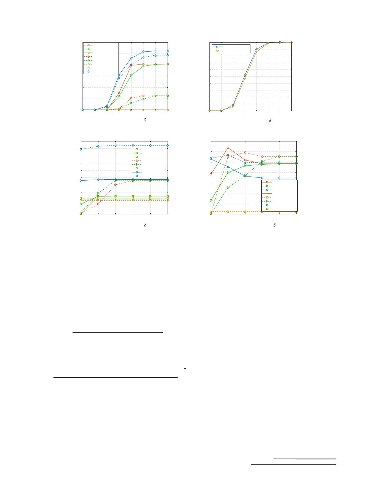
1 Reflection Resource Management for Intell igent Reflecting Surf ace Aided W ireless Netw orks Y ulan Gao, Chao Y ong, Zehui Xiong, Stud ent Memb er , IEEE, J un Zh ao, Membe r , IEEE, Y ue Xiao, Member , IEEE, Dus it Niyato, F ellow , IEEE Abstract —In this paper , the adoption of an intelligent r eflecting surface (IRS) f or multiple user pairs in tw o-hop networks is in- vestigated. Different from the existing studies on IRS that merely fo cused on tun ing the reflection coefficients of all elements, we consider the true reflection reso urce management (RRM ) which builds o n the premise of the introduced modular IRS structure, which is composed of multiple independ en t and controllable modules. In p articu lar , the t rue RRM can be realized via the best triggered module subset identification. T o p ro vide fairness among users, our goal, therefo re, is to maximize the minimum signal- to-interference-plus-noise ratio (SINR) at d esti n ation t ermin als (DTs) via join t triggered module su bset iden tification, transmit power allocation, and the corresponding p assiv e beamforming, subject to p er source terminal (ST) power budgets and modu le size constraint. Whereas this problem is NP-hard due to the module size constraint, to deal w i th it, we transform it int o the group sparse constraint by introducing the mixed ℓ 1 ,F -norm , which yields a suitable semidefinite r elaxation. In order to address this app roxima ted problem, a two-block alter nating direction method of multip liers (AD M M) algorithm is proposed based on its separable structure. Nu merical simulations are used to validate the analysis and assess the p erformance of the proposed algorithm as a fu nction of the system p arameters. In addition, energy efficiency (EE) p erfo rmance comparisons demonstrate the necessity and meanin gfulness of the introduced modular IRS structure. Specifically , f or a given network setting, there is an optimal value of the number of triggered modu les, when the EE is considered. Index T erms —Intelligent reflecting surface (IRS), transmit power allocation, passive beamf orming, reflection resource management, alternating direction and method of multipliers (ADMM), group sp arsity . I . I N T R O D U C T I O N A. Ba ckgr ound and Mo tiva tion I T IS evident that the fast pro lific spre a d of Internet-ena bled mobile devices will brin g to a 1000 -fold in crement of network capacity by 2020 [ 1 ], which c a n no t be supp orted by Y . Gao is with the National K ey Laboratory of Science and T echnology on Communicat ions, Univ ersity of E lectro nic Science and T echnol ogy of China, Chengdu 611731, China, and also with the School of Computer Science and Engineeri ng, Nanyang T echnologica l Univ ersity , Singapo re. C. Y ong i s wit h the Na tional K ey Laborator y of Scie nce and T echnology on Communicat ions, Univ ersity of E lectro nic Science and T echnol ogy of China, Chengdu 611731, China . Z. Xiong, J. Z hao, and D. Niyato are with the School of Computer S cience and Engineering, Nany ang T echnol ogica l Univ ersity , Singapore. Y . Xiao is with the National Ke y Laboratory of Science and T echnol ogy on Communicat ions, Univ ersity of E lectro nic Science and T echnol ogy of China, Chengdu 611731, China, and also with the National Mobile Communicat ions Researc h Laboratory , S outheast Univ ersity , Nanjing 210096, China. the fo r th-gener ation (4G) mobile n etworks, i.e., lon g-term ev o- lution (L TE) an d L TE -advanced (L TE-A) technolog ie s. T here- fore, a lo t of attention from research commu nity was main ly focused on the desig n of fifth generation (5 G) wireless tech - nologies, e.g., heter ogeneou s networks (HetNets), peer-to-peer (P2P) communic a tio ns, massi ve m ultiple-inp u t multiple-outp ut (mMIMO), an d mmW ave comm unication, w h ich shou ld ad- dress hig h q uality of service (QoS), coverage, seamless con- nectivity with a high user speed, an d limited power con- sumption [ 2 ]–[ 4 ]. Howev er , due to th e h ighly d emandin g of forthco ming and fu ture wir e less networks (5G an d beyond), a ser io us issue in the wireless industry today is to meet the soaring demand at the cost of resu lting power consump tion [ 2 ], [ 5 ]. For instan ce, fo r mMIMO, adop ting a higher am ount of b ase station antennas to serve multiple u sers con currently not o nly entails the incr eased rad io frequ ency chains and maintenan c e cost, but also significantly decreases th e overall perfor mance level. T herefor e, addressing th is issue means introdu c ing innovation technolog ies in future /b eyond-5G wire- less networks, wh ich a r e spectral-en e rgy efficient a n d cost- effecti ve [ 6 ], [ 7 ]. As a result, intelligent reflecting surface (IRS) was treated as a pr omising innovation technolo gy f or future/b eyo nd-5G wireless n etworks supp orting reco nfigurab le wireless en vironm e nt via exploiting large software-contro lled reflecting elements [ 8 ]–[ 12 ]. The IRS provides a n ew degree of freedom to fu rther enhan ce the wireless link perform ance v ia proactively steer in g the inciden t radio - frequen cy wa ve towards destination ter minals (DTs) as its impor tant fe a tu re, which is a p romising solution to build a pr ogramm able wireless en vironme nt for 5 G and beyond systems. The IRS-aide d comm u nications refer to the scen ario that a large nu mber of sof tware-c ontrolled reflectin g elements with adjustable p hase shifts for reflecting the incid ent signal. As such, the p hase shifts o f all re flec ting elements ca n be tune d adaptively accor d ing to the state of networks, e . g., the channel condition s and the in cident ang le of the signal b y the sourc e terminal (ST). Notab ly , different from the conventional h alf and f u ll-duplex modes, in IRS-aided commun ications, th e propag ation en vironmen t can be imp roved without incu rring additional noise a t the reflectin g elem ents. Curren tly , co nsid- erable resear ch attention was paid fo r I RS-aid ed com m unica- tions [ 7 ], [ 13 ]–[ 21 ]. Amon g the ear ly contributions in this area, [ 7 ], [ 20 ], [ 21 ] summ arized the main application s an d competi- ti ve advantages in IRS-aided systems. For the IRS-aided point- to-poin t multiple-in p ut-single-o utput (MI SO) wireless system with sing le user , [ 13 ] investigated the total received signal power max imization pro b lem by join tly optimizin g the trans- 2 mit b eamform ing and the passive beamfo rming. In the spir it of these works, a vast corpu s o f literatur e focused on optimizing activ e-passiv e beamf orming f o r unilater al spectr al efficiency (SE) m aximization subject to power constrain t. For instance, [ 14 ] p roposed a fractional progra m ming based altern ating optimization app roach to maximize th e weigh ted SE in IRS- aided MISO downlink commun ication systems. In particular, three assump tions f or the feasible set o f r e flec tion coefficient (RC) were co nsider at IRS, includ ing the ideal RC constrained by pe ak-power , c o ntinuou s p h ase shifter, and discrete ph ase shifter . Meantime, in MISO wir e less systems, th e problem of minim izing the to ta l transmit power at the a c c ess point was co nsidered to energy- efficient acti ve-passi ve b eamform ing [ 15 ], [ 18 ]. [ 15 ] formu late d an d solved the total tran smit power minimization prob lem by active-passi ve beamf o rming d esign, subject to th e signa l-to-interfe rence-plu s-noise ratio (SINR) constraints, whe re each reflectin g element is a co ntinuou s phase shifter . Along this direction , considering the discrete reflect ph ase shifts at th e IRS, th e same optimization problem was studied in [ 18 ]. In add ition, to r educe imp lementation complexity of large dimension s optim ization pro blems, the deep reinf orcemen t learn in g tech nique was incorpo rated into optimal designs fo r IRS-aide d MIMO systems [ 22 ]. Notably , the afo remention ed studies f o r IRS-aided co mmunica tio ns were based on the assump tion that the IRS power consum p tion is ign ored. In contra st, in [ 19 ], an energy efficiency (EE) max- imization problem was inv estigated by developing a realistic IRS power consum ption model, where IRS power consump tion relies on the type an d the r esolution of m eta-element. The com mon assum ption in the existing stu d ies for IRS- aided com m unication s is that all the r eflecting elemen ts reflec t the in c id ent sign al tog ether , i.e., adjusting RC o f each meta- element simultaneou sly . Howe ver , along with the use of a large n umber of high- resolution reflec ting elements, especially with contin u ous pha se shifter s, trigg ering all th e reflecting elements ev ery time m ay result in significan t IRS p ower con- sumption [ 23 ] and high implementation comp lexity . Mo reover , the har d ware suppo rt for th e IRS im plementation is the use of a large numb er of tunable metasurfaces. Specifica lly , the tunability fe a tu re can be realized b y intro ducing mixed-sign al integrated circuits ( I Cs) or d iodes/varactors, which can vary both the resistance an d re actance, offering co mplete lo cal control over the complex surface im pedance [ 8 ]–[ 10 ], [ 2 4 ]. According to the IRS power con sumption mod el p resented in [ 19 ] and the hardware supp ort, trigger in g the entire IRS all the time no t only in curs in creased power consumption , but also en tails the increased latency of adju sting phase-shift and accelerates equipmen t depr e ciation. T o this end , it is ne c e ssary and valuable to achieve the true RRM in IRS-aided systems. B. Novelty and Contribution In this paper, we co nsider the two-hop P2P network in which multiple sing le-antenna STs reach the co r respond ing single-anten na DTs thro u gh an IRS that fo rwards a suitab ly phase-shifted version of the transmitted signal. The goal is to maximize the minimum SINR at DTs via joint de sig n of tr ig- gered module subset identification, transmit power allocatio n, and the cor respond in g passive be a mformer . Spe c ifically , th e novelty an d co ntributions of this pap e r are sum marized in the following a sp ects. 1) Modular IRS Structur e : For the fir st time, we introdu ce a modu lar IRS structu re, which co mposes of multiple indepen d ent an d con trollable modu le s. At the mo dular IRS, each modu le is attach ed with a smart controller, where all the co ntrollers are physically conne c te d v ia dedicated fiber links, thu s, they can exchange in forma- tion with each other in a point- to-point fashion. IRS can be pro grammab le and con trolled by th e con tr oller , and hence, fr om an operation al standp oint, in depend ent module trigg ering can b e impleme n ted easily . 2) T rigger ed Module Subset Iden tification: The true RRM can be realized via the triggered m odule subset iden - tification, which is based on the introd uced modular IRS structure where the reflecting elemen ts are tr iggered indepen d ently b y the c ontroller to which they belong. Specifically , we fo rmulate the prob lem of maximizin g the minimum SINR sub ject to the ma x imum tran sit power at each ST an d the m odule size constrain t. Un- fortun a te ly , due to the module size constraint, obtainin g a g lobally optimal solution r equires a n exha usti ve com- binatorial search over all possible cases, wh ere the NP- hard max-m in SINR p roblem must be solved for each o f these cases. T o this end, we resort to a low-comp lexity and efficient ap proxim ate so lu tion. In pa rticular, a co n- vex relax a tio n to th e hard module size constraint can be derived by replacing the ℓ 0 -norm by the conv ex norm ℓ 1 ,F -norm. Based on this insight, a tr actable c on vex problem c a n b e formu lated from the perspective of group sparse op timization. T o select the best triggered module subset, a two-block alter nating direction method of multiplier s (ADMM) algorith m is pro p osed based on the separa b le stru cture of the dua l of th e appro ximate conv ex p r ogramm ing. Notably , the g lobal co n vergence of th e proposed two-bloc k ADMM algorithm can be established. Subsequen tly , transmit power allocation and the co rrespond ing passi ve beamfo rmer design for the max-min SI NR problem withou t the m odule size co n- straint ar e studied wh ile simultan eously meeting STs’ power budget. In addition, the entire alg orithm (outlined in Alg. 2) exhibits low complexity , since e qs. ( 30 ), ( 32 ), ( 36 ), ( 3 8 ), an d ( 3 9 ) are derived an alytically in clo sed- form and can be com puted directly . 3) P erforman c e Compa rison : Num erical simulatio ns are used to validate the analysis and assess the performa n ce of th e two-block ADMM algorithm as a f unction o f the system pa rameters. Detailed resu lts are provided first when the numb e r o f modules is small, wh ich allows comparin g the ADMM algorithm with the metho d o f exhaustiv e search ( MES) solu tion. T he resu lts show that the two-blo ck ADMM alg o rithm fo r the approxim a te conv ex p roblem con verges to a nea r op timal so lution. T o gain insigh t into the introdu ced mod ular IRS structure, energy efficiency (EE) perform ance co m parison is gi ven subsequen tly , where th e EE is defin ed a s th e ratio of achiev able sum rate and the overall power co nsumption . The further simulation results show that there exists 3 ĂĂ ĂĂ 67 67 K '7 K '7 h M h M g g K g M K g K h K M h &RQWUROOHU P R G X O H PRGXOH m PRGXOH M Ă Ă Ă Ă Ă Ă Ă Ă 7ULJJHUHG PRGXOH 8QWULJJHUHG PRGXOH &RQWUROOHU m Ă ,QWHUIHUHQFHFKDQQHO )LEHUOLQN Fig. 1. An IRS-aid ed P2P network with K ST -DT pairs and an IRS, which has M m odules. an o p timal value o f trigg ered modules for a g i ven network setting, which implies that the in troductio n o f the m odular IRS structure is meanin gful. C. P aper Ou tlin e and Notation The reminder of this paper is organ ized as follows. Th e system model, trigge red mod ule subset identification, the con - vex relax ation fo r the o riginal pr oblem, and th e app roximate optimization prob lem formu lation are presen ted in Section II . Section III presents the pro posed two-block ADMM a lgo- rithm. Section IV repo rts nu merical re su lts th at ar e used to assess the per forman ce of th e prop osed algorith m and fu rther demonstra te the meaning fulness of the mod ular I RS structure. Conclusions ar e presented in Section V . Matrices and vector s are denoted by b old letters. I N , 0 N , and e n are the N × N identity matrix, the N × 1 all-z ero column vector, and th e N × 1 elementary vector with a one at the n th position, respectively . A T , A † , A − 1 , an d || A || F denote transpose, Hermitian, in verse, and Frob enius nor m of matrix A , respe cti vely . Notation bld g { A 1 , . . . , A M } deno tes a block diag onal matrix with A m being th e m -th diagon al block, and [ A ] i,j denotes the ( i, j ) th entry of A . [ A , a ] and [ a , a ] den o te the splicing of ma tr ix and vector as well a s vector and scalar, r espectiv ely . Re ( · ) , Im ( · ) , and | · | d enote the real par t, imag in ary part, a n d modu lus of th e enclosed vector, respectively . I I . S Y S T E M M O D E L A N D P RO B L E M F O R M U L A T I O N A. S ystem Mode l As shown in Fig. 1 , we consider a two-ho p link of slowly- varying P2P n etwork where an IRS is adjoined to K user pairs, where a user p air includ es one ST and one DT , and each user terminal is equ ipped with a sin gle antenn a. Let S := { s 1 , s 2 , . . . , s K } an d D := { d 1 , d 2 , . . . , d K } b e the sets of STs and DT s, respectively . The ind ex set of u ser pairs is denoted by K := { 1 , 2 , . . . , K } . The mod ular I RS structur e as shown in Fig. 1 is composed of mu ltiple mod u les, eac h of which is attache d with a smart controller, wher e all the controller s can c o mmunica te with e a c h o ther in a poin t-to- point fashion v ia fiber lin k s. This setting can be regarded as a g eneralization of the IRS architecture introduced in [ 7 ]. W e suppose that the en tire I RS co nsists of M indepe ndent and controllab le modules, where e a ch mod u le has L r eflecting elements, and thus, the num ber of the to tal reflecting ele- ments a t IRS is N = M L. Let L := { 1 , 2 , . . . , L } be the index set of reflecting elements o f ea c h mod ule. Define M := { 1 , 2 , . . . , M } as th e set of modu les at IRS. In the following, we u se m to denote the index o f a mod ule or controller within M ( i.e., m ∈ M ). The ch annels o f two-hop commun ications are assum e d to experience quasi-static block fading, i.e., the chann el coe fficients from the STs to the IRS and th e IRS to the DTs remain c o nstant d uring each time slot, but may vary from one to an other [ 25 ]. Let h k,m ∈ C L × 1 and g m,k ∈ C L × 1 denote the uplink channel vector fr om ST k to the m th mod ule of IRS an d th e d ownlink channe l vector f rom modu le m to DT k , respectively . The associated passiv e beamfromer at the m th mo d ule a t IRS deno ted by Φ Φ Φ m = diag [ φ ( m − 1) L +1 , . . . , φ ( m − 1) L + l , . . . , φ mL ] ∈ C L × L , where φ ( m − 1) L + l is the l -th entry of reflec tin g coefficient matrix at mo d ule m , ∀ m ∈ M , l ∈ L . W e assume that all the m odules can po tentially serve the user pairs tran smitting. Note th at if all mod ules are trigg ered to serve the ST -DT commun ications, th e problem beco mes a special case which is simpler to solve. T he passive beamform er at IRS den oted by Φ Φ Φ ∈ C N × N , and the associated chan nel from ST k to the IRS and th e chann el from the IRS to DT k , de n oted by h k ∈ C N × 1 and g k ∈ C N × 1 , respe cti vely , are expressed as follows: Φ Φ Φ := bldg { Φ Φ Φ 1 , Φ Φ Φ 2 , . . . , Φ Φ Φ M } , (1a) h k := [( h k, 1 ) T , ( h k, 2 ) T , . . . , ( h k,M ) T ] T , ∀ k ∈ K , (1b) g k := [( g 1 ,k ) T , ( g 2 ,k ) T , . . . , ( g M ,k ) T ] T , ∀ k ∈ K . (1c) In additio n, in the fo llowing analy sis–f or the sake of simplicity–we co nsider that th e reflectin g coefficient φ n = β n e j θ n with continuo us p hase shift and continuo u s amplitude attenuation as X , { φ ( m − 1) L + l : | φ ( m − 1) L + l | ≤ 1 , ∀ m ∈ M , l ∈ L} . I n pr actice, the feasible set of reflecting coefficient X migh t be more comp licated, such as in [ 11 ], [ 14 ], [ 1 9 ], but this feature is beyond the focus of this paper . The ma in pu r pose of this p aper is to realize the true RRM by intro ducing the modular IRS structure. Specifically , f or the form ulated max - min SINR pr o blem under module size con straint, th e true RRM can be implemen ted v ia the triggered modu le subset identification. Let z k denote the da ta symb ol of ST k and write p k for its correspo n ding power . The signal received at DT k via I RS- aided link is expre ssed by y k = g † k Φ Φ Φ K X k =1 √ p k h k z k + u k = g † k Φ Φ Φ √ p k h k z k + g † k Φ Φ Φ K X j =1 ,j 6 = k √ p j h j z j + u k , ∀ k ∈ K , (2) where u k ∼ C N (0 , σ 2 ) is the therma l noise experienc ed b y DT k and the second term accounts for the interf erence expe- rienced b y ST -DT p air k fr om oth e r user pairs j ∈ K , j 6 = k . Then, based on ( 2 ) the received SINR at d k is given by SINR k = p k | g † k Φ Φ Φ h k | 2 P K j =1 ,j 6 = k p j | g † k Φ Φ Φ h j | 2 + σ 2 , ∀ k ∈ K . (3) 4 The design prob lem is to max imize the minimu m SI NR at all DT s, wh ile satisfyin g the STs’ tr ansmit power co nstraint p max k , ∀ k ∈ K , and the reflecting coefficient co n straint X ; that is max { Φ Φ Φ , { p k } K k =1 } min k SINR k (4) s.t. p k ≤ p max k , and X , ∀ k ∈ K . (5) The optimization pro blem ( 4 )-( 5 ) is non-co n vex, du e to the non-co n vex ob jectiv e fu nction w .r .t. { p k } K k =1 and Φ Φ Φ , and there is no known efficient and standard metho d to obtain an optimal solution for it. Th is motiv ates the pursu it o f effecti ve meth od for a su boptimal solutio n via exploiting th e special structure of problem itself. The most suitable tool for this similar pro blems is th e genera lize d fractional p rogram s [ 26 ]–[ 28 ], since the numerato r and den ominator of SINR are continu ous fu nctions on variables. For this IRS-aid ed two-hop co mmunicatio n , the suboptimal solution o f ( 4 )-( 5 ) can be obtained effecti vely by u sing gen eralized fractio nal prog r ams and th e alternatin g optimization techn ique [ 29 ] to separ ately and iteratively solve for { p k } K k =1 and Φ Φ Φ [ 7 ], [ 1 1 ], [ 15 ], [ 1 9 ]. B. T rigger e d Mod ule Sub set I dentificatio n In this section, suppo se now that only Q ≤ M m odules are available, and thu s only QL reflecting elem ents can be serving the user pairs simultaneously . From [ 23 ], the design problem is to jointly select th e best Q ou t of M m odules, and d esign the transmit power { p k } K k =1 and th e cor respondin g passiv e b eamform er so th a t th e minimu m SINR among DTs is m aximized, subject to the p ower budget at each ST an d reflecting co efficient constra in t. Define the N × 1 vector φ φ φ := [( φ φ φ 1 ) T , ( φ φ φ 2 ) T , . . . , ( φ φ φ M ) T ] T , where φ φ φ m := [ φ ( m − 1) L +1 , . . . , φ mL ] T ∈ C L × 1 is the m th block of vector φ φ φ , ∀ m ∈ M . If module m ∈ M is no t triggered , vector φ φ φ m must be set to zero, i.e., φ φ φ m = 0 . Hence, the max-min SINR pr o blem v ia jo int tr iggered mo dules ide n ti- fication, power allocation, and passiv e beamformer design can be expressed b y (P0) max { Φ Φ Φ , { p k } K k =1 } min k SINR k (6) s.t. S ( mod ule ) ≤ Q , and ( 5 ) , (7) where S ( mo dule ) d enotes the n u mber of trigger ed modu les, and Q ≤ M is the upper bo und o f this num ber . Note tha t (P0) is an NP-har d problem due to the no n-conve x constraint S ( module ) ≤ Q , and solv ing (P0) req uires an exhaustive combinato rial search over all Q M possible patter n s. Thu s, in the fo llowing, we aim to develop compu tationally efficient method to o btain a sub-o p timal solution. Sp ecifically , instead of the hard mod u le size co nstraint S ( module ) ≤ Q , a sparsity- inducing appr oximation [ 23 ], [ 30 ] can be employed to o b tain a co nvex relaxation of (P0). C. Co n ve x Relaxa tio n and Pr o blem F ormulation Define A k = diag [ g † k ] ∈ C N × N , th e N × 1 vec- tor ¯ h j,k = A k h j , and the ( K N ) × 1 vector ¯ h k = [( ¯ h 1 ,k ) T , ( ¯ h 2 ,k ) T , . . . , ( ¯ h k,k ) T , . . . , ( ¯ h K,k ) T ] T . Thus, the ex- pression o f SINR k in ( 3 ) can be rewritten as SINR k = p k φ φ φ † ¯ h k,k ¯ h † k,k φ φ φ σ 2 + P K j =1 ,j 6 = k p j φ φ φ † ¯ h j,k ¯ h † j,k φ φ φ = ¯ φ φ φ † k ¯ h k,k ¯ h † k,k ¯ φ φ φ k σ 2 + P K j =1 ,j 6 = k ¯ φ φ φ † j ¯ h j,k ¯ h † j,k ¯ φ φ φ j , (8) where ¯ φ φ φ k = √ p k φ φ φ, ∀ k ∈ K . Define the N × K ma trix ¯ Φ Φ Φ = [ ¯ φ φ φ 1 , ¯ φ φ φ 2 , . . . , ¯ φ φ φ K ] . Moreover, define th e L × K ma- trix ¯ Φ Φ Φ m := [ √ p 1 φ φ φ m , √ p 2 φ φ φ m , . . . , √ p K φ φ φ m ] , where √ p k φ φ φ m is the m -th block of ¯ φ φ φ k . Thus, ¯ Φ Φ Φ ca n be rewritten as ¯ Φ Φ Φ = [( ¯ Φ Φ Φ 1 ) T , ( ¯ Φ Φ Φ 2 ) T , . . . , ( ¯ Φ Φ Φ M ) T ] T . Define the M × 1 vector ˜ φ φ φ := [ || ¯ Φ Φ Φ 1 || F , || ¯ Φ Φ Φ 2 || F , . . . , || ¯ Φ Φ Φ M || F ] T . If mo d ule m is not be triggered , all the entries of ma tr ix ¯ Φ Φ Φ m must be set to zero. This means that ¯ Φ Φ Φ m = 0 , i.e., the m -th block of each ¯ φ φ φ k , for all K ST -DT pairs, must b e set to zero simultaneou sly . Hence, the hard modu le size con straint in ( 7 ) is equ ivalent to || ˜ φ φ φ || 0 ≤ Q, (9) where the ℓ 0 -norm is the num ber o f nonzer o en tr ies of ˜ φ φ φ, i.e., || ˜ φ φ φ || 0 := m : || ¯ Φ Φ Φ m || F 6 = 0 . By in troducin g an aux iliary variable γ and replacing the har d mo dule size constrain t, a n ℓ 0 -norm pen a lty can be employed to p romote sparsity leading to max φ φ φ, { p k } K k =1 ,γ γ − α || ˜ φ φ φ || 0 s.t. SINR k ≥ γ , and ( 5 ) , k ∈ K , (10) where α > 0 is a po siti ve real tu ning p a r ameter tha t con trols the sparsity of the solution, i.e., the nu mber of trigg ered modules. Pro blem ( 10 ) strikes a balance b etween ma x imizing the minimum SINR amon g ST -DT pair s an d min imizing the number o f trig g ered modu les, where a larger α imp lies a sparser solution . N o te that for any α, ther e is a co rrespond ing Q for which prob lems ( 10 ) an d (P0) yield the same sparse solution, an d th us the focu s is placed on ( 10 ) on ly . How- ev er , since the optimization prob lem ( 10 ) is non c on vex and generally impo ssible to so lve as its solution usually req uires an intractab le combinatoria l search. The mixed ℓ 1 , 2 -norm, which was first presented in the co ntext of the gro up lea st- absolute selection and shrink age operator (group La sso ) [ 31 ], the tr ig gered mod ule size can be effecti vely ap proxima te d by replacing th e ℓ 0 -norm with ℓ 1 , 2 -norm, i. e., || φ φ φ || 1 , 2 , P M m =1 || φ φ φ m || 2 . In ou r scena r io, the m ixed convex norm ℓ 1 ,F of matrix [ 32 ] can be d e fined as || ¯ Φ Φ Φ || 1 ,F = M X m =1 || ¯ Φ Φ Φ m || F . (11) Note that || ¯ Φ Φ Φ || 1 ,F = || ˜ φ φ φ || 1 . The mixed ℓ 1 ,F -norm behaves as the ℓ 1 -norm on ˜ φ φ φ, which implies that each || ¯ Φ Φ Φ m || F (or equiv alently ¯ Φ Φ Φ m ) is en courage d to b e set to zero , theref ore inducing grou p-sparsity . From [ 30 ], the ℓ 1 -norm is known to offer the closest conve x appro ximation to the ℓ 0 -norm , and the sparsity-pro m oting n ature of ℓ 1 -norm minimization was empirically confirmed [ 33 ], [ 34 ], where the objective functio n 5 of ( 10 ) can be replaced by γ − α || ¯ Φ Φ Φ || 1 ,F . Natur ally , the h ard module size constraint in pro gram (P0) c a n be relaxed as α M X m =1 || ¯ Φ Φ Φ m || F ≤ δ, (12) where δ > 0 con trols th e row block spar sity of ¯ Φ Φ Φ . Applying the conv ex relax ation of module size constraint, (P0) is eq uiv alen t to (P1) max ¯ φ φ φ k min k SINR k (13) s.t. ( 5 ) an d ( 12 ) . (14) Remark 1: Similar to the weighted ℓ 1 minimization p roblem [ 30 ], the weigh t α can be regarde d as a free para m eter in the conv ex relaxation, wh o se value c a n b e chosen to av o id trivial solutions (i.e, ¯ Φ Φ Φ m = 0 or ¯ Φ Φ Φ m 6 = 0 , ∀ m ∈ M ). Notably , in ( 12 ), b oth α and δ affect the car dinal num ber of the trigger e d module subsets together . As men tioned before, the sparsity is negatively co rrelated with α , while is p o siti vely cor related with δ. In spired by the iterative algorithm o f redefining the weights [ 30 ], intuitively , para m eter α should relate inversely to δ, con seq uently , α can be set to 1 / ( δ + 0 . 01 ) . Our motiv ation for introducing 0 . 0 1 in the α setting is to provide stability and ensure feasibility . In th is setting, the number o f triggered mod- ules increases as the param e ter δ increases un til a p proach ing the u pper bou nd o f the modu le q uantity . Lemma 1: If δ ≥ − 0 . 01+ q (0 . 01) 2 + √ 16 M K N max k { p max k } 2 , the triggered modu le size is M , since the mod ule size co nstraint in ( 12 ) is in a cti ve. Pr oof 1: Please to refer to App endix A. As Lemma 1 states, th ere is a rang of favorable pa- rameter δ for a g iv en system setting (i.e., M , K , N , and { p max k } K k =1 ), wh ich suggests that the po ssibility of co n- structing a fav orable set of δ based so lely on the infor- mation ab out the system magnitudes. T o efficiently co ntrol the tr iggered mod ule size, δ sho uld be within the range o f 0 , − 0 . 01+ q (0 . 01) 2 + √ 16 M K N max k { p max k } 2 ! . By introd ucing an aux iliary variable γ , the joint trigger ed module subset identificatio n, transmit power allocatio n, and the co rrespon ding p assi ve beamf ormer design problem (P1) can thus be eq uiv alent to (P1–1) max φ φ φ,γ , { p k } K k =1 γ (15) s.t. SINR k ≥ γ , ∀ k ∈ K (16) ( 5 ) an d ( 12 ) . (17) It is clear f rom prob lem (P1–1 ) that fo r large γ , (P1– 1) may be in feasible d ue to the resulting strin gent SI NR co nstraints, strong interfere n ce, an d insufficient numb er o f triggered mod- ules. T o th is end, in the following, prob lem ( 15 )–( 17 ) ca n b e solved efficiently v ia bisection me th od for feasibility checking. Although the feasibility chec k ing of (P1 - 1) can be solved by CVX [ 35 ], th e pr oblem d imension m ay be transfo rmed to an additional challengin g issue, due to th e inc reasing co llected informa tio n o f all the ST -DT pairs and the IRS, wh en the number o f them is larger . I n th e next section , to develop a par tially distributed algorithm , we fit ( 15 )–( 17 ) into the ADMM fr a mew ork [ 29 ] and then reform ulate it as a separable group La sso problem [ 31 ]. Finally , a c u stom-made p artially distributed algorithm is d ev eloped. The propo sed algorithm is computatio nally efficient since each step o f ADMM can be computed in closed-f o rm. I I I . T W O - B L O C K A D M M - B A S E D O P T I M A L S O L U T I O N Our proposed A D M M-based solution framew ork is com- posed o f two phases. The first p hase is to identify the triggered module sub set an d the second phase is to solve th e o riginal max-min SINR p roblem free fr om the mod ule size con straint ( 12 ). A. T rigger e d Mod ule Subset Id entification As demonstra ted in Section II, for a given γ > 0 , the design p r oblem ( 15 )–( 17 ) beco m es the feasibility test on e. In this context, the challeng e in solving prob lem ( P1 –1) lies in the fact that its o bjective is non-differentiab le an d th a t the feasible set is nonco n vex. T o proceed fu rther, fo r the fixed γ , we observe that (P1– 1 ) is fe a sible if and o nly if the solution of the following optimiza tion problem (P1–2 ) is lower th a n δ, where (P1 –2) is given b y (P1–2) min ¯ Φ Φ Φ M X m =1 α || ¯ Φ Φ Φ m || F (18) s.t. p (1 + γ − 1 ) ¯ h † k,k ¯ φ φ φ k ≥ || [ ¯ h k † e Φ Φ Φ , σ ] || 2 , ∀ k ∈ K (19) ¯ φ φ φ † k e n e † n ¯ φ φ φ k ≤ p max k , n ∈ N ; k ∈ K , (20) Im ( ¯ h † k,k ¯ φ φ φ k ) = 0 , ∀ k ∈ K . (21) The constraint ( 19 ) o f ( P1–2) is the refo rmulation of SINR constraint ( 16 ) relies o n the seco nd-or der cone p rogram [ 36 ], where the ( N K ) × K matrix ˜ Φ Φ Φ is defined as ˜ Φ Φ Φ = bldg { ¯ φ φ φ 1 , ¯ φ φ φ 2 , . . . , ¯ φ φ φ K } . Define e H = [ ¯ h 1 , ¯ h 2 , . . . , ¯ h K ] ∈ C ( N K ) × K . T o dev elop the perf ormance gains brou ght by the pa ssive be amformin g of IRS, in the r est of th is pap er , it is assumed th at th e channels h k and g k are perfectly known at s k , ∀ k ∈ K [ 19 ]. All in volved chann els can be estimated at IRS via their train ing signals, who se implemen tation is based o n the assumption that each r eflecting element is equipped with a low-po wer receive RF chain [ 7 ]. Mo reover , let us intro duce a K × ( K + 1) auxiliary matrix F = [ e H † e Φ Φ Φ , σ 1 K ] . Furthermo re, define f k,k = ¯ h † k,k ¯ φ φ φ k and f k = [ ¯ h k † e Φ Φ Φ , σ ] ∈ C 1 × ( K + 1) as th e k -th diago n al elemen t and the k -th row vector of F , respectively . U sin g these d e finitions an d introdu c ing a matrix v ariable W = ¯ Φ Φ Φ ∈ C N × K , problem ( 18 )–( 21 ) can be refo rmulated as the following prob lem: ( P1–3 ) min { { ¯ φ φ φ k } k ∈K , W , { F } } M X m =1 α || W m || F (22) s. t. p (1 + γ − 1 ) f k,k ≥ || f k || 2 , ∀ k ∈ K (23) ¯ φ φ φ † k e n e † n ¯ φ φ φ k ≤ p max k , ∀ n ∈ N ; k ∈ K , (24) W = ¯ Φ Φ Φ , F = [ e H † e Φ Φ Φ , σ 1 K ] . (25) 6 (P1–3) is a conv ex minim ization pro blem, and ther e fore, the duality gap between (P1–3) and its augmented duality prob lem is zero. This means that the optimal solution of (P1– 3 ) can be obtained b y app lying the aug mented Lag rangian duality th e ory [ 37 ]. The p artial augmen ted L agrangian function of (P1–3) can be written as L c ( { ¯ φ φ φ k } k ∈K , W , F , Λ Λ Λ , Ψ Ψ Ψ) , M X m =1 α || W m || F + Re { Tr [ Λ Λ Λ † ( W − ¯ Φ Φ Φ)] } + c 2 || W − ¯ Φ Φ Φ || 2 F + Re { Tr [ Ψ Ψ Ψ † ( F − [ e H † e Φ Φ Φ , σ 1 K ])] } + c 2 || F − [ e H † e Φ Φ Φ , σ 1 K ] || 2 F , (26) where c > 0 is th e penalty factor; Λ Λ Λ ∈ C N × K and Ψ Ψ Ψ ∈ C K × ( K +1) are the Lagrang ian matrix multip lier s fo r W = ¯ Φ Φ Φ and F = [ e H † e Φ Φ Φ , σ 1 K ] , respec tively . Note that th e reform ulated SINR co nstraints ( 23 ) as well as the bo undar y constraint ( 24 ) are not taken into the augmented L agrangia n function an d they will be integrated into the optima l solu tion in the fo llowing. Particularly , we focu s on solvin g: ( P1–4 ) max { Λ Λ Λ , Ψ Ψ Ψ } min { { ¯ φ φ φ k } k ∈K , W , F } L c { ¯ φ φ φ k } k ∈K , W , F , Λ Λ Λ , Ψ Ψ Ψ s. t. p (1 + γ − 1 ) f k,k ≥ || f k || 2 , ∀ k ∈ K ¯ φ φ φ † k e n e † n ¯ φ φ φ k ≤ p max k , ∀ n ∈ N ; k ∈ K . (27) W e need to deco uple the optimization variables in L c to make (P1 –4) intractable. T o be spe c ific, dividing { ¯ φ φ φ k } k ∈K , W , and F into two blocks of { ¯ φ φ φ k } k ∈K and { W , F } , we can apply the two-blo ck ADMM framework [ 29 ] to solve (P1–4). I n each iteration t , we first update { ¯ φ φ φ k } k ∈K by solving P ¯ φ φ φ k P ¯ φ φ φ k : min ¯ φ φ φ k Re { Tr [ λ λ λ k † ( w k ( t ) − ¯ φ φ φ k )] } + c 2 || w k ( t ) − ¯ φ φ φ k || 2 2 + Re { Tr [ ψ ψ ψ k † ( f k ( t ) − ¯ H k † ¯ φ φ φ k )] } + c 2 k f k ( t ) − ¯ H k † ¯ φ φ φ k k 2 2 s.t. ¯ φ φ φ † k e n e † n ¯ φ φ φ k ≤ p max k , ∀ k ∈ K ; n ∈ N , (28) where w k ∈ C N × 1 and λ λ λ k ∈ C N × 1 represent the k -th colu mn of m atrices W and Λ Λ Λ , resp ectiv ely; and ψ ψ ψ k ∈ C K × 1 and f k ∈ C K × 1 are the k -th column of matrices Ψ Ψ Ψ and F , resp ectiv ely; ¯ H k = [ ¯ h k, 1 , ¯ h k, 2 , . . . , ¯ h k,K ] ∈ C N × K . With the o btained ¯ Φ Φ Φ (or { ¯ φ φ φ k } k ∈K ), and then better so lutions for W and F can be updated by solving the following prob lem: P W , F : min W , F L c ( ¯ Φ Φ Φ( t + 1) , W , F , Λ Λ Λ , Ψ Ψ Ψ) s.t. p (1 + γ − 1 ) f k,k ≥ || f k || 2 , ∀ k ∈ K . (29) Then, as sh own in App e n dix B, the o ptimal ¯ φ φ φ k and W ca n be obtain ed as in Theo rem 1. Theor em 1 : For g iv en Λ Λ Λ and Ψ Ψ Ψ , th e o ptimal { ¯ φ φ φ k } K k =1 of minimizing P ¯ φ φ φ k is given by ¯ φ φ φ k ( t + 1) =( c I N × N + c ˜ h k ¯ H k † + 2 N X n =1 µ k n e n e † n ) − 1 × ( λ λ λ k ( t ) + c w k ( t ) + ˜ h k ψ ψ ψ k ( t ) + c ¯ H k f k ( t )) , (30) where µ k n ≥ 0 is the L a g rangian mu ltip lier of bou ndary constraint in ( 24 ). Mo reover , the optimal W is g i ven by solving the following uncon strained p roblem min W M X m =1 α || W m || F + Re { Tr [ Λ Λ Λ † ( W − ¯ Φ Φ Φ( t + 1))] } + c 2 || W − ¯ Φ Φ Φ( t + 1) || 2 F . (31) Using the first-or der op timality condition for the optima l solution W m ( t + 1) , we h av e W m ( t + 1) = ( 0 , if || Ξ Ξ Ξ( t ) || F ≤ α ( || Ξ Ξ Ξ m ( t ) || F − α ) Ξ Ξ Ξ m ( t ) c || Ξ Ξ Ξ m ( t ) || F , otherwise , (32) where Ξ Ξ Ξ m ( t ) = c ¯ Φ Φ Φ m ( t + 1) − Λ Λ Λ m ( t ) , and Λ Λ Λ m ∈ C L × K , W m ∈ C L × K , and ¯ Φ Φ Φ m ∈ C L × K are th e m -th row block s of matrices Λ Λ Λ , W , and ¯ Φ Φ Φ , re spectiv ely , ∀ m ∈ M . Pr oof 2: See Appen dix B. W ith the ob tained optim a l { ¯ φ φ φ k } k ∈K , the o ptimal m ultiplier µ k n of the boun d ary constraint ( 24 ) can be optimally obtained by µ k n = p max k − ¯ φ φ φ † k ( t + 1) e n e † n ¯ φ φ φ k ( t + 1) + , ∀ k ∈ K ; n ∈ N , (33) where ( x ) + = max { x, 0 } . Finally , we op timize F in ( 29 ) giv en fixed ¯ Φ Φ Φ . The problem of F of ( 29 ) is expressed as P F : min F Re { T r [ Ψ Ψ Ψ † ( t )( F − [ e H † ˜ Φ Φ Φ( t + 1) , σ 1 K ])] } + c 2 || F − [ e H † e Φ Φ Φ( t + 1) , σ 1 K ] || 2 F s.t. p γ − 1 f k,k ≥ || f − k,k || 2 , ∀ k ∈ K , (34) where f − k,k ∈ C 1 × K denotes the remaining subvector of f k ∈ C 1 × ( K + 1) after removing the elemen t f k,k , i.e ., f − k,k = [ f 1 ,k , . . . , f k − 1 ,k , f k +1 ,k , . . . , f K +1 , k ] ∈ C 1 × K . Similar to [ 32 ], in order to find the optim al F f or P F with low c o m- putational com plexity , we d ivide th e optimizatio n problem of F into K ind ependen t subpr oblems of f k , ∀ k ∈ K , wh ich are solved in par allel, where the subp r oblem is g i ven by min f k Re T r ψ ψ ψ k ( t ) † ( f k − b k ( t + 1)) + c 2 || f k − b k ( t + 1) || 2 2 s.t. p γ − 1 f k,k ≥ || f − k,k || 2 , (35) where ψ ψ ψ k ∈ C 1 × ( K + 1) and b k ∈ C 1 × ( K + 1) denote the k -th row vectors of Ψ Ψ Ψ and [ e H † e Φ Φ Φ , σ 1 K ] , respectively . Define ψ k,k as the k - th elemen t of ψ ψ ψ k and ψ ψ ψ − k,k as th e remainin g subvector after rem oving ψ k,k . Similarly , we d efine b k,k and b − k,k . Problem ( 35 ) is a co n vex minimization problem . Moreover , it can be verified that the Slater’ s constra in t qualification is satisfied [ 36 ]. The refore, the duality gap betwee n pro blem ( 35 ) and its du ality pr oblem is zero. This m eans that the optima l solution of problem ( 35 ) can be obtained by applyin g the Lagrang e duality theory [ 36 ]. In the f o llowing Theorem 2, the optimal f k can be obtain ed via exploiting the Karush- Kuh n - T ucker (KKT) cond itio ns o f p roblem ( 35 ). 7 Theor em 2: Given Ψ Ψ Ψ , fix ing ¯ Φ Φ Φ( t + 1) , the o ptimal f k is ( f k,k ( t + 1) = cb k,k ( t +1) − ψ k,k ( t )+ √ γ − 1 ε k c f − k,k ( t + 1) = c b − k,k ( t +1) − ψ ψ ψ − k,k ( t ) c + ε k ρ k , (36) where ρ k = ( || f − k,k ( t + 1) || F ) − 1 , ε k ≥ 0 is the d ual variable intro d uced f or the SINR constraint, which is op timally determined b y ε k = 1 1 + γ [ γ || c b − k,k ( t + 1) − ψ ψ ψ − k,k ( t ) || 2 − √ γ ( cb k,k ( t + 1) − ψ k,k ( t ))] . (37) Pr oof 3: See Ap p endix C. After o b taining the o p timal ¯ Φ Φ Φ , W , an d F , we u pdate the Lagrang ian matrix multipliers in prob lem ( P1 –4), i.e., Λ Λ Λ an d Ψ Ψ Ψ . It has be e n shown in [ 38 ] that the well known subgradien t based method can be em ployed iteratively to find the optim al solutions of Λ Λ Λ an d Ψ Ψ Ψ . Similar to the updating of variables { W m } M m =1 and { f k } K k =1 , upd ating Λ Λ Λ and Ψ Ψ Ψ are also separable . Specifically , for Λ Λ Λ m and ψ ψ ψ k , the pointwise upd ate eq u ations are given by Λ Λ Λ m ( t + 1) = Λ Λ Λ m ( t ) + c W m ( t + 1) − ¯ Φ Φ Φ m ( t + 1) (38) ψ ψ ψ k ( t + 1) = ψ ψ ψ k ( t ) + c ( f k ( t + 1) − [ ¯ H k † e Φ Φ Φ( t + 1) , σ ]) . (39) B. Max -Min SINR Op timization In this section , we solve the joint transmit power allocation and p assi ve b eamform er design problem when the trig g ered module subset is identified. More precisely , for the orig in al max-min SINR pr oblem (P1) , the mod ule size constraint ( 12 ) is dr opped a n d the diagon al blocks of Φ Φ Φ c o rrespon d ing to th e non-tr ig gered modules are forced to be zero. For conv enience to illustrate, the phase-shif t matrix with iden tified trigger ed modules den o ted by F Φ Φ Φ . Particularly , we focus on solving : max { p k } k ∈K , F Φ Φ Φ min k ∈K p k | g † k F Φ Φ Φ h k | 2 P K j =1 ,j 6 = k p j | g † k F Φ Φ Φ h j | 2 + σ 2 , s.t. ( 5 ) (40) Note th at ( 40 ) can be efficiently and optima lly solved by employing the alter n ating an d optimizatio n tech nique [ 39 ] to separately and iteratively solve f or { p k } k ∈K and F Φ Φ Φ . I n the rest of this section , the op tim ization with re spect to F Φ Φ Φ for fixed { p k } k ∈K , and with respect to { p k } k ∈K for fixed F Φ Φ Φ will be treated separately . 1) O p timizing Phase-Sh ift Matrix F Φ Φ Φ : Let F φ φ φ ∈ C N × N denote the vectorization of diago nal ma tr ix F Φ Φ Φ . Substituting ¯ h j,k into the ob je c ti ve functio n of ( 40 ), then, p k | g † k F Φ Φ Φ h k | 2 = p k F φ φ φ † ¯ h k,k ¯ h † k,k F φ φ φ , P K j =1 ,j 6 = k p j | g † k F Φ Φ Φ h j | 2 + σ 2 = P K j =1 ,j 6 = k p j F † φ φ φ ¯ h j,k ¯ h † j,k F φ φ φ + σ 2 for all k and j. Ther efore, for a fixed transmit power a llo cation { p k } K k =1 , problem ( 40 ) can be transfo rmed into the following problem : max F φ φ φ min k p k F φ φ φ † ¯ h k,k ¯ h † k,k F φ φ φ P K j =1 ,j 6 = k p j F † φ φ φ ¯ h j,k ¯ h † j,k F φ φ φ + σ 2 , s.t. X . (41) By intro ducing parameter γ out , pro blem ( 41 ) is eq uiv ale n t to Algorithm 1 Max-min SINR Optim ization When the T rig- gered Mod u le Subset is Id entified 1: In itialize F (0) φ φ φ and p (0) to feasible values; initialize the upper bou nd ¯ γ in = ¯ γ out and th e lower bound γ in = γ out of SINR in bisection, an d set the itera tio n num ber τ = 0 . repeat 2: For giv en p ( τ ) , u pdate γ out = ¯ γ out + γ out 2 , so lve ( 42 )-( 44 ) by CVX, if CVX Status is Solved , update γ out = γ out ; else , CVX Statu s is NAN , upd ate ¯ γ out = γ out ; 3: if γ out conv erges, i.e., | ¯ γ out − γ out | ≤ ǫ, denote γ ( τ +1) out , F ( τ +1) φ φ φ be th e optimal solution; 4: For given F φ φ φ ( τ ) , upd ate γ in = ¯ γ in + γ in 2 , solve ( 45 ) b y CVX, if CVX Status is Solved , update γ in = γ in ; else , CVX Statu s is NAN , upd ate ¯ γ in = γ in ; 5: if γ in conv erges, i.e., | ¯ γ in − γ in | ≤ ǫ, denote γ ( τ +1) in , p ( τ +1) be the optimal solution; 6: until | γ out − γ in | ≤ ǫ . solving problem ( 42 )-( 44 ), which can be solved v ia a b isection proced u re of feasibility ch ecking max F φ φ φ ,γ out γ out (42) s.t. q p k (1 + γ − 1 out ) ¯ h † k,k F φ φ φ ≥ k [ F T φ φ φ ¯ h † k diag { √ p 1 1 N , . . . , √ p K 1 N } , σ ] k 2 , ∀ k ∈ K (43) Im ( ¯ h † k,k F φ φ φ ) = 0 , ∀ k ∈ K ; and X , (44) where h F T φ φ φ ¯ h † k diag { √ p 1 1 N , . . . , √ p K 1 N } , σ i is the 1 × ( K + 1) row vector . The feasibility checkin g of ( 42 )-( 44 ) can be solved directly , e.g., by CVX, sinc e it is a second- order co ne progr am. 2) O p timization with Respect to the P ower Alloca tion { p k } k ∈K : For the case wh e re F φ φ φ is fixed and the objective is the op timization over p = [ p 1 , p 2 , . . . , p K ] T , co nsequently , we focus on our attention in the fo llowing op tim ization prob le m max { p k } K k =1 min k p k | ¯ h † k,k F φ φ φ | 2 P K j =1 ,j 6 = k p j | ¯ h † j,k F φ φ φ | 2 + σ 2 , s.t. p k ≤ p max k . (45) Like wise, the above m ax-min SINR pro blem is equ i valent to the following problem , which ca n be solved also via a bisection pr ocedur e of f easibility check in g max { p k } K k =1 ,γ in γ in s.t. SINR k ≥ γ in , and p k ≤ p max k . (46) In the proposed alter nating optimizatio n algo rithm, we solve p an d F φ φ φ by addressing prob lems ( 42 )-( 44 ) a n d ( 46 ) alternately in an iterative manner, where the solution ob tained in each iteration is used as th e initial po in t of the next iteration. The d etails o f the pr oposed algor ith m are su mmarized in Algorithm 1 . 8 T ABLE I S I M U L ATI O N P A R A M E T E R S Maximum transmit po wer of ST , p max 20 dBm Noise power , σ 2 − 90 dBm Bandwidt h, W 10 MHz Carrier frequenc y 2 . 3 GHz The number of reflecti on elements of each module, L 20 W eighted factor , α 1 / ( δ + 0 . 01) Circuit dissipated po wer at each ST , P ST 10 dBm Dissipate d po wer at each DT , P DT 10 dBm Circuit dissipated po wer coef ficient s at ST ξ ST and AF rela y ξ AF 1 . 2 Dissipate d po wer at each module, P ( L ) ( L · 0 . 01) W Algorithm 2 T wo-block ADMM Algor ith m for (P1- 1) 1: In itialization: Input comm u nication system config urations and algo rithm parameters; phase 1 : T rigger ed modu le sub set iden tification 2: Set outer (bisection) iteratio n index τ = 0 ; 3: Upd ate γ = γ + ¯ γ 2 , wh ere γ and ¯ γ ar e the lower bo und an d upper bo und of SI NR in bisection. 4: Set inner (ADMM) itera tion index t = 0 ; 5: In itialize { ¯ φ φ φ k ( t ) } k ∈K , W ( t ) , { F ( t ) } , Λ Λ Λ( t ) , and { Ψ Ψ Ψ( t ) } ; 6: Upd ate ¯ φ φ φ k ( t + 1) as ( 30 ); W m ( t + 1) as ( 32 ); f k ( t + 1) as ( 36 ); Λ Λ Λ m ( t + 1 ) as ( 3 8 ); ψ ψ ψ k ( t + 1) as ( 39 ) in parallel; ∀ k = 1 , 2 , . . . , K ; m = 1 , 2 , . . . , M ; 7: if not conv erge and max iteration number n ot achieved, t = t + 1 , go to (5); else if convergence, co mpare P M m =1 α || W m || F with δ , if “ ≤ ” , (P1– 4) feasible fo r γ , up d ate γ = γ ; else (P1– 4) infeasible f or γ , upd ate ¯ γ = γ ; 8: if γ conver ges, go to (8) else , τ = τ + 1 , g o to (2) ; 9: Id entify the trigg ered mo dules at IRS by exploring the sparse p attern of W ; phase 2: T ransmit power allocation and passive beam- forming desig n 10: Run Alg. 1 f or ( 40 ) to obtain p an d F φ φ φ . Based on th e analysis of the trigg ered m odule subset id en- tification and the gen eral max -min SINR op timization pro b- lem, we present the two-b lock ADMM algo r ithm shown in Algorithm 2 for solvin g the co nsidered op timization prob lem (P1-1). C. A lgorithm Summary Algorithm 2 consists of two phases: ( i) the trigger ed modu le subset identific a tion ph ase (lines 2–9) and (ii) th e transmit power allocatio n a nd passive beamfo rmer d esign phase (line 10). Except f or the up date of { ¯ φ φ φ k } k ∈K , the two-blo ck ADMM algorithm can be implem ented p arallelly and distributedly for trigge r ed modu le subset identificatio n (i.e., W ). For our scenario, Alg. 2 starts b y the processor (it can co mmunicate with all users a n d I RS’ controllers) collec tin g th e CSI of { h k } K k =1 and { g k } K k =1 ; a ll the auxiliar y variables W an d F and the correspond ing Lag rangian multipliers Λ Λ Λ and Ψ Ψ Ψ are initialized. In each iteratio n, the pr o cessor updates { ¯ φ φ φ k } K k =1 and sen d s ¯ Φ Φ Φ m and ¯ h † k,k ¯ φ φ φ k to the m -th module and S k , respectively . I n the expe riments, each IRS module m executes { W m , Λ Λ Λ m } and send s it to the pro cessor . The K STs upda te { f † k , ψ ψ ψ † k } K k =1 and send it b ack to the p rocessor . No te that the difference between th e two-block ADMM algo rithm and the centralized alg orithm is that there is no inf ormation exchang e during solving ( 18 )-( 20 ) for the latter . I n fact, in the centralized algorithm , all the calculation s are comple te d in the centr al controller . Note that a s each inner iteration of Alg. 2 requires only solving con vex optimization pro blems, h ence th e overall complexity o f Alg. 2 is p olynom ial in the worst scenar io . Sinc e the sets of solution pro blems (P1–3 ) and (P1–4) are nonemp ty (at least o ne ze ro so lution), a nd the set o f solu tion of (P1– 3) is clo sed and bounded , Alg. 2 is guara nteed to con verge to the global optimu m [30]. I V . S I M U L AT I O N R E S U LT S A. S imulation Envir onments and Setting s W e evaluate the per forman ce o f the pr o posed join t design of trigger e d module subset identification , transm it power al- location, an d th e correspond ing passi ve beamfo rmer in the IRS-aided P2P network s. Th e co nvergence prop erty an d e f - fectiveness of the two-block ADM M alg orithm are verified. W e co nsider th e IRS-aided cooperative commun ic a tion sy stem consisting w ith K ST -DT p airs and an IRS with N = M L reflecting elem ents, where M is the nu mber of IRS mo dules and L is the nu mber of r eflecting elements of each modu le. Suppose that the K STs are ran domly and unif ormly dep loyed within a circle cell center ed at (0 , 0) m with th e ce ll rad ius 2 m, and the cor respond ing K DTs are located within a circle cell with radius 2 m centered at (200 , 0) m . Besides, the IRS is assume d to b e fixed at the lo cation (120 , 50 ) m . Unless sp e c ified othe rwise, the simulation setting (o u tlined in T able I ) is given as follows. The numb er of ST - DT p airs is less than or eq ual to the num ber of m odules at the IRS, i.e , K ≤ M . W e consider an IRS-aid e d comm unication system with carrier frequ ency 2 . 3 GHz a nd a system b andwidth W = 10 MHz . From [ 40 ], we set the path lo ss expon ent of the ST - DT p air d ir ect link as 3 . 5 , and the p ath loss at the referenc e distance 1 m is set as 3 0 dB f or each individual link [ 14 ], [ 18 ]. For the IRS-aided link, 2 and 2 . 1 are th e values o f the path loss exponents from STs to the IRS and that f rom the IRS to DTs, respectiv ely . Moreover , the path loss m odel for the NL OS p aths is characterized by Rayleigh fading. Channel vectors { h k } and { g k } are gener a te d as i.i.d. zero- mean complex Gaussian ra n dom vectors, where the variance of each channel is d e te r mined u sing pathlo ss mode l σ 2 h k = (200 / d h k ) 2 with d h k as the distance between ST k and IRS [ 32 ]. Likewise, { g k } can be g enerated accor ding to the distribution C N (0 , σ 2 g k ) , wh e re the variance is given b y σ 2 g k = (20 0 /d g k ) 2 . 1 with d g k being the distance b etween IRS and DT k . W e a ssume q uasi-static block fading chan n els in this p aper, i.e., the c h annels f rom the STs to the IRS an d that from the IRS to th e DTs remain constan t during each time 9 T ABLE II P E R F O R M A N C E O F T H E T W O - B L O C K A D M M A L G O R I T H M A N D T H E C V X M E T H O D F O R D I F F E R E N T S PA R S I T Y C O N S T R A I N T S δ ∈ { 4 . 5 , 5 , 5 . 5 , 6 } W I T H K = { 5 , 10 } . T wo-block ADMM CVX K = 5 , M = 10 , L = 20 K = 10 , M = 10 , L = 20 K = 5 , M = 10 , L = 20 K = 10 , M = 10 , L = 20 Trig gered module subset if δ = 4 . 5 { 8 } { 1 } { 8 } { 1 } Trig gered module subset if δ = 5 { 1 , 3 , 7 , 8 , 9 } { 1 , 2 , 4 , 8 } { 1 , 3 , 7 , 8 , 9 } { 1 , 2 , 4 , 8 } Trig gered module subset if δ = 5 . 5 { 1 , 2 , 3 , 4 , 6 , 7 , 8 , 9 , 10 } { 1 , 2 , 3 , 4 , 8 , 9 , 10 } { 1 , 2 , 3 , 4 , 6 , 7 , 8 , 9 , 10 } { 1 , 2 , 3 , 4 , 8 , 9 , 10 } Trig gered module subset if δ = 6 { 1 , 2 , 3 , 4 , 5 , 6 , 7 , 8 , 9 , 10 } { 1 , 2 , 3 , 4 , 7 , 8 , 9 , 10 } { 1 , 2 , 3 , 4 , 5 , 6 , 7 , 8 , 9 , 10 } { 1 , 2 , 3 , 4 , 7 , 8 , 9 , 10 } 1.5 2 2.5 3 3.5 Sparse parameter, (a) 0 200 400 600 800 1000 1200 1400 Max-Min SINR (dB) ADMM, K=4, M=5, N=100 MES, K=4, M=5, N=100 MRS, K=4, M=5, N=100 ADMM, K=5, M=5, N=100 MES, K=5, M=5, N=100 MRS, K=5, M=5, N=100 Without IRS, K=5, M=5, N=100 Without IRS, K=4, M=5, N=100 AF Relay, K=4, M=5, N=100 AF Relay, K=5, M=5, N=100 1 2 2 2.5 3 3.5 4 4.5 5 Sparse parameter, (b) 0 0.5 1 1.5 2 2.5 3 3.5 4 4.5 5 The number of triggered modules K=4, M=5, N=100 K=5, M=5, N=100 Fig. 2. (a) Max-min SINR and (b) the number of triggered modules as funct ions of sparse parameter δ with K ∈ { 4 , 5 } , for M = 5 , p max = 20 dBm . block, but may vary f r om one to an other [ 41 ]. For the pro posed two-block ADMM, the convergence toleran ce is ǫ = 1 0 − 4 . For simplicity , all th e STs are assumed to have th e sam e m aximum transmit power , i. e., p max k = p max = 20 dBm and the noise power at all the destination term in als is assumed to be iden tical with σ 2 = − 90 dBm . The num b er o f r eflecting elemen ts of each modu le is L = 20 and each u ser ter minal is eq uipped with a sin gle an tenna. All th e simulatio n r esults are obtain ed by averaging over 10 4 channel realizatio ns. T h rough out the simulations, un less oth e rwise specified, we ad o pt the p arame- ters reported in T able I (see [ 19 ], [ 40 ] a n d references therein). W e first show th e conver gence beh avior of the two-blo c k ADMM algor ithm. T able II summarizes the trigge r ed mo dule subsets by u sing th e propo sed ADMM alg orithm an d b y the centralized algorith m CVX. In T ab le II , we consider two different ne twork settings, includin g K = 5 , M = 10 and K = 10 , M = 10 . For the two settings, we pre sent the triggered module subsets obtained b y ADMM algor ithm and CVX with d ifferent values of sparse p arameter δ, respectiv ely . It is clear fro m T ab le II that th e ADMM algo rithm can conv erge to th e CVX solution. B. P erformance Comp arison For IRS-aid ed commu nication systems, we evaluate the perfor mance of the pro p osed two-bloc k ADMM algorithm with two ba seline schemes in our simulation s. For baselin e 1 (i.e., the case without IRS), only the S-D d irect link is considered wh ere the number of reflecting elements at IRS is set as N = 0 . For baseline 2, the classic Amplify -and- Forward (AF) relaying is consider ed wh ere the max imum transmit power at relay is the same a s th e total budgets at the ST side [ 19 ], i.e., P max r = K p max , for e n suring a fairness compariso n . Besides, in o r der to show the effecti veness of our propo sed ADMM a lg orithm, we co nsider two conv entional methods in our simulatio ns, deno ted as method o f exhaustive search (MES) and method of rando mly selecting the trigg e r ed modules (MRS), respectively . T h e premise o f perf o rmance compariso n be twe en the two methods is to use the same sparsity con straint to control the size of trig gered mod ules. In this pap er , the numb e r of trig gered mod ules is determin ed by th e ADMM alg orithm. Spe c ifica lly , both MES and MRS perfor m their r espectiv e triggered mo d ules identification and solve the conventional max- m in SINR pr o blem via bisection feasibility checking . For the AF relay , the num b er o f antennas used at relay is card ( subset of triggered m o dules ) · L, i.e., th e number of an tennas is th e same as the number of re flec ting elements. 1) B aseline 2 : AF Relay: W e consider the simulation setup for AF r elaying, whe r e the conventional AF r elay equippe d with N an tennas in the p la c e o f th e I RS structure. Besides, we co nsider the same user term inals’ po sitions and channel realizations in both IRS and A F relay ca ses. Similar to [ 41 ], we co nsider coo rdinated relay beamf o rming d esign to red uce inter-pair interfer e nce. The received signa l vectors r ∈ C N × 1 and y ∈ C K × 1 at relay and all DTs, respectively , a re given by r = HPz + v , y = GVHPz + GWv + u , (47) where z = [ z 1 , . . . , z K ] T ∈ C K × 1 , u = [ u 1 , . . . , u K ] T ∈ C K × 1 , H = [ h 1 , . . . , h K ] ∈ C N × K , G = [ g 1 , . . . , g K ] ∈ C K × N , P = diag [ √ p 1 , . . . , √ p K ] ∈ C K × K , v ∈ C N × 1 is th e additional white Gaussian no ise ( A WGN) vector at the rece iver of relay with covariance matrix σ 2 v I , and V ∈ C N × N is the beam m atrix at the relay . In detail, we construct V b y zero forcing (ZF) beam m atrix to cancel the interf erence f rom/to 10 3.5 4 4.5 5 5.5 6 6.5 7 Sparse parameter, (a) 0 500 1000 1500 2000 2500 3000 Max-Min SINR (dB) M=10, L=20, N=200 ADMM,K=5 MRS,K=5 Without IRS,K=5 ADMM,K=10 MRS,K=10 Without IRS,K=10 AF Relay,K=5 AF Relay,K=10 3.5 4 4.5 5 5.5 6 6.5 7 Sparse parameter, (b) 0 1 2 3 4 5 6 7 8 9 10 The number of triggered modules K=5, M=10,N=200 K=10, M=10, N=200 4.5 5 5.5 6 6.5 7 Sparse parameter, (c) 0 0.2 0.4 0.6 0.8 1 1.2 1.4 1.6 1.8 2 The total transmit power (W) M=10, L=20, N=200 ADMM,K=5 MRS,K=5 Without IRS,K=5 ADMM,K=10 MRS,K=10 Without IRS,K=10 AF Relay,K=5 AF Relay,K=10 4.5 5 5.5 6 6.5 7 Sparse parameter, (d) 0 50 100 150 200 250 300 350 EE (bit/Joule/Hz) M=10, L=20, N=200 ADMM, K=5 MRS, K=5 AF Relay, K=5 Without IRS, K=5 ADMM, K=10 MRS, K=10 AF Relay, K=10 Without IRS, K=10 Fig. 3. (a) Max-min SINR, (b) the number of triggered modules, (c) the total transmit po wer , and (d) EE versus the sparse parameter δ using K = 5 , 10 , for M = 10 and p max = 20 dBm . other ST - DT pairs. L e t v ZF T ,k ∈ C N × 1 denote the tr ansmit beam vector f or d k and v ZF R,k ∈ C N × 1 denote the re ceiv e bea m former for s k . T he ZF beam matrix ca n be con structed by transmit beam vector V ZF T = [ v ZF T , 1 , . . . , v ZF T ,K ] ∈ C N × K and th e receive beamfo r mer V ZF R = [ v ZF R, 1 , . . . , v ZF R,K ] ∈ C N × K , i.e., V = V ZF T V ZF † R . Subsequently , accordin g to the ZF criterio n , the r eceiv e SI NR at d k can be expressed as SINR AF k = p k ( ζ AF k ) 2 ( ζ AF k ) 2 σ 2 v || e T k ( H † H ) − 1 H † || 2 2 + σ 2 , (48) where ζ AF k in ( 49 ) is a scalar which mean s the amp lif y factor for ST - DT k , which is written as ζ AF k = P max r ( p k + σ 2 v [( H † H ) − 1 ] k,k )[( GG † ) − 1 ] k,k P K k =1 ( p k + σ 2 v [( H † H ) − 1 ] k,k ) 2 ([( GG † ) − 1 ] k,k ) 2 ! 1 2 . (49) W e refer the in terested reader s to [ 41 ] for a detailed pro of for the ab ove result. Then, f o r th e ca se of AF relay , we consider th e following max-min SINR pr oblem for the design of p = [ p 1 , . . . , p K ] T : max { p k } K k =1 min k SINR AF k s.t. p k ≤ p max k , ∀ k ∈ K . (50) W e can solve ( 50 ) e fficiently using bisection search along with a co nvex feasibility pro blem. 2) T wo-blo ck ADMM Algorithm Effectiveness V erification : T o gain insight into the two-blo ck ADMM algor ithm, detailed perfor mance comparison is provided firstly for a small number of modu les, which allows comp aring with the m ethod of exhaustiv e search (MES) solu tion. Nevertheless, fo r MES, an exhaustiv e com binatorial search is req uired over a ll po ssible cases o f 2 M . As a result, we can simply set M = 5 for implementin g the brute forc e search to ob tain th e optimal solution an d pr ovide the perform ance upper b ound for th e propo sed ADMM alg o rithm. Fig u re 2 shows the influence of the spar se p arameter δ on the max-m in SINR and th e numbe r of tr iggered mod ules, using different numb er of u ser pairs K ∈ { 4 , 5 } . As expected, the numb er of triggere d modules is effectiv ely con trolled b y δ and the sparsity of so lu tion is sensiti ve to the value of δ. As seen in Fig. 2(a) , the ma x- min SINR of bo th cases (i.e., K ∈ { 4 , 5 } ) ach ie ved by all the schemes first in creases and then respectively appr oaches a constant value with the in creasing value of sp arse parameter δ. Correspon d ingly , in Fig. 2(b) , the num ber of tr iggered modu les increases monoto nically until reaching the total numbe r of av ailab le modules. I n fact, introducin g larger δ makes the mod - ule size con stra in t more relaxed, which lead s to a less sparse solution. In o ther word s, when δ increases, m o re mo dules (o r reflecting elemen ts) are av ailable fo r coo perative commu nica- tion, both SINR and the number of trig gered modules incr e ase accordin g ly . In add ition, there is a special point, 4 , which can be obtain e d by − 0 . 01+ √ (0 . 01) 2 + √ 16 × 5 × 5 × 100 × 0 . 1 2 ≈ 4 11 4 4.5 5 5.5 6 6.5 7 7.5 8 Sparse parameter, (a) 0 500 1000 1500 2000 2500 3000 3500 4000 Max-Min SINR (dB) K=10 ADMM,M=10 MRS,M=10 AF Relay,M=10 Without IRS ADMM,M=15 MRS,M=15 AF Relay,M=15 4 4.5 5 5.5 6 6.5 7 7.5 8 Sparse parameter, (b) 0 1 2 3 4 5 6 7 8 9 10 11 12 13 14 15 The number of triggered modules K=10, M=10, N=200 K=10, M=15, N=300 5 5.5 6 6.5 7 7.5 8 Sparse parameter, (c) 0 0.2 0.4 0.6 0.8 1 1.2 1.4 1.6 1.8 2 The total transmit power (W) K=10 ADMM,M=10 MRS,M=10 AF Relay,M=10 Without IRS ADMM,M=15 MRS,M=15 AF Relay,M=15 5 5.5 6 6.5 7 7.5 8 Sparse parameter, (d) 0 50 100 150 200 250 300 EE (bit/Joule/Hz) K=10 ADMM,M=10 MRS,M=10 AF Relay,M=10 Without IRS ADMM,M=15 AF Relay,M=15 MRS,M=15 Fig. 4. (a) Max-min SINR, (b) the number of triggered m odules, (c) the total transmit power , and (d) EE versus the sparse paramet er δ using M = 10 , 15 , for k = 10 and p max = 20 dBm . and − 0 . 01+ √ (0 . 01) 2 + √ 16 × 5 × 4 × 100 × 0 . 1 2 ≈ 4 . As ind icated in Lemma 1, the trigge red mo d ule size co nstraint is ina cti ve when δ > 4 , consequen tly , the n umber of trigger ed modules is 5 . As seen from Fig. 2(a) , the AF relay ou tperform s the other fo ur methods, this is mainly because ap a r t from r eflecting stru cture, an active ter minal is employed at AF r elay . From the re su lts we notice f urtherm ore that, the co nsidered ADMM algor ithm achieves th e perfo rmance which is slightly close to that of MES and outper forms two other methods besides AF relaying. 3) P erformance Compa rison u n der differ ent K : Fig ures 3(a) and 3 (b) illu strate th e e ffects of th e num ber of S-D pairs K on the SINR per forman ce and the nu mber of triggered modules, respectively , based on all above schem es b esides the MES. T wo simulation cases with K = 5 and K = 10 are shown with the same n umber of modu les M = 10 at the I RS an d th e max imum transmit power of each ST is p max = 20 dBm . From the results, we o bserve that the SINR ach iev ed by all above schemes besides the b aseline 1 first increa ses an d then remain co n stant, when δ increases. Apparen tly , the reductio n o f SINR for a ll ab ove schemes besides the b aseline 1 d ue to increasing K is significant. Th is in essence attributes to that mor e interferen ce will be induced from concurr ent transmissions if the IRS serves f or more ST - DT pairs. As seen in Fig. 3(b) , for gi ven values of M and p max , a sparser solu tio n will be achieved f or K = 10 than that of K = 5 . This is due to the fact that the mod ule size constraint is more stringent w ith K = 5 than that of K = 10 for the sam e value of δ, b ased on the result of Lemm a 1. In addition to our ob servations in Fig. 3(a) and 3( b ) with respect to SINR an d the nu mber of trigger ed modu le s, in Fig. 3(c) , we evaluate and com pare the total tran smit power versu s th e sparse parameter using different nu mber of user pair s for a giv en value of M . As expected , for K ∈ { 5 , 10 } , the total transmit power by the ADMM algorith m is lower than tha t of MRS for a g iv en value o f δ. T o d raw more insight for the superiority of the IRS mo dular structure, we furth er compar e the EE perfor m ance, whe re the EE (bit/Jou le/Hz) is define d as the ratio of the ne twork achiev able sum rate and the overall power consump tion, i.e. , EE = P K k =1 R k P total . I nspired by [ 19 ], the overall power consump - tion of IRS-aided sy stem can be expressed as P IRS total = ξ ST K X k =1 p k + K P ST + K P DT + ca rd ( subset of trigger ed modules ) · P ( L ) , (51) where P ST and P DT denote the hardware static power d is- sipated by each ST and DT , respec tively , ξ ST the circuit dissipated p ower co efficient at each ST , and P ( L ) is the power consump tion of e ach module having L reflecting elements. Correspon d ingly , for AF re la y , the total p ower consump tio n is 12 11 12 13 14 15 The number of modules at IRS, M (a) 0 500 1000 1500 2000 2500 3000 3500 4000 Max-Min SINR (dB) ADMM, K=10, =6.5 MRS, K=10, =6.5 AF Relay, K=10, =6.5 Without IRS, K=10, =6.5 11 12 13 14 15 The number of modules at IRS, M (b) 0 0.5 1 1.5 2 The total transmit power (W) ADMM, K=10, =6.5 MRS, K=10, =6.5 AF Relay, K=10, =6.5 Without IRS, K=10, =6.5 11 12 13 14 15 The number of modules at IRS, M (c) 0 50 100 150 200 250 300 EE (bit/Joule/Hz) ADMM,K=10, =6.5 AF Relay,K=10, =6.5 Without IRS,K=10 MRS,K=10, =6.5 Fig. 5. (a) Max-min SINR, (b) the total transmit po wer , and (c) EE versus the number of module s M , for K = 10 , p max = 20 dBm , and δ = 6 . 5 . 0 5 10 15 20 Power budget of each ST,(dBm) (a) 0 500 1000 1500 2000 2500 Max-Min SINR (dB) K=10,M=10,N=200, =5.5 ADMM MRS AF Relay Without IRS 0 5 10 15 20 Power budget of each ST,(dBm) (b) 0 0.5 1 1.5 2 The total transmit power (W) K=10,M=10,N=200, =5.5 ADMM MRS AF Relay Without IRS 0 5 10 15 20 Power budget of each ST,(dBm) (c) 0 50 100 150 200 250 300 350 EE (bit/Joule/Hz) K=10,M=10,N=200, =5.5 ADMM MRS AF Relay Without IRS Fig. 6. (a) Max-min SINR, (b) the total transmit powe r , and (c) E E ve rsus the maximum transmit powe r budg et of each ST p max , for K = 10 , M = 10 , and δ = 5 . 5 . giv en by P AF total = ξ AF P r + ξ ST K X k =1 p k + K P ST + K P DT + ca rd ( subset of tr ig gered mod ules ) · L · P antenna , (52) where P r is the total tran smit power of re la y , P antenna = P ( L ) /L r epresents the power co nsumption of eac h anten na, and ξ AF depend s on the efficiency of the relay power amplifier . In addition, all the symb ols used in the EE simulations are listed in T able I. T o m easure the ben efits of the proposed modular trigg ered mechanism with respect to the existing full activ atio n setting, Fig. 3(d) depicts the EE ach ieved by all mentioned schemes versus spa rse parameter for M = 10 . As seen in Fig. 3(d) , for δ < 6 with K = 5 ( δ < 6 . 5 with K = 10 ), the pr oposed ADMM alg orithm in IRS-aided commun ication significantly outp erforms bo th MRS and AF relaying. It is interesting to no tice that, for simulation settings K = 5 and K = 1 0 , the E E achieved by ADMM algo rithm first increases and then d e creases until to a saturation value, when the value of δ in creases. T h e reason is that wh e n δ relativ ely small, e.g., δ ∈ [4 . 5 , 5] for K = 5 ( δ ∈ [4 . 5 , 5 . 5] for K = 10 ), the increase of SINR dominates the maximizing the EE of system in this regime. By co ntrast, as the value of sparse parameter becom es is larger th an the op timal δ, e.g. , δ > 5 for K = 5 ( δ > 5 . 5 for K = 1 0 ), mor e and m ore mo dules are trigg e r ed for co o perative commun ication, con sequently , the circuit power co nsumption dominates th e to tal power consump tion ra th er than the transmit power consu mption. Therefo re, for any given network setting, there is an op timal choice of δ, which leads to the cost-effecti ve reflecting elem ent schedule. 4) P erformance Comparison Under Differ ent M : Figure 4 comp ares th e perfo rmance achieved b y all the m entioned methods u sin g K = 10 , for two simulation settings as M = 10 an d M = 15 , varied δ from 4 to 8 . Fig. 4(a) d emonstrates the SINR perform a n ce again st the sparse parameter δ with the numb er of ST - DT pairs K = 10 . W e can observe again that the SINR perf ormance ord er is “AF Relay > ADMM > MRS > Without IRS” for M ∈ { 10 , 15 } . N o tably , fo r δ > 5 . 5 , the SINR im provement f or all the meth ods b esides baseline 1 by increasing M is significant. In fact, f or the n u mber of m o dules M = 15 , mor e reflec tin g elements av ailable for co operative commun ication if δ > 5 . 5 , as shown in Fig. 4(b) . It is clear fro m Fig. 4( b) that th e sensiti vity of the numbe r of triggered mod u les to δ de creases with increasing the value o f δ ( δ > 6 ) , until con straint ( 12 ) is inactive. Acc o rding to Lem ma 1, f o r M = 15 , the upp er bound o f δ to guar antee the validity of con straint ( 12 ) is − 0 . 01+ √ 0 . 01 2 +4 √ 10 × 15 × 300 × 0 . 1 2 ≈ 8 , whereas th e boun d fo r M = 10 is ab out 6 . 5 . As a result, fo r δ ∈ (6 . 5 , 8) , constraint ( 12 ) beco mes in activ e for M = 10 , while it still works for M = 15 . Correspo ndingly , in Fig. 4(c) and 4(d) , we plot th e total tra n smit power and the EE as the fun ction of δ. It is clear f rom Fig. 4(c) and 4( d) that an in approp riate choice of 13 10 15 20 25 30 L (a) 0 500 1000 1500 2000 2500 3000 Max-Min SINR (dB) K=10,M=10, =5.5 ADMM MRS AF Relay Without IRS 10 15 20 25 30 L (b) 0 0.5 1 1.5 2 The total transmit power (W) K=10,M=10, =5.5 ADMM MRS AF Relay Without IRS 10 15 20 25 30 L (c) 0 50 100 150 200 250 300 EE (bit/Joule/Hz) K=10,M=10, =5.5 ADMM AF Relay Without IRS MRS Fig. 7. (a) Max-min SINR, (b) the total transmit power , and (c) EE versus the number of reflecti ng elements at each module L , for K = 10 , M = 10 , p max = 20 dBm, and δ = 5 . 5 . the spar se par ameter δ may lead to se vere degrad ation f o r the EE. For K = 10 there exists an op timal choice of δ, which maximum s the EE. In addition, fo r δ > 5 . 5 , the EE for all the methods decreases u ntil δ in c reases to its u pper bound as obtained by Lemm a 1. This is bec a use for δ > 5 . 5 , the total power consum ption is dominated by th e circuit power consump tion. 5) P erformance Comp arison versus M : Figure 5 com pares the perfo rmance ach iev ed by all the methods using δ = 6 . 5 in the network setting K = 10 , as a function of the nu mber of mod ules M . Accord ing to Fig. 4 (b), for δ = 6 . 5 , th e cardinality of the triggered mo dule subset incr eases very slowly with the nu mber of module s M , varied from 11 to 15 . Nevertheless, the module size constrain t (12) is still valid for all M ∈ { 11 , 12 , 13 , 14 , 15 } . Figs. 5(a) an d 5(b) depict the SINR and th e total transm it power consump tion, respectively , wh ereas Fig. 5(c) shows the EE. Fro m th e r esults, we observe tha t th e SINR ac h iev ed by all the methods be sid e s baseline 1 in c reases as the number of mo dules, M , increases. As is ap parent, the AF relay solution increases th e SINR perfor mance at th e price of heavy degradation in the EE , irrespectively of the value of M . Comparing Fig. 5(a) to 5(b) , for the given K = 10 , δ = 6 . 5 , the SINR performan ce is sensiti ve to M , when M ≤ 14 . In othe r words, for th e g iv en values o f K and δ, the improvemen t o f SINR depen ds only on the triggered module s. In ad dition, in Fig. 5(c) , it can b e observed that the pro posed ADMM outper forms the remainin g three algo rithms fo r K = 10 and δ = 6 . 5 . For given network setting K = 10 and δ = 6 . 5 , there is an optimal value o f M = 1 3 . Notab ly , in Fig. 5(c) , there is a turn ing point, 1 4 , due to the less total transmit power at the source side. 6) P erformance Comparison ve rsus p max : Figu re 6 depicts the per forman c e versus the max imum transmit power budget at each ST with K = 10 , M = 1 0 , an d δ = 5 . 5 . The observation of Fig . 6 can be explained with the aid o f Lem ma 1 and Fig. 4(b) a s follows. Accordin g to Lem ma 1 , it is difficult to distinguish the curves f or ADM M and MRS, when the maximum transmit p ower at each ST is lower than 15 d Bm , since th e modu le size constra in t is inactive in this regime fo r K = 1 0 , M = 1 0 , an d δ = 5 . 5 . Instead, the considered ADMM an d MRS le a d to different triggered mo dule sub sets, when p max > 15 dBm , c onsequen tly , to different perfo rmance of SINR, total transmit power, and EE. As seen in Fig. 6(c) , the EE ach iev ed b y all the schemes increases mon otonically with the increase of p max , when p max ≤ 1 0 dBm , sin c e the total tra n smit power consum p tion is negligible with respect to the circuit p ower con sumption an d, also, the coch a nnel interferen ce is small compa red to the no ise power . In addition, the AF relay scheme outperf orms the othe r three alg orithms when p max ≤ 17 dBm , since the relay tran sm it power P max r is re levant to th e SINR. There fore, th e increase o f SINR (sum rate) domin ates the EE in this r egime. For larger values of p max , e . g., p max > 15 d Bm , the EE achieved by AF relay decreases and g radually becomes inferio r to the ADMM, with the increase of p max . This can be exp la in ed as follows. According to Lemma 1 a nd Fig. 4(b) , for K = 1 0 , M = 10 , and δ = 5 . 5 , the total static p ower consump tion dec r eases with in creasing p max , since a larger p max implies a spar ser solution. T his also means that the increase o f tran smit power consump tion dominates th e EE in this regime and its EE decreases rap idly when p max > 15 d Bm . 7) I mpact o f L : T o describe the impact of L on the sy stem perfor mance, Fig. 7 demo nstrates th e pe r forman ce a c h iev ed by all the methods u sing K = 10 , M = 10 and δ = 5 . 5 with the m aximum tran sm it power at each ST is p max = 20 dBm, as a function o f the number of reflecting elem ents at ea c h module, L. In Fig. 7(a) , we can ob serve that the SINR perfor mance o f ADM M and MRS slightly incr eases with th e increasing nu mber of reflecting elemen ts at each m odule. In fact, for any given values of K , M , P max , and δ, it can be seen fr om L emma 1 that th e c a r dinality of trigg ered mo d ule subset decr eases slightly , while the av ailable reflecting elem ent quantity increases, with increasing L. Corr e sp onding ly , in Fig. 7(c) , the EE achieved b y b oth ADMM and MRS first increases and th en d ecreases with in creasing th e n umber of reflecting eleme n ts at each module L . In fact, employing more reflecting elements at each mo dule can increase the SINR gain at the expen se of more power consumption . I n contrast, from Fig. 7(c) , we exh ibit that th e EE for AF relay decreases monoto nically with the increase L. Accord ing to Fig. 6(c) , for K = 10 , M = 10 , p max = 20 dBm , and δ = 5 . 5 , the EE of AF relay relies on the total p ower consump tion domin ated by th e static p ower consum p tion and its EE d ecreases rap idly with increa sing of L. In additio n , for 14 4 4.5 5 5.5 6 6.5 7 Sparse parameter, 0 100 200 300 400 500 600 700 Max-Min SINR (dB) K=10,M=10,N=200 Perfect CSI Imperfect CSI, =0.9 Imperfect CSI, =0.8 Fig. 8. Max-min SINR at dif ferent sparse parameter δ , under diffe rent le vels of reliabilit y of estimate ( K = 10 , M = 10 , N = 200 ). K = 10 , M = 1 0 , p max = 20 dBm , th ere is an o ptimal ch oice of L = 20 , which lead s to th e maximu m EE. 8) I mpact of Imperfect CSI: Further more, Fig. 8 ev alu ate the imp a ct of imp e rfect CSI on the p erform ance of the p ro- posed algorithm . Follo wing [ 41 ], the e stima te d cha nnel vector can be mo d eled as ˆ h k = ξ h k + p 1 − ξ 2 △ h k , ∀ k ∈ K , where 0 ≤ ξ ≤ 1 rep resents th e level of reliab ility of the estimate, △ h k ∼ C N (0 , σ 2 △ h k I ) and σ 2 △ h k = (20 0 / min k { d h k } ) 2 . The similar m odel is also used for the estimated cha n nel of g k , i.e., ˆ g k = ξ g k + p 1 − ξ 2 △ g k . Based o n the above, in Fig. 8 , we plot the max-min SINR per forman ce of the prop o sed two-block ADMM alg o rithm und e r im perfect CSI for δ fr o m 4 to 7 , with K = 10 , M = 10 , and N = 200 . W e set the lev el of r e liab ility of the estimate as ξ = 0 . 9 and 0 . 8 . Fig. 8 shows that the maximum SINR p erform ance loss of the propo sed two-block ADMM algo rithm with imperfect CSI ( ξ = 0 . 9 and ξ = 0 . 8 ) com pared to p erfect CSI is appro x imately 7 dB and 10 dB, resp e c ti vely . From Fig. 8 , we can observe that the propo sed two-block ADMM algo rithm is able to cope with imperfect CSI. V . C O N C L U S I O N S In th is paper, we studied the join t pro blem of active-passi ve beamfor ming to IRS-aided P2P comm unication networks with reflection resou rce m anagemen t. Specifically , the true re flec - tion resource man agement can b e realized via trigg ered m od- ules id entification, which builds on the p r emise of introd uction of the mo d ular I RS structure, i.e., th e e ntire IRS con sisting of multiple independ ent and contr ollable modules. Th e objec ti ve is to join tly op timize the power allocation an d th e spar se passiv e beam forming su c h th a t the m im imum SINR is maxi- mized, su bject to the p ower budget at each ST and module size constraint. T o effecti vely solve the max - min SINR pro blem, the ap p roximate conve x pro blem was developed f o r it by using th e m ixed ℓ 1 ,F -norm in th e p erspective of gro up sp a r se optimization . The two-b lo ck ADMM algorith m was p roposed to identify the trigger ed mo d ule sub set. Su bsequently , transmit power allocation and the cor respondin g phase shift for m ax- min SINR proble m without the module size constraint was studied while simultaneously p r oviding STs’ power budget. Finally , the simulation re sults demon stra ted the convergence and effecti ven ess of the ADMM alg orithm. In addition, fur ther perfor mance co m parison indicated th at the in troduced modu la r IRS structu re is valuable. A P P E N D I X A T H E P RO O F O F L E M M A 1 Based on the n orm inequality P M m =1 ˜ φ φ φ m 2 ≤ M P M m =1 ( ˜ φ φ φ m ) 2 , with ˜ φ φ φ m is the m th entr y of vector ˜ φ φ φ, we have M X m =1 || ¯ Φ Φ Φ m || F ! 2 ≤ M M X m =1 || ¯ Φ Φ Φ m || 2 F = M || ¯ Φ Φ Φ || 2 F ≤ M K max k { p max k }|| φ φ φ || 2 2 ≤ M K N ma x k { p max k } . (53) Therefo re, the module size con straint becom es inactive when δ ( δ + 0 . 01) ≥ p M K N max k { p max k } , i.e., all th e M modu les tend to be tr iggered fo r coop e rativ e comm unication. A P P E N D I X B T H E P RO O F O F T H E O R E M 1 1) Op timizatio n for pr oblem P ¯ φ φ φ k : W e rewrite W , Λ Λ Λ , Ψ Ψ Ψ , an d F in forms of W = [ w 1 , w 2 , . . . , w K ] , Λ Λ Λ = [ λ λ λ 1 , λ λ λ 2 , . . . , λ λ λ K ] , Ψ Ψ Ψ = h ψ ψ ψ 1 , ψ ψ ψ 2 , . . . , ψ ψ ψ K +1 i , and F = f 1 , f 2 , . . . , f K , re- spectiv ely . An d w k ∈ C N × 1 and λ λ λ k ∈ C N × 1 represent the k -th co lumn of matrices W and Λ Λ Λ , respectively . ψ ψ ψ k ∈ C K × 1 and f k ∈ C K × 1 are the k -th colum n of matrices Ψ Ψ Ψ and F , respectively . Introd u cing a uxiliary m atrix ˜ h k = [ ¯ h k, 1 , ¯ h k, 2 , . . . , ¯ h k,K ] ∈ C N × K , then, ¯ Φ Φ Φ is separable in P ¯ φ φ φ k . The o ptimization pro blem of ¯ φ φ φ k , ∀ k ∈ K is min ¯ φ φ φ k Re { T r [ λ λ λ k † ( w k ( t ) − ¯ φ φ φ k )] } + c 2 || w k ( t ) − ¯ φ φ φ k || 2 2 + Re { Tr [ ψ ψ ψ k † ( f k ( t ) − ˜ h k † ¯ φ φ φ k )] } + c 2 f k ( t ) − ¯ h k † ¯ φ φ φ k 2 2 s. t. ¯ φ φ φ † k e n e † n ¯ φ φ φ k ≤ p max k , ∀ n ∈ N ; k ∈ K , (54) which can be easily solved by exploiting th e first-order op ti- mality con dition. Specifically , we have − λ λ λ k + c ( ¯ φ φ φ k − w k ( t )) − ˜ h k ψ ψ ψ k ( t ) + c ( ˜ h k ˜ h k † ¯ φ φ φ k − ˜ h k f k ( t )) + 2 ( N X n =1 µ k n e n e † n ) ¯ φ φ φ k = 0 , (55) and co n sequently , the op timal solution o f φ φ φ is given by ¯ φ φ φ k ( t + 1) =( c I N × N + c ˜ h k ˜ h k † + 2 N X n =1 µ k n e n e † n ) − 1 × ( λ λ λ k ( t ) + c w k ( t ) + ˜ h k ψ ψ ψ k ( t ) + c ˜ h k f k ( t )) , (56) where µ k n is the L a grangian multip lier s of ¯ φ φ φ † k e n e † n ¯ φ φ φ k ≤ p max k , ∀ n = 1 , 2 , . . . , N , a n d should b e properly chosen to satisfy the KKT co n dition [ 36 ]. And the du al variable µ k n is optimally deter m ined by µ k n = max { p max k − ¯ φ φ φ † k ( t + 1) e n e † n ¯ φ φ φ k ( t + 1) , 0 } . (57) 15 2) Op timization for Pr oblem P W : Th e pro blem of W is an unc o nstrained group La sso pro blem, i.e., P ( W ) : min W M X m =1 α || W m || 2 + Re { Tr [ Λ Λ Λ † ( W − ¯ Φ Φ Φ( t + 1))] } + c 2 || W − ¯ Φ Φ Φ( t + 1) || 2 2 . (58) Let Λ Λ Λ m ∈ C L × K , W m ∈ C L × K , an d ¯ Φ Φ Φ m ∈ C L × K be the m -th row b lo ck o f matrices Λ Λ Λ , W , and ¯ Φ Φ Φ , respectively , ∀ m = 1 , 2 , . . . , M . Then, P W can be divided into M indep endent problem s of W m for m = 1 , 2 , . . . , M P ( W m ) : min W m α || W m || 2 + c 2 || W m − ¯ Φ Φ Φ m ( t + 1) || 2 2 + Re T r Λ Λ Λ m ( t ) W m − ¯ Φ Φ Φ m ( t + 1) . (59) The first-order o ptimality co ndition for th e op timal so lution W m ( t + 1) we have α∂ || W m ( t + 1) || 2 = c ¯ Φ Φ Φ m ( t + 1) − Λ Λ Λ m ( t ) | {z } Ξ Ξ Ξ m ( t ) − c W m ( t + 1) , (60) where ∂ || W m ( t + 1 ) || 2 is the su b gradien t of || W m ( t + 1 ) || 2 defined a s ∂ || W m ( t + 1) || 2 = W m ( t + 1) || W m ( t + 1) || 2 . (61) Inserting ( 61 ) in to ( 60 ), we can easily o btain W m ( t + 1) = ( 0 , if || Ξ Ξ Ξ( t ) || 2 ≤ α ( || Ξ Ξ Ξ m ( t ) || 2 − α ) Ξ Ξ Ξ m ( t ) c || Ξ Ξ Ξ m ( t ) || 2 , otherwise . (62) A P P E N D I X C T H E P RO O F O F T H E O R E M 2 The first-o rder optimality co nditions for f k ( t + 1) are listed as follows: ψ k,k ( t ) + c [ f k,k ( t + 1) − b k,k ( t + 1)] − ε k p γ − 1 = 0 (63) − ψ ψ ψ − k,k ( t ) − c ( f − k,k ( t + 1) − b − k,k ( t + 1)) = ε k ∂ || f − k,k ( t + 1) || 2 (64) ε k f k,k ( t + 1) p γ − 1 − || f − k,k ( t + 1) || 2 ! = 0 (65) ε k ≥ 0 (66) f k,k ( t + 1) p γ − 1 − || f − k,k ( t + 1) || 2 ≥ 0 , (67) where ε k is the L agrangia n mu ltiplier for p γ − 1 f k,k ≥ || f − k,k || 2 . Assume that f k, − k ( t + 1) 6 = 0 first, fro m ( 63 ) and ( 64 ), w e can easily get ( f k,k ( t + 1) = cb k,k ( t +1) − ψ k,k ( t )+ √ γ − 1 ε k c f − k,k ( t + 1) = c b − k,k ( t +1) − ψ ψ ψ − k,k ( t ) c + ε k ρ k , (68) where ρ k = ( || f − k,k ( t + 1) || F ) − 1 , ε k should be prop- erly ch osen su c h that KKT com plementary conditio n shou ld be satisfied. If f k,k ( t +1) √ γ − || f − k,k ( t + 1) || 2 ε k =0 ≥ 0 or equiv alently p γ − 1 ( cb k,k ( t + 1) − ψ k,k ( t )) ≥ || c b − k,k ( t + 1) − ψ ψ ψ − k,k ( t ) || 2 , we have ε k = 0 . Otherwise, we have p γ − 1 f k,k ( t + 1) = || f − k,k ( t + 1) || 2 for som e ε k > 0 . In the case of || c b − k,k ( t + 1) − ψ ψ ψ − k,k ( t ) || 2 > p γ − 1 ( cb k,k ( t + 1) − ψ k,k ( t )) . Comb ining ρ k || f − k,k || 2 = 1 an d p γ − 1 f k,k ( t + 1) = || f − k,k ( t + 1) || 2 , we obtain ε k = 1 1 + γ γ || c b − k,k ( t + 1) − ψ ψ ψ − k,k ( t ) || 2 − √ γ ( cb k,k ( t + 1) − ψ k,k ( t ))] ρ k = 1 + γ c − 1 c || b − k,k ( t + 1) − ψ ψ ψ − k,k ( t ) || 2 + √ γ ( cb k,k ( t + 1) − ψ k,k ( t ))] . (69) R E F E R E N C E S [1] “Mobile-edge computing–i ntroduc tory technic al white paper , ” ETSIM , 2014. [Online]. A va ilabl e: https:/ / www .scirp.org/refer ence/ Referen cesPa pers. aspx?ReferenceID= 2453997 [2] A. Grassi, G. P iro, G. Bacci, and G. Boggia, “Uplink resource man- agement in 5G: when a distrib uted and ener gy-ef ficient s olutio n m eets po wer and QoS constraint s, ” IEE E T rans. V eh. T ech. , vol. 66, no. 6, pp. 5176–5189, Jun. 2017. [3] S. Chen and J. Zhao, “The requirements, chall enges, and technol ogies for 5G of terrestri al mobile telec ommunicati on, ” IEEE Commun. Magz. , vol. 52, no. 5, pp. 36–43, May 2014. [4] F . Bocc ardi, R. W . Heath, A. Lozano, T . L. Marzetta, and P . Popo vski, “Fi ve disrupti ve technology directions for 5G, ” IEEE Commun. Mag. , vol. 52, no. 2, pp. 74–80, Feb ., 2014. [5] “Ngmn allia nce 5G white paper (2015). ” [Online]. A vaila ble: https:/ / s3.amazona ws.com/academia.edu.documents/56609953/NGMN 5G White Paper V1 0.pdf?response- content - disposition=i nline [6] E . Basar , M. D. Renzo, J . D. Rosny , M. Debbah, M. S. Alouini, and R. Zhang, “W irele ss communicati ons through reconfigu rable intell igent surfac es, ” IEEE Access , vo l. 7, pp. 116753–116773, Aug., 2019. [7] Q. W u and R. Zhang, “T o wards smart and reconfigurable envi ronment: intel lignet reflecti ng surfaces aided wireless network, ” IEEE Commun. Mag . , vo l. 58, no. 1, pp. 106–112, Nov ., 2019. 2019. [8] X. T an, Z. Sun, D. Koutsoni kola s, and J. M. Jornet, “Enabling indoor mobile millimeter -wa ve networks based on smart reflect-arra ys, ” in Proc. INFOCOM , Honolulu, HI, USA, Apr ., 2018, pp. 1–9. [9] F . L iu, O. T s ilipa kos, A. Pitil akis, A. C. T asolamprou, M. S. Mirmoosa, N. V . Kantartz is, and et. al., “Inte lligen t metasurface s with continuously tunable local surface impedance for multiple reconfig urable function s, ” Physical Revie w Applied , vol. 11, NO. 4, pp. 044024 , Apr ., 2019. [10] L. Li, C. T . Jun, W . Ji, S. Liu, J. Ding, X. W an, L. Y . Bo, M. Jiang, C. Qiu, and S. Zhang, “Electromagnet ic reprogrammable coding- metasurf ace holograms, ” Natur e Commun. , vol. 8, NO. 1, pp. 1–7, Aug., 2017. [11] B. Di, H. Z hang, L. Song, Y . Li, Z. Han, and H. V incent Poor , “Hybrid beamforming for reco nfigurable intelli gent surfac e based multi-user communicat ions: Achiev able rates with limited discrete phase shifts, ” IEEE J. Sel. A re as Commun. , to be published. [Online]. A va ilabl e: https:/ / ieee xplore.ieee.org/stamp/stamp.jsp?tp=&arnumber= 9110889 [12] Y . Gao, C. Y ong, Z. H. Xiong, D. Niyato, and Y . Xiao, “Reflect ion resource managemen t for intelligent reflecti ng surface aided wireless netw orks, ” in Pr oc. ICC, to be published. [Online]. A vaila ble: https:/ / arxi v .org/abs/2002.00331 [13] Q. Wu and R. Z hang, “Int ellige nt reflecting surface enhanced wireless netw ork: Joint acti ve and passiv e beamforming design, ” in P r oc. IEEE GLOBECOM , Abu Dhabi, Unite d Arab Emirates, pp. 1–6, Dec., 2018. [14] H. Guo, Y . C. Liang, J. Chen, and E. G. Larsson, “W eighted sum- rate optimizati on for intelli gent reflecting surface enhance d wireless netw orks, ” 2019. [Online]. A v aila ble: https:/ / arxi v .org/abs/1905.07920 [15] Q. Wu and R. Zhang, “Beamforming optimizat ion for wireless network aided by intelli gent reflecting surfa ce with discrete phase shifts, ” IEEE T rans. W ireless Commun. , vol . 68, no. 3, pp. 1–30, Dec., 2019. [16] E. Bjornson, O. Ozdogan, and E. G . Larsson, “Intelli gent reflect ing surfac e vs. decode-an d-forwa rd: How large surfac es are needed to beat relayi ng?, ” IE EE W ir eless Commun. Lett. , vol. 9 no. 2 pp. 244–248, Feb ., 2020. [17] Y . Han, W . T ang, S. Jin, C. K. W en, and X. Ma, “Large intel li- gent s urfa ce-assiste d wirele ss communication exploi ting statistica l CSI, ” IEEE T rans. V eh. T ech. , vol. 68, no. 8, pp. 8238–8242 , Aug., 2018. 16 [18] Q. Wu and R. Z hang, “Int ellige nt reflecting surface enhanced wireless netw ork via joint acti ve and passiv e beamformi ng design, ” IEEE Tr ans. W ire less Commun. , vol. 18, no. 11, pp. 5394–540 9, Nov ., 2019. [19] C. Huang, A. Zappone, G. C. Alexan dropoulos, M. Debbah, and C. Y uen, “Recon figurable intel ligent surfaces for energy efficie ncy in wireless communication, ” IEEE T rans. W irel ess Commun. , vol. 18, no. 8, pp. 4157–4170, Aug., 2019. [20] K. Ntontin, M. D. Renzo, J. Song, F . Lazarakis, J. D. Rosny , D.-T . Phan-Huy , O. S imeone, R. Zhang, M. Debbah, G. Lerosey , M. Fink, S. Trety ako v , and S. Shamai, “Reconfigurabl e intell igent surfac es vs. relayi ng: Dif ference s, similarit ies, and performance comparison, ” 2019. [Online]. A vail able: https:/ / arxi v .org/abs/1908.08747 [21] C. Huang, S. Hu, G. C. Alexandropo ulos, A. Zappone, C. Y uen, R. Zhang, M. Di Renzo, and M. Debbah, “Holographi c m imo sur- fac es for 6G wireless networks: Opportu nities, challen ges, and trends, ” IEEE W ir eless Commun. , to be published. [Online]. A vail able: https:/ / ieee xplore . ieee.org/stamp/stamp.jsp?tp=&arnumber=91 36592 [22] C. Huang, R. Mo, and C. Y uen, “Reconfigurabl e intel ligent surfa ce as- sisted multiuser MISO systems explo iting deep reinfor cement learning, ” 2020. [Online]. A v ailab le: https:/ / arxi v .org/pdf/2002.10072.pdf [23] O. Mehanna, N. D. Sidiropou los, and G . B. Giannakis, “Joint multicast beamforming and antenna selection, ” IEEE T rans. Signal Proce ss. , vol. 61, no. 10, pp. 2660–2 674, May 2013. [24] M. D. Renzo, M. Debbah, D. T . Phan-Huy , and A. Zapppone, “Smart radio en vironments empo wered by reconfigurable AI m eta-surface s: an idea whose time has come, ” Eurasip J . W irel ess Commun. Net. , no. 1, pp. 1–20, May 2019. [25] D. Feng, Y . Lu, Y . Y uan-W u, G. Y . L i, G. Feng, and S. Li, “De vice - to-de vice communicat ions underlaying cellu lar networks, ” IEEE Tr ans. Commun. , vol. 61, no. 8, pp. 3541–3551, Aug., 2013. [26] J. P . Crouzeix, J. A. Ferland, and S. Schaible, “ An algorith m for gen- eraliz ed fraction al programs, ” J. Optimi zation Theory and Applicati on , vol. 47, no. 1, pp. 35–49, Sep., 1985. [27] J. Borde and J. P . Crouzeix , “Con ver gence of a dinkelba ch-type algo- rithm in genera lized fractional programming, ” Zeitsc hrift f ¨ ur Operat ions Resear ch , vol. 31, no. 1, pp. A 31–A 54, J an., 1987. [28] Y . Benadada and J. A. Fedand, “Parti al lineariza tion for general ized frac- tional programming, ” ZOR–Zeitschri ft f ¨ ur Operati ons Researc h , vol. 32, no. 2, pp. 101–106, Mar ., 1988. [29] M. Fukushima, “ Applica tion of the altern ating directi on method of multipli ers to separable con ve x programming problems, ” Computing Optimizati on Applicati on , vol. 1, no. 1, pp. 93–111, Oct., 1992. [30] E. Candes, M. W akin, and S. Boyd, “Enhancing sparsity by rewe ighted ℓ 1 minimizat ion, ” J ournal F ourier Analysis Applicat ion , vo l. 14, no. 5, pp. 877–905, Dec., 2008. [31] M. Y uan and Y . Lin, “Model selection and estimat ion in regression with grouped vari ables, ” J. Royal Statistical Socie ty , vol. 68, no. 1, pp. 49–67, Dec., 2006. [32] J. L in, Q. Li, C. Jiang, and H. Shao, “Joint multire lay s election, po wer alloc ation, and beamformer design for multiuser decode-and-fo rward relay networks, ” IEEE T rans. V eh. T ec h. , vol . 65, no. 7, pp. 5073–5087, Jul., 2016. [33] H. L. T aylor , S. C. Banks, and J. F . McCoy , “Decon vol ution with the ℓ 1 norm, ” Geophysics , vol . 44, no. 1, pp. 39–52, 1979. [34] F . Santosa and W . W . Symes, “Linear in versio n of band-limit ed reflection seismograms, ” SIAM J ournal on Scientifi c and Statistic al Computing , vol. 7, no. 4, pp. 1307–1330, 1986. [35] M. C. Grant and S. P . Boyd, “The cvx users’ guide, ” 2014. [Online]. A v ailabl e: http:/ / cvxr .com/cvx/doc/ [36] S. Boyd and L . V ande nberg he, Conv ex Optimization . Cambridge, U.K.: Cambridge Univ ersity Press, 2009. [37] M. R. Hestenes, “Multipl ier and gradi ent methods, ” Journal Optimiza- tion Theory and Applicatio n , vol. 4, no. 5, pp. 303–320, Nov ., 1969. [38] R. Ramamonjison and V . K. Bharga v a, “Energy efficie ncy maximiza- tion frame work in cogniti ve downl ink two-tier networks, ” IEEE T rans. W ire less Commun. , vol. 14, no. 3, pp. 1468–1479, Mar ., 2014. [39] I. Csiszar and G. Tusnady , “Information geomet ry and alternati ng minimizat ion procedures, ” Statistic Decisio ns , vol. 1, pp. 205–237, Dec., 1984. [40] B. Zheng, Q. W u, and R. Zhang, “Intelli gent reflectin g surfac e-assiste d multiple access with user pairing: NoMA or OMA?, ” IEE E Commun. Lett. , vol. 24, no. 4, pp. 753–757, Apr ., 2020. [41] Z. Y ang and M. Dong, “Low-comple xity coordinated relay beamform- ing design for m ulti-c luster relay interferenc e networks, ” IEE E T rans. W ire less Commun. , vol. 18, no. 4, pp. 2215–2228, Apr ., 2019.
Original Paper
Loading high-quality paper...
Comments & Academic Discussion
Loading comments...
Leave a Comment