Robust simultaneous stabilization and decoupling of unstable adversely coupled uncertain resource constraints plants of a nano air vehicle
The plants of nano air vehicles (NAVs) are generally unstable, adversely coupled, and uncertain. Besides, the autopilot hardware of a NAV has limited sensing and computational capabilities. Hence, these vehicles need a single controller referred to a…
Authors: Jinraj V. Pushpangathan, Harikumar K, ath
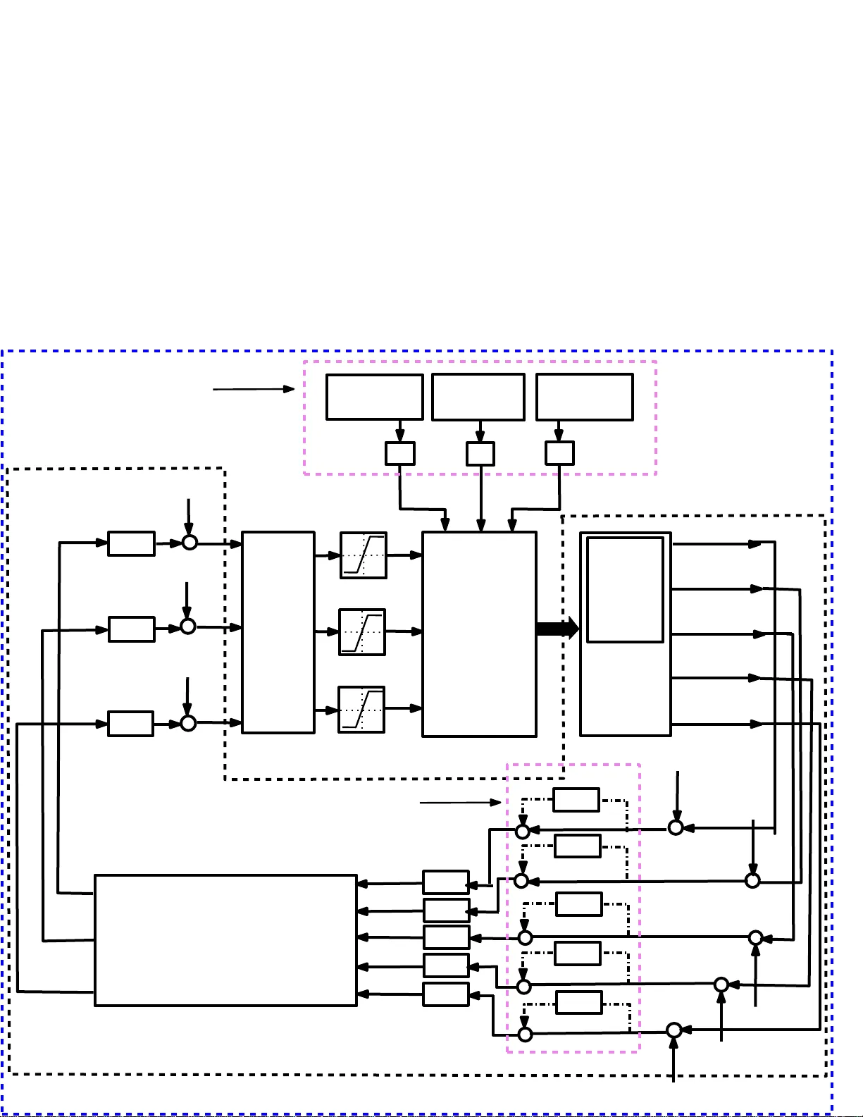
This paper has been accepted for publication in IEEE TRANSACTIONS ON SYSTEM, MAN , AND CYBERNETICS: SYSTEMS DOI: 10.11 09/TSMC.202 0.3012507 IEEE Xp lore: http s://ieeexplore.ieee.o rg/document/9166758 @2020 IEEE. Personal use of this material is permitted. Permission from IEEE must be obtained for all oth er uses, in any current or future media, inclu ding reprintin g /republishing this material for advertising o r p romotio nal purposes, creatin g ne w collective works, for resale or redistribution to servers or lists, or reuse of any c o pyrighted componen t of this work in other works. IEEE TRANSACTIONS ON SYSTEM, MAN, AND CYBERNETICS: SYSTEMS, V OL. XX, NO. XX, XXXX 2020 1 Rob ust Simultaneously Stabilizing Decoupling Output F eedback Controllers for Unstable Adv ersely Coupled N ano Air V ehicles Jinraj V . Pus h pangatha n, Harikumar Kan d ath, Member , IEEE, , Suresh Sunda ram, Senior Member , IEEE, , and Narasimha n Sundararajan, Life F ellow , IEEE Abstract —The plants of nano air vehicles (NA Vs) are generally unstable, adversely coupled , and u n certain. Besides, the autopilot hardwar e of a NA V has limited sensing and computational capabilities. Hence, these vehicles need a single controller r eferr ed to as Rob ust Simultaneously Stabilizing Decoupling (RS SD) out- put feedb ack controller that achieves simu ltaneous stabilization, desired decoupling, robustness, and perf orma nce f or a fin ite set of unstable mult i-input- multi-output adversely coupled u n certain plants. T o synth esize a RSSD outp u t feedback contr oller , a new method that i s based on a central plant is p roposed i n this p aper . Giv en a finite set of plants f or simultaneous stabilization, we considered a plant in this set that has the smallest maximum v − gap metric as the central plant. Following this, the sufficient condition for the existence of a simultaneous stabilizin g controller associated with such a plant is describ ed . The decoup l ing feature is then appen ded to th is controller using the p roperties of the eigenstructure assignment method. Afterward, the sufficient conditions fo r the existence of a RSS D output feedback controller are obtained. Using these suffi cient conditions, a new optimization problem fo r the synthesis of a RSS D outpu t feedback controller is formulated. T o solv e th is optimization problem, a new genetic algorithm based offline iterativ e algorithm is developed. The effectiv eness of this iterative algorithm is th en demonstrated by generating a RS SD controller for a fixed-wing nano air vehicle. The perform ance of this controller is validated through numerical and hardware -in-the-loop simulations. Index T erms —Decoupling, central plant, nano air vehicle, output feedback, robust simultaneous stabil ization, v -gap metric I . I N T R O D U C T I O N Nano air v ehicles are e xtremely small air vehicles that are widely used for intelligence, b a ttlefield surveillanc e and reconn a issanc e , and disaster assessment m issions. NA Vs have se vere dim ensional an d weight constrain ts as their overall dimension and weight need to be lower than 75 mm and 20 g, respectively [1]. Based o n flight modes, they are classified as fixed-win g , ro tary-wing , and flapping-win g NA Vs. Figu r e 1(a) shows a typical fixed-wing N A V that weighs 19.4 g and h a s an overall dimension of 75 mm. Ge n erally , a fixed- wing N A V re quires flig ht controller s to accomp lish a m ission. Researc h fello w @ Department of Aerospace Engineering, Indian Institute of Science, Bangalore-56001 2, India, e-mail: (jinrajaer o@gmail.com). Assistant Professor @ Robotics Resea rch Center , Internati onal Institute of Information T echnology , Hydera bad-32, India, e-mail :(harik umar .k@iiit.ac.in) Associate professor @ Department of Aerospace Engineering, Indian Insti- tute of Science, Bangalo re- 560012, India, e-mail: (vssuresh@iisc.a c.in). Professor (Retd.) @ School of Electrical and Electronic s Engi- neering , Nanya ng T ec hnologic al Uni ver sity , Singapore, e-mail: (ensun - dara@nt u.edu.sg). Note that in th is pap er , plan t re presents plant mod el . In m o st cases, one d esigns these flight contro llers based on linear time-inv a r iant (L TI) plan ts that are obtained b y linear iz in g the n onlinear plants o f a N A V abou t the nomin al trajec- tory associated with different steady -state fligh t cond itions. Thereafter, these controllers are scheduled (gain scheduling) based on the a ltitu de and Mach number (scheduling variables) to control th e n onlinear p lant. For example, in [ 2], a g ain scheduled controller fo r trajectory tr acking is sy n thesized for a fixed-wing unmann ed aerial vehicle (UA V). Becau se of the weight an d d imensional co nstraints, the autop ilot hardware of a NA V has se vere resource con straints as it lacks lightweigh t sensors to measu re state variables like an an gle-of- attack, airspeed, and sideslip angle. Also, N A V’ s autopilot hardware does not possess sufficient comp utational and memory powers. Figure 1(b ) shows a typica l autopilot ha rdware of the 7 5 mm wingspan fixed- wing N A V [3]. T h is auto p ilot weig hs 1. 8 g and has no sensors to m easure airspeed, angle-o f-attack, and sideslip an gle. (a) Fixe d-wing NA V (b) Autopilot hardware Figure 1 : 7 5 mm wingspa n N A V and autopilot hardware Besides, this autopilot h ardware has only 1 MB o f memo ry capacity . Due to th e insufficient compu tational an d memo r y powers, it is ha r d to implemen t the widely used e stima tio n algorithm , n a m ely , th e Extended Kalm an Filter (EKF) on N A V’ s autopilot hard ware. As airspee d cannot be measured or estimated , the Mach num ber will not be av ailab le for th e scheduling o f c ontrollers. Hen ce, gain sche d uling beco mes inappro priate for the NA V . Generally , the controller for an aircraft is designed u sing fu ll state feedback. For instance, in [4]-[5] and [6], a f u ll state feedb ack controller is de signed for a qua d copter and a micr o aerial veh ic le , respectively . Howev er , the flight contr o ller design using f ull state feedb ack becom es ineffecti ve for the NA V as all the state variables cannot be measured o r estimated . The multi-inp ut-multi-o utput (MIM O) L TI plants of a fixed-win g NA V are gene rally unstable becau se IEEE TRANSACTIONS ON SYSTEM , MAN, AND CYBERNET ICS: SYSTEMS, VOL. XX, NO. XX, XXXX 2020 2 of significan t ad verse c o upling (m ainly due to the notable gyrosco p ic co upling and co unter to rque of the p ropulsion unit), d imensional constraints on the stabilizer s, aer odyn a mic effects, and due to the limitation in keep ing cen ter-of-gravity (CG) at the desired location [3], [7]. The significant ad verse coupling also makes the successiv e loop closure auto pilot design techniq ue ill-suited for a fixed-wing NA V . Furth er , the autopilot design using the d istributed con trol system a p proach [8] becomes unsu itable due to adverse co upling and unavail- ability of sch eduling variables. Besides this, the presen c e of cou pling in the dy n amics makes various existing well- proven wayp oint following algorithms un suitable for a fixed- wing N A V as these alg o rithms are developed by con sidering a decoup led lon gitudinal and lateral dynamic plants. Hence, for u sing th ese algor ithms, the flight contro ller needs to have a m ode deco upling capability . Furthermor e , th e plan ts of a fixed- wing N A V have significan t un certainties ma inly due to the un steady flow , wind ef fect, un modeled dyna mics, and inaccur ate m easurements of forces and momen ts. The considerab le un c e rtainties in the plant cause no table errors in the estimation of state variables. Also, the unmo deled d ynamic uncertainty makes a linear q uadratic regu la to r (LQR) design unsuitable for a fixed-wing NA V . Besides gain schedulin g, the co n troller design tech n iques employed to design the flight controller for a nonlinear p lant of small aircraft a r e feedback linearization [9], back stepping with sliding mod e c o ntrol [10], and model referen c e ad aptive contr ol [11]. Howe ver , it is difficult to implement the se con trollers in a NA V due to the absence of high-ban dwidth actuator s and lightweigh t au topilot hardware with sufficient co mputatio n al power and suitable sensors. In g eneral, MIMO L TI plants of a fixed-wing NA V are unstable, adversely co u pled, and u ncertain [12]. These general c h aracteristics of the L T I pla n ts and the resource constraints of au topilot har d ware suggest that a NA V requ ir es a sing le c o mputatio n ally simple multiv ariable output feedback controller that pr ovides the simultan eous stabilization, desired decoup ling, r obustness, and performa nces to all the plants. The determ ination of a sin gle con troller tha t stabilizes a finite n umber of pla n ts is referre d to as th e simu ltaneous stabilization ( SS) p roblem . A simultaneo usly stabilizing con- troller is suitable for a NA V as it needs a single controller tha t stabilizes a finite n umber o f L TI plants. The SS pr oblem was first stud ied in [ 13] and [14]. T h ere is no tractab le solution to the SS pr o blem of mo re than two p lants due to its NP-h ard nature [15]-[1 6]. Hence, for these cases, th e SS pr oblem is solved thro ugh nu merical mean s. In [17], an iter ativ e algor ith m based on lin ear m atrix inequalities is d ev eloped to solve the SS problem of a finite set o f strictly p roper MIMO plants using static fu ll state feedback and output feedb ack. A decomp o sition strategy to solve the SS prob lem was propo sed in [18 ]. He re, a bi-lev el d esign o ptimization stru cture is selected in wh ic h the de sign of the sing le contr o llers f o r each plant is carried o ut at the botto m level, where as at the top-level op timization ge n erates a single co ntroller wh ic h can approx imate all those in dividual controller s. Further so lutions to th e SS problem emp loying optimiza tio n techniqu es ca n b e found in [19]-[22]. The SS p roblem can also be solved by first deriving a sufficiency condition associated with a central plant and then synthesizing a controller that satisfies this suf ficiency condition using robust stabilization tec h niques. This method is followed in [ 23]. Here, the central plant is obta in ed b y solving a 2-block optimization problem. In [2 4], a ce ntral plant which is the best appr oxima tion ( closest plant) to all the plants th at require SS is iden tified. The n, the suf ficient co n dition for the existence of a simultan eous stabilizing controller associated with this c e ntral p lant is o b tained using th e robust stabilization condition of a c oprime factorized plant an d v − gap m etric. Follo wing this, a stabilizin g controller that satisfies this cond i- tion is synth esized. It is to be noted that the afore mentioned methods do not gene r ate a single controller that concu rrently achieves simu ltaneous stabilization, ro bustness, perfo rmance, and d ecouplin g . The pr oblem of find ing a single output fee d back con troller that provides simultaneou s stabilization , desire d decoup ling, robustness ( against parametric and unmodeled dynamics un- certainties), an d perfo rmances to a finite set of plants is considered as a Robust Simultaneou s Stabilization Decoup ling (RSSD) pr o blem. I n this pape r, a RSSD p roblem is fir st formu late d for a finite set of MIMO L TI unstable adversely coupled uncertain p lants of a fixed-wing N A V and then th e same is solved in two step s. In the first step, the sufficient con- ditions f or th e existence o f a robust simultaneo us stabilizing output fe edback contr o ller associated with the central plant are obtained usin g r obust stabilization theory and the p roperties of the v -gap m e tric. Next, an outpu t fee d back decoup ling controller th at solves these cond itio ns is synthesized using the eigenstructu re assignm ent techniqu e . The main c ontributions of this paper are 1) As per the author’ s knowledge, this is the first time an output feedback co ntroller design m e thod th at p r ovides simultaneou s stabilization , desired decoupling , ro bust sta- bility , and per f orman c e s is prop osed. Besides, the pr o- posed method is gen eric as it can be app lied to a finite set of MIMO plants, minimum/n on-min imum phase plants, tall or fat plants, stable or un stable plan ts. 2) The sufficient con d itions for th e existence of a RSSD output fee d back contro ller are dev eloped using the robust stabilization conditio n of the righ t co p rime factorize d plant, th e p roperties of v -g ap metr ic, and the eigenstruc- ture assignm ent algo rithm for o utput f eedback. 3) Utilizing the sufficient con ditions, a new genetic algo - rithm b ased o ffline iterative algorithm called NN-RSSD (non- conv ex-non-smooth-RSSD) is developed to solve a RSSD p roblem. 4) The effecti veness of NN-RSSD algorithm is d emonstrated by gen erating a RSSD ou tput feedba ck controller for eight MIMO L TI unstable adversely coup led uncer tain plants of the fixed- wing NA V men tio ned in [3]. The perfor mance o f this designe d contro ller is then demon- strated first u sing six-d egree-of-f reedom sim u lations. The implementatio n aspe cts, especially of the auto pilot im- plementation , have been demonstrated using hardware-in- the-loop simulations of the closed-loo p (CL) nonlin ear plants of the NA V . The paper is organized as follows. In Section II, pr e liminar- IEEE TRANSACTIONS ON SYSTEM , MAN, AND CYBERNET ICS: SYSTEMS, VOL. XX, NO. XX, XXXX 2020 3 ies are giv en. The synth esizing of a RSSD outp ut feedback controller for a fixed-wing NA V is explained in Section III. In Section IV, the design and perf ormanc e e valuation of a RSSD outp ut feed back controller for the fixed-win g N A V is presented. Fina lly , in Section V, the conclusions are gi ven. I I . P R E L I M I NA R I E S Definition II.1 . Generalized stab ility ma r gin ( b P , K ∈ [0 , 1] ): Given a plant, P ( s ) and its contro ller , K . If th e CL plant , [ P ( s ) , K ] is internally stable, then [25] b P , K = 1 / h P ( s ) I i ( I − KP ( s ) ) − 1 [ − I K ] ∞ (1) otherwise, b P , K =0. Definition II.2 . v − ga p metric: Given two plants, P 1 ( s ) and P 2 ( s ) . T h en, v − gap metric, δ v ( P 1 ( j ω ) , P 2 ( j ω )) ∈ [0 , 1] of P 1 ( s ) and P 2 ( s ) is defined as [26] if det( I + P 1 ( j ω ) P 2 ( j ω )) 6 = 0 ∀ ω and wno det( I + P 2 ( j ω ) P 1 ( j ω )) + η ( P 1 ( j ω )) − η ( P 2 ( j ω )) − η 0 ( P 2 ( j ω )) =0, then δ v ( P 1 ( j ω ) , P 2 ( j ω )) = k Ψ( P 1 ( j ω ) , P 2 ( j ω )) k ∞ otherwise δ v ( P 1 ( j ω ) , P 2 ( j ω )) = 1 (2) where Ψ( P 1 ( j ω ) , P 2 ( j ω )) is (( I + P 2 ( j ω ) P ∗ 2 ( j ω )) − 0 . 5 ( P 1 ( j ω ) − P 2 ( j ω ))( I + P 1 ( j ω ) P ∗ 1 ( j ω )) − 0 . 5 ) . Definition II .3 . Central plant: Giv en a fin ite set, P . T hen, the central p lant b elongs to P has the smallest m aximum v − gap metric am ong the m aximum v − g ap metrics of all the plan ts in P [24]. In this paper, the centr a l plant of a set is den oted by sub script ‘ cp ’ . I I I . D E S I G N O F A R O B U S T S I M U LT A N E O U S S TA B I L I Z I N G D E C O U P L I N G C O N T RO L L E R F O R A F I X E D - W I N G N A V A fixed-wing NA V is developed to operate in a remotely controlled mode for surveillance witho ut gettin g detec ted by r adar . Therefo re, the NA V needs to be stabilized in all operating conditions and hence requires a flight co n troller . This section e xplains the synthesizing of a RSSD o u tput feedback controller for a finite set o f L TI M IMO unstable adversely coupled u ncertain plan ts of a fixed-wing N A V . A. F ixed -W ing N A V Dynamics an d the Pr oblem Sta tement T y pically , an aircraft dy namics is rep resented b y a set of continuo us nonlin e a r first-order differential equa tions given by ˙ X = f ( X , U ) (3) where X is th e state vector , U is th e inpu t vector, and f ( · , · ) is a no nlinear vector function describing th e d ynamics. T he control system d esign and stability analy sis of an aircr aft using these n onlinear eq uations ar e co mplex. Instead, an aircraf t’ s L TI plan ts are used for the contro l system design and stability analysis. The se L TI plan ts are obtain ed by lin e arizing the nonlinear equations g iv en in (3) about a nominal trajectory as- sociated with various steady- state fligh t co nditions. Th e above mentioned linear plants captur e the appr oximate behavior o f the no n linear plant in the neighbo rhood of a trim/equilibr ium point belongin g to th e n ominal trajectory . Furth er , the linear plant of an aircr a ft is decou pled into two, na mely , lin ear longitud inal a nd lateral mod els, wh en the gyr oscopic cou- pling, aerody namic cross-co upling, and inertial coup ling in the dy n amics of an aircraft are negligibly small. These linear longitud inal and lateral mo dels in state-space f orms ar e giv en by ˙ x Lo f = A Lo f x Lo f + B Lo f δ Lo f (4) ˙ x La f = A La f x La f + B La f δ La f (5) where x Lo f ∈ R ˆ a , x La f ∈ R ˆ b , δ Lo f ∈ R ˆ c , and δ La f ∈ R ˆ d are lon gitudinal state vector , lateral state vector , longitudina l control vector, and lateral co n trol vector , respe ctiv ely . In (4)- (5), A Lo f ∈ R ˆ a × ˆ a , A La f ∈ R ˆ b × ˆ b , B Lo f ∈ R ˆ a × ˆ c , an d B La f ∈ R ˆ b × ˆ d represent system and c o ntrol matrices of the longitud inal and lateral state-space m odels, respec tively . The dynamics of a fixed-wing NA V has sig n ificant cross-cou pling due to the inertial, gyroscop ic, and aerody namic effects [3]. Because of this cross-cou pling, the longitud inal state variables have a sign ificant influence fr om the lateral modes. Similarly , the lateral state variables h av e significan t influence from the longitud inal modes. Due to the significant cro ss-coupling , the linear long itudinal and lateral mo dels given in (4) and (5), respectively , are not su itable. The suitable lin ear model for a fixed-wing NA V is the linear co upled model which is g iv en as ˙ x f = A f x f + B f δ f (6) where x f ∈ R ˆ n = [ x Lo | x La ] T , A f ∈ R ( ˆ n × ˆ n ) = " A Lo f A La Lo f A Lo La f A La f # , B f ∈ R ( ˆ n × ˆ m ) = " B Lo f B La Lo f B Lo La f B La f # , δ f ∈ R ˆ m = [ δ Lo | δ La ] T , ˆ n = (ˆ a + ˆ b ) , and ˆ m = ( ˆ c + ˆ d ) . Here, A La Lo f ∈ R ˆ a × ˆ b , A Lo La f ∈ R ˆ b × ˆ a , B La Lo f ∈ R ˆ a × ˆ d , and B Lo La f ∈ R ˆ b × ˆ c are the long itudinal cou pling b lock of A f , lateral coupling block of A f , long itu dinal cou p ling bloc k of B f , and later al cou pling blo c k of B f , respec tively . Along with cross-coup ling, if any λ i f ( A Lo f 0 0 A La f ) ∈ C − migrates tow ards C + due to the pr e sen ce of A La Lo f and A Lo La f in A f , then lin ear dy namics is ad versely coupled. Gen e rally , the linear dynamics o f a fixed-wing NA V is ad versely coupled . One suc h example is the 75 mm win gspan fixed-wing N A V m entioned in [3]. In [ 3], it is shown that λ 8 f ( A Lo f 0 0 A La f ) = − 0 . 112 becomes 0.951 due to the p r esence o f A La Lo f and A Lo La f in A f . Apart fro m the adverse co upling, all the linear plants associated with various steady -state fligh t conditions d efined in the flight en velope of this NA V are unstable with a d ifferent number of unstable po les [1 2]. Addition ally , the pr opeller effects, wind effects, sensors dynam ics are no t consider e d while developing the dynamic m o del of 75 mm wingsp a n fixed- wing NA V . Hence, the plan ts of this NA V have significant parametric and unm odeled d ynamic u ncertainties. Also, th e autopilot hardware of the fixed-wing NA V sh own in Fig. 1(b ) has resource co nstraints. Therefo re, to accomplish a mission, IEEE TRANSACTIONS ON SYSTEM , MAN, AND CYBERNET ICS: SYSTEMS, VOL. XX, NO. XX, XXXX 2020 4 this NA V requir es a RSSD o utput feed back flight controller as the gain sch e duling, full state feedback contro ller , successi ve- loop-clo sure, an d LQR do not suit. Now , to defin e the pro blem statement, let P f ( s ) ∈ RL ∞ ˆ r × ˆ m be the stabilizable L TI MIMO u n stable adversely coupled unc e rtain plant of a N A V . Here, RL ∞ ˆ r × ˆ m symbolizes the space of pro per, real-r a tional, ˆ r × ˆ m matrix-valued func- tions of s ∈ C wh ic h are analytic in C + ∪ C − . The state-spa ce form of P f ( s ) is giv en as ˙ x f = A f x f + B f δ f y f = C x f (7) where y f ∈ R ˆ r and C ∈ R ( ˆ r × ˆ n ) represent the output vector and output matrix, respectively . I n the above state-space model, the numb er of outputs is less than the numb er of state variables ( ˆ r < ˆ n ) as th e au topilot h ardware lacks sensors to measure ev ery state variables. Addition ally , the num ber of u nstable poles o f P f ( s ) and its u n certain plant is no t the same. W e n ow consider a finite set, P = { P 1 ( s ) , . . . P f ( s ) , . . . , P N ( s ) } ⊂ RL ∞ ˆ r × ˆ m contains the se stabilizable L TI MIM O un stable adversely c o upled u ncertain plants of a NA V . The unstable plants of P also have a d ifferent nu mber of unstable poles. The objective here is to find an o utput feedbac k co ntroller, K ∈ R ˆ m × ˆ r , that achieves the following for all the plants belongin g to P . 1) Robust sim u ltaneous stabilization . 2) Mo de de c o upling . 3) Spe cified per f ormanc e char acteristics. B. Simultaneo us Sta bilization with a Central P la nt The method conside r ed in this paper for simultaneo u sly stabilizing a finite set o f plants is to ach iev e a con tr oller that satisfies th e sufficient c ondition for the existence o f a simultaneou s stab ilizin g co ntroller assoc iate d with a central plant. Here, the sufficient condition giv en in [24] is employed. T o explicate this sufficient cond ition, let the m aximum v -g ap metric of P i ( s ) ∈ P , ǫ P i is given by ǫ P i = max δ v P i ( j ω ) , P f ( j ω ) P i ( s ) , P f ( s ) ∈ P ∀ f ∈ { 1 , 2 , . . . , N } (8) Follo wing this, let the set, ¯ ǫ con tains the maximum v -g ap metrics of all the plants in P . If P cp ( s ) is the central plant of P with a maximu m v -gap metric of ǫ P cp , th e n fro m the definition of centr al plan t, th e ǫ P cp = min ¯ ǫ . The reupon , the sufficient co ndition for th e existence o f a simu ltan eous stabilizing co ntroller associated with P cp ( s ) is giv en by [2 4] b P cp , K > ǫ P cp = min ¯ ǫ (9) T o solve (9), the id e ntification of P cp ( s ) and ǫ P cp is needed. This is acc o mplished by perfo rming v − gap met- ric an alysis that has the following steps At first, find th e values of maximum v − g ap m etrics of all the plants using max δ v P i ( j ω ) , P f ( j ω ) P i ( s ) , P f ( s ) ∈ P ∀ f ∈ { 1 , 2 , . . . , N } . Amo n g these values, the smallest value gives ǫ P cp . Also, the p lan t associated with th is value is the central plant. T h e detailed explan ation of the SS with a central plant is given in the supportin g mater ial. When the maxim um v − gap metric of the central plan t becomes smaller and closure to zero, similar closed- loop characteristics c a n be p r ovided to all plants in P using a simu ltan eous stabilizing con troller that satisfies (9) . The maximum v − gap metric of the centr al plant is reduced and the freque ncy characteristics o f th e plan ts in P is improved by cascad ing the se plan ts with suitable pre and post compen sators, W in ( s ) and W ot ( s ) , respectively [2 4]. The p roblem of si multaneou s red u ction of th e max im um v − gap metric of the cen tral plant an d the improvement of f requen cy char a cteristics of all p lan ts in P is term ed as the simultan eous closeness-pe r forman ce en hanced (SCP) problem . Let κ = ˜ P f ( s ) ˜ P f ( s ) ∈ RL ∞ ˆ r × ˆ m , ˜ P f ( s ) = W ot ( s ) P f ( s ) W in ( s ) , P f ( s ) ∈ P , W ot ( s ) ∈ RH ∞ ˆ r × ˆ r , W in ( s ) ∈ RH ∞ ˆ m × ˆ m , ∀ f ∈ { 1 , 2 , . . . , N } . No w , th e SCP problem is stated as the fo llowing. Find W in ( s ) and W ot ( s ) such that the following are ac hieved. 1) The max imum v − g ap metric of th e central pla n t of κ (SCP cen tr al plant) less than th e maxim um v − gap m e tr ic of the central p lan t of P . 2) W in ( s ) and W ot ( s ) induc e desired frequen cy character- istics on all the plan ts (p erform ance en hanced p lants) th a t belongs to κ . Let ˆ ǫ is defin ed as ˆ ǫ = max δ v W ot ( j ω ) P 1 ( j ω ) W in ( j ω ) , W ot ( j ω ) P f ( j ω ) W in ( j ω ) | ∀ f ∈ { 1 , 2 , .., N } , . . . , ma x δ v W ot ( j ω ) P N ( j ω ) W in ( j ω ) , W ot ( j ω ) P f ( j ω ) W in ( j ω ) | ∀ f ∈ { 1 , 2 , .., N } (10) Then, the optimizatio n prob lem to find the solutio n of the SCP problem is gi ven as [24] minimize Q J 1 = min ˆ ǫ subject to 1) Bound co nstraints on th e co efficients o f p r e and post compensators 2) No p ole-zer o cancellation between compensato rs an d the plants of P (11) In (11), Q r epresents the set that contains the coefficients of W in ( s ) and W ot ( s ) . T h e bo und constrain ts on the co- efficients of co m pensators ar e to pr ovide desired freq uency characteristics to the plants of P . These constraints prevent the minimizatio n of J 1 with any W in ( s ) and W ot ( s ) that degrade the freq u ency ch a racteristics o f all the augme n ted plants. The p e rforman ce index of (1 1) is no n-conve x and non- smooth. Hence, an iterativ e algorithm is req uired to obtain a so lution. Note that the pre/p ost compen sators are p hysically present in the clo sed-loop . Ther efore, these com p ensators need to be appended with the hardware. C. Ap pendin g Decou pling and Robustness F ea tur es to a Si- multaneou sly S tabilizing Outpu t F eedba ck Co n tr oller , K 1) Appen ding Decoup ling to K : T o explain the method that ap pends decou pling features to K , let us consider W in ( s ) and W ot ( s ) as the solution of (11) and ˜ P cp ( s ) = IEEE TRANSACTIONS ON SYSTEM , MAN, AND CYBERNET ICS: SYSTEMS, VOL. XX, NO. XX, XXXX 2020 5 W ot ( s ) P i ( s ) W in ( s ) as the SCP central plant with maximum v − gap m e tric of ¯ J 1 . Let the generalize d stab ility margin of ˜ P cp ( s ) is giv en as b ˜ P cp , K = 1 / h ˜ P cp ( s ) I i I − K ˜ P cp ( s ) − 1 [ − I K ] ∞ (12) The sufficient conditio n associated with ˜ P cp ( s ) for the SS is giv en as b ˜ P cp , K > ¯ J 1 (13) The cond ition given in (13) is achieved by minimizing the infinity norm of b ˜ P cp , K using a finite number of stabilizing output f eedback contro llers of ˜ P cp ( s ) . T o solve a RSSD problem , these controllers need to provide desired mode de- coupling to the CL plants besides minimizing the infinity norm. Eigenstructu re assignment is a well kn ow linea r co ntroller design tech nique that assigns the desired CL eigen values and eigenv ectors. Using this technique, the modes o f a dynam ic system can be decouple d from th e state variable respo nses by assign ing ze r o v alue to the cross-coup led eigenvector elements o f the desired eigenv ectors. Follo wing the eigenstru c- ture assignm ent techn ique described in [27], ˆ r desired CL eigenv a lu es and ˆ m entries of the cor r espondin g eigen vectors are assigned with the o utput feedback controller , K ∈ R ˆ m × ˆ r giv en by K = W ( C R ) − 1 (14) where C denotes the outpu t matrix of ˜ P cp ( s ) . W = [ W 1 , . . . , W l , . . . , W ˆ r ] and R = [ R 1 , . . . , R l , . . . , R ˆ r ] are defin ed as if λ l is real, then R l W l ∈ { S l : A − λ l I B R l W l = 0 } if λ l is com plex, then R l W l ∈ { S l : A − λ r e l I λ im l I B 0 − λ im l I A − λ r e l I 0 B R r e l R im l W r e l W im l = 0 } (15) where R l = [ R r e l | R im l ] T and W l = [ W r e l | W im l ] T when λ l is complex. Furthermo re, in (15), A and B represent system and inpu t matrices of ˜ P cp ( s ) , respectively . Also, λ l , λ r e l , and λ im l denote l th d e sired eige n value, re al p art of th e l th desire d eigenv a lu e, and imag inary pa rt of the l th desired eigenv alue, respectively . R l and W l are computed using specific v alues assigned to ˆ m entries of eigenv ectors associated with a desired CL eigenv alue. For d e coupling , these ˆ m entries are assigne d with z e ro value. The contro ller K given by (14) dep ends on the allowable eigenv ector spac e [27]. This e ig en vector space depe nds on the desired CL eigenv alues, system , inpu t, and output ma tr ices of the plan t. For the given desired CL eigenv alues and eigen - vectors, a sing le K is obtained . Howe ver, a single K do e s not minim ize the in finity nor m giv en in (12). This issue is solved using the following a p proach . Usually , the desired CL eigenv a lu es are selected based on specific characteristics. For example, one such charac teristic is the damping ratio. I f the desired CL eigenv alues require a damping ratio greater th an or equal to ζ de , then these eigenv alues lie in a region d efined by the constant dampin g ratio line. Following this, a region, S 1 in C − is pr e defined using th e specific characteristics required for the desired CL eigenv a lues. Ther e will be an infin ite num ber of desired CL eigenv alues in this region. Now , obtain the K using a search and m inimization algorithm that perfor ms the following f unction s. 1) Search in S 1 and obtain the desire d CL eigenv alues, λ l ∈ S 1 ∀ l ∈ { 1,2, . . . , ˆ r } . 2) Compute K = W ( C R ) − 1 using the desired CL eigenv al- ues f rom S 1 . 3) Check whether K = W ( C R ) − 1 stabilizes ˜ P cp ( s ) . For this purpo se, examine whether the remaining n − ˆ r ( n is the nu mber of states of ˜ P cp ( s ) ) CL eigenv a lu es, λ i ∀ i ∈ { ˆ r +1, ˆ r +2,. . . , n } , are in S 1 . If λ i ∈ S 1 ∀ i ∈ { ˆ r +1, ˆ r +2,. . . , n } , then K = W ( C R ) − 1 stabilizes ˜ P cp ( s ) . Therefo re, if λ i ∈ S 1 ∀ i ∈ { ˆ r +1, ˆ r +2,. . . , n } , then go to 4. Other wise, go to 1. 4) Minimize infinity norm given in (12) usin g K . 5) Repeat 1, 2, 3, an d 4 u ntil K satisfies th e sufficient condition f or SS gi ven in (13). In b rief, if th e search and m inimizing alg orithm obtains a K = W ( C R ) − 1 that achieves ( 13) with all λ ( A + B K C ) ∈ S 1 , then K provid es desired d ecouplin g to the CL plan t of ˜ P cp ( s ) and SS to all the plants in κ . Note that even with this K , when the CL char acteristics of ˜ P cp ( s ) and the CL character istics of remaining plants of κ are dissimilar , then a new solution for the SCP prob lem is r equired . This solution need s to p rovide a new ˜ P cp ( s ) with a maximu m v − gap metric that should be less than the p r evious ¯ J 1 . Th is is be cause the CL characteristics of ˜ P cp ( s ) an d the remainin g plants of κ will be similar whe n ¯ J 1 of ˜ P cp ( s ) gets closer to zero. Remark III.1 . Th e term inside the infinity no rm of (1 2) is the CL tr ansfer f unction o f ˜ P cp ( s ) from exogeno us inp uts to contr olled variables. Hence, minimizin g the infinity n orm also impr oves tracking perfo rmance, d isturbance rejection , and noise rejection o f the CL plant. Follo wing this, if the maximum v − gap metric of ˜ P cp ( s ) is closer to zero, then the closed- loop perfo r mance characte r istics o f all the plants in κ will be similar to the closed-loo p perfo rmance characteristics of ˜ P cp ( s ) achie ved by minimizing the infinity norm o f (12). 2) Appen ding Robustness to a Simultan eously Stab ilizing Decouplin g Output F eedback Contr oller , K : An output feed- back con troller, K = W ( C R ) − 1 that satisfies (1 3) a c c om- plishes SS and deco upling . Besides th is, an RSSD outp ut feedback c ontroller needs to provide robustness to each plants belongin g to κ . Th e concept of ro bust SS is illustrated in Fig. 2 . This figure suggests that a single con troller must simultaneou sly stab ilize all plants belon ging to κ , but also need to stabilize each plan t aga inst certain normalized r ig ht coprime factor pertu r bations. W e now propo se the following lemma that illustrates the robustness featur es o f a simultaneo u s IEEE TRANSACTIONS ON SYSTEM , MAN, AND CYBERNET ICS: SYSTEMS, VOL. XX, NO. XX, XXXX 2020 6 stabilizing d e coupling con tr oller . K = W ( C R ) − 1 M − 1 ˜ P f ( s ) N − 1 ˜ P f ( s ) ∆ M ˜ P f ( s ) ∆ N ˜ P f ( s ) − + + + ˜ P f ( s ) ∈ κ ∀ f ∈ { 1 , . . . , N } Simultaneous stabilization Robust simultaneous stabilization Figure 2 : Co ncept of rob ust simultaneous stabiliza tion Lemma III.1 . L et W an d R ar e ch osen for achieving th e desired decoup ling. Then, the output feedback controller, K = W ( C R ) − 1 , of ˜ P cp ( s ) accomp lishes r o bust simultaneo us stabilization o f N p lants b elongin g to ξ = ˜ P ( s ) ˜ P ( s ) ∈ κ, δ v ( ˜ P cp ( j ω ) , ˜ P ( j ω )) ≤ ¯ J 1 ˜ P cp ( s ) ∈ κ and p rovides exact desired d ecouplin g to the CL p la n t of ˜ P cp ( s ) , if th e f ollowing condition s ar e satisfied. [1] λ l ∈ S 1 ∀ l ∈ { 1,2,. . . , ˆ r } [2] λ i ∈ S 1 ∀ i ∈ { ˆ r +1 , ˆ r +2,. . . ,n } [3] b ˜ P cp , K > ¯ J 1 Pr oo f. K stabilizes ˜ P cp ( s ) when the conditions [ 1 ] and [2] are met. Concu rrently , K provides exact d esired de coupling to ˜ P cp ( s ) an d simultaneo usly stabilizes N plan ts belon ging to ξ when K achieves all three con ditions. No w to prove K achieves robust simultaneou s stabilization of N plan ts, let us define th e ball of plants, B ( ˜ P cp ( s ) , ¯ J 1 ) , as B ( ˜ P cp ( s ) , ¯ J 1 ) = ˘ P ( s ) δ v ˜ P cp ( j ω ) , ˘ P ( j ω ) ≤ ¯ J 1 , ˜ P cp ( s ) ∈ ξ , ˘ P ( s ) ∈ RL ∞ ˆ r × ˆ m (16) When K satisfies all the three condition s, any plant belongin g to ∂ B (boun d ary of B ( ˜ P cp ( s ) , ¯ J 1 ) ) is also stabilized by K as v − gap metrics between the p lants b elonging to ∂ B and ˜ P cp ( s ) are ¯ J 1 . v − gap metrics b etween ˜ P cp ( s ) and the plants in I nt ( B ) (interio r o f B ( ˜ P cp ( s ) , ¯ J 1 ) ) ar e less than ¯ J 1 as ¯ J 1 is th e max imum v − gap m e tr ic of ˜ P cp ( s ) . There- fore, K simultan eously stabilizes all the plants b elong to B ( ˜ P cp ( s ) , ¯ J 1 ) if the con ditions [1], [2], and [3] are met. As ξ ⊂ B ( ˜ P cp ( s ) , ¯ J 1 ) , K simultaneou sly stab ilizes all the N plants. Even if a ny pla n t, ˜ P ( s ) ∈ ξ is pertu rbed to form the plant, P ( s ) ∈ B ( ˜ P cp ( s ) , ¯ J 1 ) \ ξ is also stabilized by K . Therefo re, K achiev es ro bust simultaneou s stabilization of N plants belo nging to ξ . This establishes the proof. The three condition s of Lemma III.1 imply sufficient con di- tions for the existence of a RSSD output f eedback controller . Moreover , the stru cture of ξ sugg ests any K that satisfies the three c o nditions o f Lemm a III .1 also achieves robust simultaneou s stabilization of N plants of P . D. NN-RSSD Alg o rithm An itera ti ve algor ith m is req uired f o r solving a RSSD problem d ue to th e NP- hard nature of output f eedback an d SS problem s. The controller generated by the iterativ e algo rithm becomes the solu tion o f a RSSD pro blem onc e th is contro ller satisfies three cond itions of L emma III .1. Using these con - ditions, we n ow recast a RSSD pro blem as an optimizatio n problem th at is gi ven as minimize K J 2 = ˜ P cp ( s ) I I − K ˜ P cp ( s ) − 1 − I K ∞ s.t. λ l ∈ S 1 ∀ l ∈ { 1,2,. . . , ˆ r } K = W ( C R ) − 1 λ i ∈ S 1 ∀ i ∈ { ˆ r +1, ˆ r +2,. . . ,n } (17) The solution of a RSSD pro blem is a K ∈ R ˆ m × ˆ r that reduces J 2 below ¯ J 1 with all the constraints of (17) satisfied. A gen etic algorithm based of fline iter ativ e alg orithm refer red to as th e NN-RSSD algorithm is developed f or sequentially solving the optimization pro blems associated with the SCP proble m and the RSSD problem . The genetic a lgorithm is employed in the iterativ e alg orithm as the o ptimization problem associated with the SCP pro blem is non-convex an d non-smooth. At first, the NN-RSSD algorithm solves the optim ization p roblem of th e SCP pro b lem g i ven in ( 11). Then, the op timization problem of the RSSD pro blem given in (17) is solved u tilizing th e solution of the SCP pr oblem. For this pu rpose, the NN-RSSD algorithm has two po p ulation-b ased genetic algorithm (GA) solvers, namely , GA-SCP an d GA-RSSD. GA-SCP solves the optimization pro blem of the SCP p roblem , wher eas GA-RSSD solves the optimization prob lem o f the RSSD problem. In GA- SCP an d GA-RSSD, GA employs the following steps. 1) Randomly g enerate initial v alues of search variables. 2) Compute the v alue of fitn e ss function using the fe a sible values am ong the v alues of search variables. 3) Generate n ew values o f searc h variables by examining the fitness value o f search variables and apply ing g e n etic operator s o n the v alues of search variables. 4) Repeat 2 and 3 until the stopping criterion is satisfied. Sear ch V ariables: The search variables of GA-SCP are the coefficients of W ot ( s ) an d W in ( s ) . T h e feasible v alues of these sear ch variables are tho se which satisfy all the constraints of the prob lem given in (11). In the NN-RSSD algorithm , th e ch osen desired eigenvector element for mo de decoup ling is not assigned a ze ro value, but it is confined in a bound ed set and used as a search variable b y GA-RSSD. This reduces the failure o f the eigenstru cture assign ment algor ithm in computing the contro ller gain using (14) when all the chosen desired eigenvector elements are assigned with zer o value. Further, the av ailability o f the chosen desired eige n vector element as search variables contributes ad ditional freedom in the com putation of th e contr oller defined b y (14). The b ound on a ch osen desired eigenvector elemen t is determine d by th e magnitud e o f un fa vorable do minance of a mode on the state variable. Also, the search variables of GA-RSSD includ e ˆ r desired CL eigen v alues. The feasible values o f ˆ r eigenv alues IEEE TRANSACTIONS ON SYSTEM , MAN, AND CYBERNET ICS: SYSTEMS, VOL. XX, NO. XX, XXXX 2020 7 and chosen desired eig en vectors are those belon ging to S 1 and the user -defined b ound ed set, respectiv ely . F itne ss function s: The fitness function of GA-SCP is th e perfor mance in dex, J 1 , of the op timization problem gi ven in (11). The fitness function of GA-RSSD is the perfo r mance index, J 2 , o f the optimization pr oblem given in (17). T ermination Con ditions: The NN-RSSD algo rithm termi- nates wh en the number of generation of GA-SCP exceeds its maximum v alue or wh en GA- RSSD generates a f e asible RSSD output feed back con troller . The work ing of the NN- RSSD algo rithm is explained as follows. At first, GA r andom ly o btains the in itial values of the search variables of GA-SCP . Th e n, the fitness f unction of GA-SCP is evaluated, as shown in Algorithm -1. Durin g this fitness evaluation, if the obtained solution satisfies an adaptive constraint, then the GA-SCP inv okes GA- RSSD and p asses ˜ P cp ( s ) and its maximu m v − gap metr ic to the GA-RSSD. The adaptive constraint employed here is fitness v a lue of GA-SCP < ¯ J 1 . During the fitness fun c tion ev aluation of the GA-RSSD, if the value of the fitness function satisfies the cond ition, J 2 < 1 ¯ J 1 , then that controller becomes the feasible controller . Thereafter, the NN-RSSD algorithm terminates. When the GA- RSSD could not find a feasible contr oller for a ˜ P cp ( s ) , then ¯ J 1 is assigned with the fitness value that previously satisfi ed the adaptive constraint. Note that, n ew ¯ J 1 < old ¯ J 1 enables GA-SCP to search f or n ewer ˜ P cp ( s ) that has a maximum v − gap metr ic which is less than new ¯ J 1 . This enh a nces the possibility of obtaining a feasible RSSD outpu t feedb ack controller . During the fitness evaluation of GA-SCP , if the solution obtained d oes no t satisfy an adaptive co nstraint, then GA searche s for n ew feasible values. Note that fo r computing K requ ires the inv erse of C R . I f the co ndition number of C R , κ ( C R ) , is infinity , then C R singular . Follo wing th is, the existence o f the in verse of C R is g uarantee d by satisfying the condition , κ ( C R ) < 10 5 . If this condition is satisfied, then compute K = W ( C R ) − 1 else GA obtain n ew f easible values of GA-RSSD’ s search variables. The pseu docod e o f the NN- RSSD a lg orithm is gi ven in Algorithm- 1 and Algorithm-2 . I V . D E S I G N A N D P E R F O R M A N C E E V A L UAT I O N O F T H E R S S D O U T P U T F E E D B A C K C O N T RO L L E R F O R A F I X E D - W I N G NA V This section d iscusses the design of a RSSD output f e edback controller using the NN-RSSD algorith m for eig ht unstable MIMO ad versely coupled plants of the NA V men tioned in [3]. More details about the n onlinear and line a r p lants of th e N A V , desired eige nvector elements, and bound s of pre/po st compen sato rs are giv en in the supporting material. Am ong the output variables o f these pla n ts (pitch angle ( θ ), p itch rate ( q ), yaw rate ( r ), roll rate ( p ), and roll angle ( φ )), th e con tr olled variables are θ and φ . The f requen cy char acteristics of the e ight plants req u ire modification s as they d o not have the desired characteristics. T o inco rporate necessary frequ ency character- istics on the output sensiti vity function, we req uire W ot ( s ) and W in ( s ) that satisfy σ ( W ot ( 0 ) P f (0) W in ( 0 )) > 6 d B and σ ( W ot ( j ω ) P f ( j ω ) W in ( j ω )) > 0 dB up to the desired frequency for all f ∈ { 1 , 2 , . . . , 8 } . Here, the desired frequen cy ranges from 1 5.28 rad/s to 53.3 r a d/s. P 2 ( s ) amo ng the eight plants is iden tified as the central plant as it has the smallest max imum v − gap metric of 0.4 489 ( min ¯ ǫ ). Algorithm 1 Pseudoco d e of NN-Algorithm 1: Input: P , ¯ J 1 , n , and ˆ r 2: if num ber of g eneration of GA-SCP ≤ m a ximum value then 3: GA obtain feasible values of GA-SCP’ s search v ari- ables 4: Compute: W in ( s ) and W ot ( s ) using ( 13)-( 16) given in [ 24]. 5: Compute: J 1 for fitne ss evaluation 6: if Fitne ss value < ¯ J 1 then 7: Obtain: ˜ P cp ( s ) by p erform ing v − gap m e tric anal- ysis on ξ 8: Set ¯ J 1 =Fitness v alue 9: G A - R S S D ( ˜ P cp ( s ) , ¯ J 1 , n , ˆ r ) 10: go to 2 11: else 12: go to 2 13: end if 14: e lse 15: Exit 16: e nd if Algorithm 2 Pseudoco d e of GA-RSSD 1: function G A - R S S D ( ˜ P cp ( s ) , ¯ J 1 , n , ˆ r ) 2: if numb er of gen eration of GA-RSSD ≤ maxim um value then 3: GA obtain feasible values of GA-RSSD’ s search variables 4: Compute: W an d R (using A and B of ˜ P cp ( s ) an d feasible values of search variables of GA-RSSD) 5: Compute: C R and κ ( C R ) 6: if κ ( C R ) < 10 5 then 7: Compute: K = W ( C R ) − 1 8: if λ i ( A + B K C ) ∀ i ∈ { 1 , 2 , . . . , n } ∈ S 1 then 9: Compute: J 2 for fitne ss ev aluation 10: if Fitness value < 1 ¯ J 1 then 11: Controller fo u nd ( K ) and Exit 12: else 13: go to 2 14: end if 15: else 16: go to 2 17: end if 18: else 19: go to 2 20: end if 21: else 22: return 23: end if 24: e nd function IEEE TRANSACTIONS ON SYSTEM , MAN, AND CYBERNET ICS: SYSTEMS, VOL. XX, NO. XX, XXXX 2020 8 A. Flight Contr ol System Design Specifi cations and Contr oller Gain Sy nthesis 1) Da mping Ratio Specifi cations: The min imum r equired damping ratios fo r a ll the oscillatory modes of the N A V are taken as 0.30. 2) T racking S pecificatio ns: The tracking error in the pitch angle and th e r o ll an gle of the NA V in the absence of wind distur bances concer ning the refer ence signal ar e ± 0 . 008 7 rad and ± 0 . 0175 rad, respe ctiv ely . Also, in the p resence of wind disturb a n ces, roo t mean square deviation (RMS) of the pitch a n gle an d roll an gle n e ed not exceed 0.0873 rad an d 0. 1 75 rad, respecti vely . 3) Ro bustness Requir ements: An uncertainty le vel of 40 % is assigned to all the static, d ynamic, an d con trol deriv a- ti ves o f the N A V . Concu rrently , for each CL plant, the controller h as to p rovide a multiloop disk -based g ain margin (MDGM) an d ph ase m argin ( MDPM) of ± 3 d B and ± 20 d eg, resp ectiv ely . 4) Desired eigen values a nd eigenvector s: Th e eigenv alues of the couple d spiral, coupled Dutch roll, an d coup le d short period m odes o f the NA V are a ssigned as these eigenv al- ues do not possess the desired stability and performan ce characteristics. For more details abou t these m odes an d their cou pling characteristics, o ne should ref er [3]. T he bound s on the cho sen desired eigen vector elements for mode decoupling are given in T able I. In T able I, ¯ u , ¯ w , ¯ r , ¯ p , and ¯ φ deno te the eige nvector e lem ents associated with the state variables, u ( tr anslational velocity in x body- axis), w (translational velocity in w body- axis), r , p , and φ , resp e ctiv ely . T ab le I : Boun ds on th e chosen desired eige n vector elemen ts Mode Eigenv ector Bound Element Coupled Spiral ¯ u, ¯ w, ¯ r ± 0.01 , ± 0.01, ± 0.01 Coupled Dutch ¯ p [ ± 0.04 9] ± [ ± 0.049 ] j roll ¯ φ [ ± 0.1] ± [ ± 0. 08] j Coupled Short ¯ r [ ± 0.01 5] ± [ ± 0.15] j period The NN-RSSD algorithm is executed with inputs, ˆ r = 5 , ˆ m = 3 , n = 19 , ¯ J 1 =0.448 9, P , the bound s on the coefficients of W ot ( s ) an d W in ( s ) , the boun ds on the chosen desired eigenv ector ele m ents, the maximu m numb er of gene r ations of GA-SCP (20) and GA-RSSD (1000), an d S 1 defined for the damping ratio of 0 . 3. NN- RSSD algorithm terminates at the 38 8th generatio n of GA-RSSD. Subsequ ently , the feasible compen sato rs are given as W in ( s ) = diag 1 . 0 s + 7 . 36 0 . 007 s + 10 . 1 , 14 . 71 s + 59 . 78 0 . 002 s + 0 . 099 , 0 . 992 s + 5 . 091 0 . 0053 s + 11 . 89 (18) W ot ( s ) = diag 0 . 61 s + 11 1 . 6 s + 1 . 6 , 0 . 23 s + 29 . 58 0 . 55 s + 0 . 36 , 0 . 813 s + 12 . 1 7 . 996 s + 1 . 46 , 0 . 91 s + 9 . 78 0 . 331 s + 0 . 342 , 0 . 78 s + 16 . 81 1 . 41 s + 1 . 0 (19) The feasible RSSD o utput feedback contro ller gain is given as K = 1 . 13 0 . 78 0 . 26 0 . 14 0 . 13 − 1 . 07 − 0 . 78 0 . 74 0 . 00 9 0 . 54 0 . 19 − 0 . 06 − 0 . 002 1 . 29 0 . 04 (20) Besides this, the SCP central plan t is ˜ P cp ( s ) = W ot ( s ) P 3 ( s ) W in ( s ) with the maximum v − g ap metric of 0. 3184. As this value is less than 0 .4489 , one o f the objectives of the pre a n d post comp ensators is achieved. The frequen cy c h aracteristics of ˜ P f ( s ) = W ot ( s ) P f ( s ) W in ( s ) for all f ∈ { 1 , 2 , . . . , 8 } are shown in Fig. 3. This figure 10 -2 10 0 10 2 10 4 Frequency (rad/s) -150 -100 -50 0 50 100 Singular value (dB) ˜ P 1 ˜ P 2 ˜ P 3 ˜ P 4 ˜ P 5 ˜ P 6 ˜ P 7 ˜ P 8 26 rad/s 41.33 rad/s 6 dB Figure 3 : Singular v alue plots of the plants . indicates σ ( ˜ P f (0)) > 6 dB for all f ∈ { 1 , 2 , . . . , 8 } . As illustrated in Fig. 3, the 0 dB cro ssing frequ encies of all the perfor mance enh anced plants are within the desired limit as the range o f 0 dB cr ossing frequencies o f σ ( ˜ P f ( s )) for all f ∈ { 1 , 2 , . . . , 8 } ar e within 2 6-41. 33 rad/s. Henc e , W in ( s ) and W ot ( s ) given in (18) and (19) satisfy all the design requirem ents with respect to the performan ce enhanced plants. B. Stability a nalysis The controller gain giv en in (20) simultaneo u sly stab ilizes eight p lants of th e NA V as all the eige n values of the CL plants, ˆ H f ( s ) = ˜ P f ( s ) K I − ˜ P f ( s ) K for all f ∈ { 1 , 2 , . . . , 8 } lie in C − as shown in Fig. 4. T his fig ure a lso in dicates the d amping ratios of all the CL eigenv alues are g reater than o r equ al to 0.3. Besides this, T a b le II suggest tha t all th e eight CL p lants have desired MDGM and MDPM. T h e parametric and un - modeled d ynamic uncerta in ties are represented by the inv erse input mu ltiplicative and outp ut multiplica tive unce rtainties, respectively . The tolerance le vel of the CL plants against the output multiplicative uncertain ty is analyzed using the plots of 1 σ ( ˜ P f ( j ω ) K ( I − ˜ P f ( j ω ) K ) − 1 ) for all f ∈ { 1 , 2 , . . . , 8 } de p icted in Fig. 5 . This figu re depicts that the o u tput multiplicative uncertainty tolerance levels increase with the frequen cy . Th is IEEE TRANSACTIONS ON SYSTEM , MAN, AND CYBERNET ICS: SYSTEMS, VOL. XX, NO. XX, XXXX 2020 9 −1200 −1000 −800 −600 −400 −200 0 −3000 −2000 −1000 0 1000 2000 3000 Real−axis (1/s) Imaginary−axis (rad/s) ˆ H 1 ˆ H 2 ˆ H 3 ˆ H 4 ˆ H 5 ˆ H 6 ˆ H 7 ˆ H 8 −3 −2 −1 0 −2 0 2 0.3 0.3 0.3 0.3 Figure 4 : Eig en values of the clo sed-loop p lants of N A V T ab le II: Multiloop disk-based gain (dB) and phase margins (deg) of th e NA V Plant MDGM MDPM Plant MDGM MDPM ˆ H 1 ( s ) ± 4.30 ± 27.30 ˆ H 5 ( s ) ± 3.39 ± 21.79 ˆ H 2 ( s ) ± 3.42 ± 22.00 ˆ H 6 ( s ) ± 3.37 ± 21.69 ˆ H 3 ( s ) ± 3.88 ± 24.87 ˆ H 7 ( s ) ± 3.44 ± 22.10 ˆ H 4 ( s ) ± 3.33 ± 21.44 ˆ H 8 ( s ) ± 3.50 ± 22.51 characteristic is requir ed to tackle the ou tput multiplicative uncertainty that o ccurs in the hig h-freq uency r egio n . Further, ˆ H 3 ( s ) has the worst-case to lerance level of abou t 5 1.8 % at 2.22 rad/s. This to lerance level is in the low-frequency region (with respect to the ba n dwidth of the augmented plants), where the u nmode led d ynamic uncertain ty does n ot occur . T h e toleran ce lev el o f the CL plant ag ainst th e inverse input mu ltiplicativ e uncertain ty is analyzed by study ing the plots o f 1 σ (( I − K ˜ P f ( s )) − 1 ) for all f ∈ { 1 , 2 , . . . , 8 } shown in Fig. 6. This figur e shows ˆ H 4 ( s ) has the worst-ca se in verse input m ultiplicative uncertain ty tolerance lev el of 6 2 % at 2987 rad/s. This worst-case toler ance lev el occurs in the hig h- frequen cy r egion , wher e parametr ic uncertainty does no t exist. The tolerance levels of all the CL pla n ts are g r eater than 79 % wh e n the f requen cy is below 41 .33 rad/s (m aximum bandwidth of aug mented p lant). This satisfies the to le r ance lev el require ment ag ainst the parametric un c e rtainties. 0 1000 2000 3000 4000 5000 0 100 200 300 400 500 600 700 Frequency (rad/s) Uncertainty Bound (%) 0 20 40 60 50 60 70 ˆ H 1 ˆ H 2 ˆ H 3 ˆ H 4 ˆ H 5 ˆ H 6 ˆ H 7 ˆ H 8 51.8%, 2.22 rad/s low frequency region Figure 5 : Outpu t multiplicativ e un certainty bo und 0 5000 10000 15000 0 100 200 300 400 500 600 700 Frequency (rad/s) Uncertainty Bound (%) 0 20 40 60 0 200 400 600 5000 10000 15000 70 80 90 100 ˆ H 1 ˆ H 2 ˆ H 3 ˆ H 4 ˆ H 5 ˆ H 6 ˆ H 7 ˆ H 8 high frequency region low frequency region 62%, 2987 rad/s Figure 6 : Inverse inp u t multiplicative uncer ta in ty boun d C. P erformance and decou pling analysis The per forman ce of the controller is e valuated by an a lyz- ing the singu la r value plots of ou tp ut sensitivity function , S o f ( s ) = ( I − ˜ P f ( s ) K ) − 1 shown in Fig. 7. The controller rejects any d isturbance with a freq uency less than 19 7 rad/s acting on any contro llable output cha nnels of the NA V as Fig. 7 indicates worst 0 dB c r ossing freq uency (f rom below) of σ ( S o f ( j ω )) at the co ntrollable output ch annel is 197 rad/s. The worst magnitud es of σ ( S o f (0)) associated with ¯ r , ¯ φ , and ¯ θ output channels are -7.8 dB, -44.6 dB, a n d -59.8 dB, respectively . Henc e , th e worst max imum steady-state error for a step in put at the co ntrollable output channels ar e 40.7 % , 0.6 % , and 0.01 % , respe ctiv ely . The d e tailed p e rforma n ce analysis inclu ding the inpu t sensiti vity , S I f ( s ) an d KS o f ( s ) are given in the supp orting mate r ial. The value of ch osen desired eigen vector eleme n ts associa ted with the coupled spiral mode of CL plant of ˜ P cp ( s ) are ¯ u =-0 .0065 , ¯ w =0.09 05, and ¯ r =-0 .0002 . For the coupled Dutch ro ll mode , the value of these elements ar e ¯ p =-0.01 59 ± 0 .0423 j and ¯ φ =-0.001 0 ± 0.0 039 j . Like wise, the chosen desired eigenvector element of coup led short period mode is ¯ r =- 0.000 3 ± 0.0 001 j . The values of these elements suggest th at they are within th e bou nds g iv en in T ab le I. 10 −2 10 0 10 2 10 4 −100 −80 −60 −40 −20 0 20 Frequency (rad/s) Singular Value (dB) ˆ H 1 ˆ H 2 ˆ H 3 ˆ H 4 ˆ H 5 ˆ H 6 ˆ H 7 ˆ H 8 −59.8 dB 0 dB, 197 rad/s −44.6 dB −7.8 dB Figure 7: Singular value plots of the o utput sensiti vity fun c- tions D. Six-Degr ee-of-F r eed o m Simulation s T o assess the per forman ce of th e contro ller, five ca ses of six - degree-of- freedom simulation s are accomp lished. In first and IEEE TRANSACTIONS ON SYSTEM , MAN, AND CYBERNET ICS: SYSTEMS, VOL. XX, NO. XX, XXXX 2020 10 second cases of simu lations, the CL non linear a nd linear plants of the N A V are forced to trac k a d oublet θ and φ referen ce signals sep arately . Th e block d iagram of the system structure for the simu lation of CL nonlinear dynamics of the N A V is giv en in supporting material. The magnitu de and pulse width of the doublet θ refere nce sign al are ± 0 . 0873 rad ( ± 5 deg) and 2 s, respectively . Similarly , the d oublet φ refe r ence signal has a magnitud e of ± 0 . 0349 rad ( ± 2 deg) and a pulse width of 2 s. The outp ut time r esponses of th e linear CL plan t of ˜ P cp ( s ) offsetted with the trim values are shown in Figs. 8(b)- 9(e) along with the outp u t time resp o nses of the correspo n ding nonlinear CL plan t. The outpu t time responses of all th e CL plants are given in the sup porting mater ia l. After an alyzing all these p lots, the follo wing conclu sio n s a r e m ade. 1) Th e CL nonlinear plan ts are stable as th eir time resp onses of o utput variables are n ot diverging in finite tim e. Th e time re sponses o f th e CL non linear and linear (with offset) plan ts ar e almost iden tical, which establishes th at the linear plant accurately captu res th e behavior of the nonlinear p lant aro und the trim p oint. Fur thermor e, the CL plants are tra cking th eir r e f erence sign als as the tracking variables are within the specified error band. 2) While trackin g the dou b let θ r eference sign al, the chang e in yaw rate responses is min imal wh en compared to the roll rate a n d pitch rate resp o nses. T his in d icates th at the cou pled short per iod m ode of all the CL plants are decoup led from yaw rate response wh ich is one of the design r equiremen t. 3) Com pared to the chang e in yaw r ate respon ses, a sub- stantial chan ge in roll rate respon ses ar e visible whe n all the CL p lants track th e dou b let θ com mand. This large change is mainly due to the variation of cou n ter torque d ue to the ch ange in δ T and th ereby th r ust. Th e coupling in duced by counter torq ue affects th e coup led roll mo des of all the CL plants and ther eby the ro ll rates. The controller is no t designed to deco uple th e coupled roll mo des fr om roll rate responses, which result in the excitation of the ro ll rates whe n the NA V is forced to track a doub let θ com mand. Howe ver , the conver ging (conver ging to the trim value) of roll rate responses es- tablishes that the coupled roll modes of all the CL plan ts are stable. The roll an gle r e sp onses indicate the variations in the roll angle responses are m in imal. This is because the effect of counter torqu e on the coupled spiral mode is min imal as u and w are deco upled from th e cou pled spiral mod e. Furth ermore, the time resp onses in dicate that all the CL plan ts h av e similar desired deco upling characteristics and th u s, th e controller a c c omplishes o ne of the design o bjectives . In the third c ase and the fourth case, the effecti veness of the contr o ller in tolerating the param etric a nd unmod eled dynamic un certainties is ev aluated. T o ev a lu ate the effect of parametr ic uncertain ty , 4 0 % of uncertain ty is induced in the static, d ynamic, and con trol de riv ati ves of th e NA V by multiplyin g these d eriv ati ves with the signal (with the frequen cy o f 25.13 rad/s) sh own in Fig. 8(a) while nonlinear CL plant of ˜ P cp ( s ) tracks a doublet θ reference si gnal. Like wise, to ev alu ate the effect of un modeled dyn amic un- certainty , an unmod eled dy namic u ncertainty is modeled by adding the frequ e ncy-depen dent weight, G ( s ) = 3 s +923 . 9 s +9239 , to the closed- loop (as sh own in the Fig. 8 o f the su pportin g material). This weig ht induces 50 % relative uncertain ty up to 60 rad/s to the respe ctiv e ou tp ut chan nel. The relative uncertainty rising th ereafter ind uces 100 % relative uncertain ty at 3 250 rad/s. Correspo nding simulation results ind icate that the CL n onlinear plan t is stable, as the outp ut respon ses are n ot diver ging as shown in Figs. 8(b )-9(e). Addition ally , the CL n onlinear plan t is trackin g its refer ence signal. The effecti veness of the contr oller in attenuating the d isturbance is tested in the fifth case of simulation . Mor eover , the hardware- in-loop simulations ( HILS) of the CL nonlin e a r plants o f the N A V are also a c complished . The details of both these simulation results are given in supp orting m a te r ial. The video of HIL S can be found in https://youtu.be/UCscRGwaNqI. 0 5 10 time (s) 0.6 0.8 1 1.2 1.4 uncertainty signal nominal value (a) Uncerta inty signal 2 4 6 8 10 time (s) 0.2 0.4 0.6 θ (rad) reference nominal nonlinear nominal linear with offset with parametric uncertainty with unmodel dynamic uncertainty (b) Pitch angle response 0 2 4 6 8 time (s) 0.15 0.2 0.25 0.3 0.35 φ (rad) nominal nonlinear nominal linear with offset with parametric uncertainty with unmodel dynamic uncertainty (c) Roll angle response 0 5 10 time (s) 0 0.5 1 1.5 p (rad/s) nominal nonlinear nominal linear with offset with parametric uncertainty with unmodel dynamic uncertainty (d) Roll rate response 0 5 10 time (s) -0.5 0 0.5 1 1.5 q (rad/s) nominal nonlinear nominal linear with offset with parametric uncertainty with unmodel dynamic uncertainty (e) Pitch rate response 0 5 10 time (s) 0.28 0.3 0.32 0.34 r (rad/s) nominal nonlinear nominal linear with offset with parametric uncertainty with unmodel dynamic uncertainty (f) Y aw rate response Figure 8 : θ trac king perf ormanc e of CL plant o f ˜ P cp ( s ) IEEE TRANSACTIONS ON SYSTEM , MAN, AND CYBERNET ICS: SYSTEMS, VOL. XX, NO. XX, XXXX 2020 11 0 5 10 time (s) 0.23 0.235 0.24 0.245 θ (rad) nonlinear linear with offset (a) Pitch angle response 0 5 10 time (s) 0.15 0.2 0.25 φ (rad) reference nonlinear linear with offset (b) Roll angle response 0 5 10 time (s) -0.8 -0.6 -0.4 -0.2 0 p (rad/s) nonlinear linear with offset (c) Roll rate response 0 5 10 time (s) 0.04 0.06 0.08 0.1 q (rad/s) nonlinear linear with offset (d) Pitch rate response 0 5 10 time (s) 0.24 0.26 0.28 0.3 r (rad/s) nonlinear linear with offset (e) Y aw rate response Figure 9: φ track ing perfo rmance o f CL plant of ˜ P cp ( s ) V . C O N C L U S I O N S A new tra ctable m ethod based on the central p lant is developed to synthesize a RSSD ou tput feedback co ntroller for a finite set o f unstable MIMO adversely cou pled plants of a NA V having resou rce-con strained autopilot hardware. T o this end, th e method d ev eloped to id e n tify the centr al p la n t is tr actable and is suitable fo r stable/unstable plan ts with the varying/same numbe r o f unstab le p oles. The sufficient condition s for the existence of the RSSD o utput feedb ack controller d ev eloped ar e ea sily testable for a given set of plants. Fu r ther, the tracta b ility of the meth od developed using these conditions to solve the RSSD prob lem is successfully demonstra te d by g enerating a feasib le RSSD o u tput feedb ack controller for the eight u nstable plants of th e fixed-wing NA V . All th e CL p lants with this con troller demo nstrate that they sat- isfy desired d esign specificatio ns as ind icated by the stab ility , perfor mance, and decoup ling analyzes and the six-degree-o f- freedom simu lation r e sults. Ad d itionally , th e h ardware-in-th e- loop simulatio n results show th at there are no imple m entation issues associated with the controller and the compen sators. R E F E R E N C E S [1] L. Petric ca, P . Ohlckers, and C. Grinde, “Micro- and Nano-Ai r V ehi cles: State of the Art, ” International J ournal of Aer ospace Engineering , vol. 2011, Article ID 214549, 2011. [2] I. Kaminer , A. Pascoal , E . Hallber g and C. Silvest re, ”Tr aject ory Tra cking for Autonomous V ehicles: An Integra ted Approach to Guidance and Control , ” Journal of Guidance Contr ol and Dynamics , vol. 21, no. 1, pp. 29-38 , Jan.-Feb . 1998. [3] J. V . Pushpangathan , M. S. Bhat, and K. Harikumar , “Eff ects of Gyroscopic Coupling and Counte rtorque in a Fix ed-W ing Nano A ir V ehicle, ” J ournal of Aircraf t , vol. 55, no.1, pp. 239-250, Jan.-Feb . 2018. [4] F . Santoso, M. A. Garratt , S. G. Anav atti, and I. Petersen, ”Robu st Hybrid Nonlinear Control Systems for the Dynamics of a Quadcopte r Drone, ” IEEE T rans. Syst., Man, Cybern., Syst. , vol. 50, no. 8, pp. 3059- 3071, Aug. 2020. [5] F . Santoso, M. A. Garratt , and S. G. Anav atti , ”Hybrid PD-Fuzzy and PD Controllers for Trajecto ry Track ing of a Quadrotor Un- manned Aerial V ehicl e: Autopilot Designs and Real-T ime Flight T ests, ” IEEE T rans. Syst., Man, Cybern., Syst. , [online], April 2019, DOI: 10.1109/TSMC.2019.29063 20 [6] W . H e , T Meng , S. Zhang, Q. Ge, and C . Sun, ”T rajec tory T racking Control for the Flexible Wi ngs of a Micro Aerial V ehicl e, ” IEEE T ran s. Syst., Man, Cybern., Syst. , vol. 48, no. 12, pp. 2431-2441, Dec. 2018. [7] K. Harikumar , S. Dhall, and M. S. Bhat, “Nonl inear Modeling and Control of Coupled Dynamics of a Fixed Wi ng Micro Air V ehi cle, ” 2016 Indian Contr . Conf. (ICC) , Hydera bad, India, 2016, pp. 318-323. [8] C. Langbort, R. S.Chandra, and R. D’Andrea , “Distribut ed Control Design for Systems Interconnect ed Ove r an Arbitrary Graph, ” IEEE T rans. Automat. Contr . , vol. 49, no. 9, pp. 1502-1519, Sept. 2004. [9] W . Zhou, K. Y in, R. W ang, and Y . W ang, “ Design of Attitude Control System for UA V Based on Feedback L ineariz ation and Adapti ve Control, ” Mathemati cal Pr oble ms in E ngineeri ng , vol. 2014, Article ID 492680, 2014. [10] T . Espinoza, A. E. Dzul, R. Lozano, and P . P arada, ”Backste pping - Sliding Mode Control lers Appl ied to a Fixed-W ing UA V , ” Journal of Intell ige nt and Robotic Systems , vol. 73, no. 1-4, pp. 67-69, 2014. [11] S. Suresh, S. N. Omkar , V . Mani, and N. Sundararajan, ”Nonlinear Adapti ve Neural Controller for Unstable Aircraft, ” Journal of Guidance Contr ol and Dynamics , vo l. 28, no. 6, pp. 1103-1111, Nov .-Dec. 2005. [12] J. V . Pushpangath an, “Design and De v elopment of 75 mm Fixed-W ing Nano Air V ehicle, ” Ph.D. dissertat ion, Dept. Aero. E ng., Indian Institu te of Science, Bangalore, India, 2017. [13] R. Saeks, and J. Murray , ”Fracti onal Representatio n, Algebraic Geome- try , and the Simultaneous Stabili zati on Problem, ” IEEE T rans. Automa t. Contr . , vol . A C-27, no. 4, pp. 895-903, Aug. 1982. [14] M. V idyasagar , and N. V iswanadham, ”Algebraic Design T echnique s for Relia ble Stabil izat ion, ” IEEE T ran s. Automat. Contr . , vol. 27, no. 5, pp. 1085-1095, Oct. 1982. [15] V . Blondel , and M. Ge vers, ”Simultaneous Stabilizab ility of Three Linear Systems is Rationa lly Undecidab le, ” Mathematics of Contr ol, Signals and Syste ms , vol . 6, no. 2, pp. 135-145, June 1993. [16] M. T oker , and H. Ozbay , ”On the NP-hardness of Solvin g Bil inear Matrix Inequalitie s and Simult aneous Stabi liza tion with Static Output Feedbac k, ” Pr oc. Amer . Contr ol Conf . , Seattl e, W A, USA, 1995, pp. 2525-2526. [17] Y . Cao, Y . Sun, and J. Lam, ”Simultaneous Stabil izat ion via Static Output Feedback and State Feedback, ” IEEE T rans. A utomat. Contr . , vol. 44, no. 6, pp. 1277-1282, June 1999. [18] R. E. Perez, H. T . H. Liu, and K. Behdinan, ”Decomposition-Ba sed Simultane ous Stabili zati on with Optimal Control, ” Journal of Guidance , Contr ol, and Dynamics , vol . 31, no. 3, pp. 647-655, May-June 2008. [19] D. N. W u, W . B. Gao, and M. Chen, ”Algorithm for Simultaneou s Stabili zati on of Single -Input Systems V ia Dynamic Feedba ck, ” Int. J . Contr . , vol . 51, no. 3, pp. 631-642, 1990. [20] G. D. Howitt and R. L uus, ”Simul taneou s Stabiliz ation of Linear Single Input Systems by Linear State Feedback Control, Int. J. Contr . , vol. 54, no. 4, pp. 1058-1072, 1991. [21] J. C. Geromel, P . L. D. Peres, and J. Bernussou, ”On a Con v ex Paramet er Space Method for Linear Control Design of Uncertain Systems, SIAM J . Contr . Optim. , vol. 29, no. 2, pp. 381-402, 1991. [22] M. Paskot a, V . S reeram, K. L. T eo, and A. I. Mee s, ”Optimal Simul- taneous Stabiliz ation of Linear Single-Input Syste ms V ia Linear State Feedbac k Control, Int. J. Contr . , vol. 60, no. 4, pp. 483-498, 1994. [23] A. Saif, D. Gu, and D. Ka vranoglu , and I. Postlethw ait e, ”Simultaneous Stabili zati on of MIMO Systems V ia Robustly Stabili zing a Central Plant, ” IEE E T rans. Automat . Contr . , vol. 27, no. 2, pp. 363-369, Feb . 2002. [24] J. V . Pushpangat han, M. S. Bhat, and H. Kandath, ”v-Gap MetricBa sed Simultane ous Frequenc y-Shap ing Stabiliz ation for Unstable Multi-In put Multi-Out put Plants, ” J ournal of Guidance , Contr ol, and Dynamics , vol. 41, no. 12, pp. 2687-2694, Dec. 2018. [25] J. Steele, and G. V innic ombe, ”The v − Gap Metric and the Generalised Stabili ty Margin” A dvanced T echniqu es for Clear ance of F light Contr ol Laws , edited by C. Fielding, A. V arga, S. Bennani, M. Selier , 1st edition, Springer , pp. 57-76, 2002. IEEE TRANSACTIONS ON SYSTEM , MAN, AND CYBERNET ICS: SYSTEMS, VOL. XX, NO. XX, XXXX 2020 12 [26] G. V innic ombe, Uncertain ty and F eedback : H ∞ Loop-shaping and the v -gap Metric , L ondon: Imperial Colleg e Press, 2001, pp. 104-165. [27] G. P . Liu, and R. J. Patt on, E igenst ructur e Assignment for Contr ol System Design , USA, New Y ork: John W ile y and Sons, 1998, pp. 9-28. Jinraj V Pushpangathan recei ved his Ph.D. degree in aerospace engine ering from Indian Institute of Science (IISc), India in 2018. Currently , he is working as research fello w in Aerospace Department of IISc. His research inte rests are robust and optimal control theory , guidance and contro l of unmanned systems, and flight dynamic s and control. K. Hari kumar is currently an Assistant Professor in Interna tional Institute of Informati on T echnology , Hyderabad, India. He recei v ed the Ph.D. degre e in aerospac e engineering from the Indian Institute of Science (IISc), India in 2015. His research interests are applica tions of control theory to unmanned systems and flight dynamics. Suresh Sundaram (SM’08) recei ved the Ph.D. degrees in aerospace engi - neering from the Indian Institute of Scienc e (IISc), India, in 2005, where he is currently an Associate Professor . From 2010-201 8, he was an Associat e Professor with the School of Computer Science and E ngineering, Nanyang T echnologi cal Unive rsity . His current research interest s include machine learni ng, optimizat ion, and computer vision. Narasimhan Sundararajan (LF’11) recei ved the Ph.D. degre e in electri cal enginee ring from the Univ ersity of Illinoi s at Urbana-Champaign , Urbana, IL, USA, in 1971. From 1971 to 199 1, he was with the V ikram Sara bhai Space Centre, Indian Space Research Organizat ion, Tri v andrum, India. From 1991, he was a Professor (Retd.) with the School of E lectri cal and Electron ic Engineeri ng, Nan yang T echnologica l Uni ve rsity (NTU), Singapore. He w as a Senior Research Fello w with the School of Computer E ngineeri ng, NTU. His current research interests include spi king neural network s, neuro-f uzzy systems, and optimization with swarm intelli gence. Non − linear Equations of Motion of NA V Gyro Dynamics Actuator Dynamics w ot 1 w ot 2 w ot 3 w ot 4 w ot 5 w in 1 w in 3 w in 2 band − lim ted white noise band − lim ted white noise band − lim ted white noise H u H v H w u w v w w w q p r θ φ 1 . 13 0 . 78 0 . 26 0 . 14 0 . 13 − 1 . 07 − 0 . 78 0 . 74 0 . 009 0 . 54 0 . 19 − 0 . 06 − 0 . 002 1 . 29 0 . 04 K + 0 . 525 ( rad ) − 0 . 525 ( rad ) + 0 . 525 ( rad ) − 0 . 525 ( rad ) 266 ( rps ) 50 ( rps ) δ e δ T δ r δ ue δ uT δ ur q ∗ p ∗ r ∗ θ ref φ ref δ ∗ e δ ∗ T δ ∗ r ¯ δ ¯ ur ¯ δ ¯ uT ¯ δ ¯ ue − + + − A UTOPILOT SECTION + + + + + + MPU − 9150 sensor SIMULINK F or sim ulating wind disturbances G ( s ) G ( s ) G ( s ) G ( s ) G ( s ) − + F or sim ulating un- mo del dynamic un- certain t y 0 2 4 6 8 10 tim e (s) 300 320 340 360 380 400 420 440 δ ue int MATLAB HILS 0 2 4 6 8 10 tim e (s ) 250 300 350 400 450 δ ur in t MATLAB HILS 0 2 4 6 8 10 tim e (s ) 520 540 560 580 600 620 δ uT in t MATLAB HILS 0 2 4 6 8 10 time (s) 0.02 0.07 0.12 0.17 0.22 θ (rad) with out disturbance with disturbance
Original Paper
Loading high-quality paper...
Comments & Academic Discussion
Loading comments...
Leave a Comment