Dual-Polarization OFDM-OQAM Wireless Communication System
In this paper we describe the overall idea and results of a recently proposed radio access technique based on filter bank multicarrier (FBMC) communication system using two orthogonal polarizations: dual-polarization FBMC (DP-FBMC). Using this system…
Authors: Hosseinali Jamal, David W. Matolak
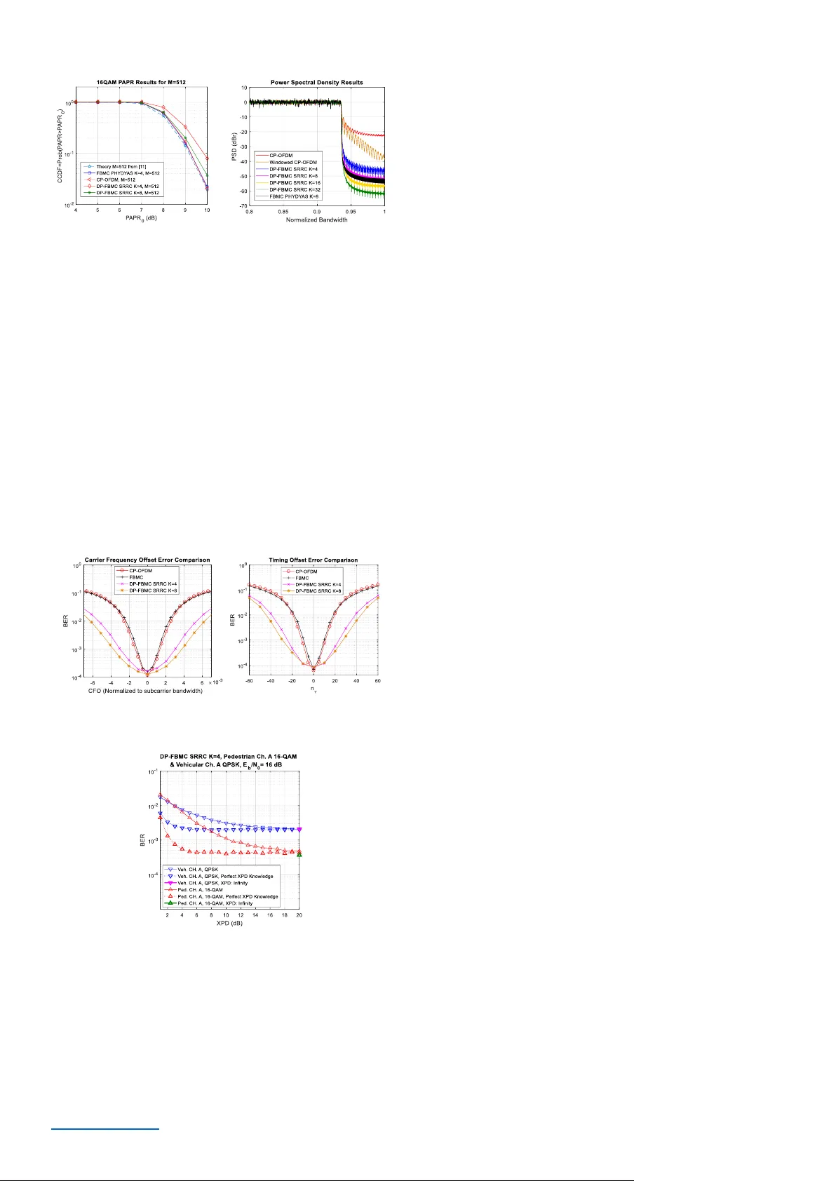
This paper is accepted to be published in I EEE Vehicular Tech nology Conference ( VTC ) FALL 2018. arXiv:1806.05143 Dual-Polarization OFDM-OQAM Wireless Communication System Hosseinali Jam al, David W. Matolak Departm ent of Electrical Eng ineering University of Sou th Carolina Columbia, SC, USA hjamal@email.sc.edu, matolak@cec.sc.edu Abstract — In this pap er we d escribe the overa ll idea and results of a recently proposed radio access technique based on filter bank multicarrier (FBMC) comm unication syste m using two orthogonal polarizations: dual- polarization FBMC ( DP -FBMC). Using this system w e can alleviate the intrinsic interference problem in FBMC system s . This enables use of all the multicarrier techniques used in cy clic-prefix orthogonal frequency-division multiplexing ( CP -OFDM) systems for channe l equalization, multiple-input/multiple-output (MIMO) processing, etc., without using the ex tra process ing re quired f or conventional FBMC. DP- FBMC a lso provides o ther interesting advantages o ver CP-OFD M and FBMC su ch a s more robustness in multipath fading channels, and more robustness to receiver carrier frequency offset (CFO) and timing offset (TO). For DP -FBM C we pro pose three different structures based on different multiplexing techniques in ti me, frequency, and polarization . W e w ill show th at one of these structures has exactly the same system complexity and equipment as conven tional FBM C. In ou r simulation results DP -FBMC has better bit error ratio (BER) performance in d ispersive channels. Based on th ese results, DP -FB MC has potential as a promising candidate for future wireless commun ication systems. Keywords — DP -FBMC-OFDM-MIMO- CFO -XPD I. I NTRODUCTI ON OFDM with cyclic p refix (CP) is the most wides pread multicarr ier commun ication sy stem due to i ts simplicity and robustness against frequency selective channels. But it loses spectral efficiency in highly -dispersiv e channels w here a la rge portion of each O FDM sy mbol should be ad ded as CP. Also, t he OFDM pow er spect rum is not compact due to the si n(x)/x (sinc) frequency respons e of i ts re ctangular pulses, therefore it re quires window ing techniques and a large number of gu ard subc arriers to reduce the out- of -band (OOB) power emission . As an alternativ e, FBMC has been propose d to increase the spectra l efficiency via a more compac t power spectr al density (PSD) [1] , [2]. FBMC ’s n on-rectangu lar pulse shapes do not require a CP and therefore FBMC c an achieve larger spectrum efficiency, and lower OOB power. In this paper w e investigate the widespre ad FBMC techni que based on Saltz berg’s m ethod [ 3]. In recent years this system has seen m uch interest. T his communication system is also know n as stagg ered multit one (SMT) F BMC or OFDM-offs et quadratur e am plitude modulation (OQAM) [1]. T his techniqu e enables sy mbol-rate spacin g between adjacent subcarri ers without inter-sym bol inte rference (ISI) an d int er-carrier interfer ence ( ICI ) in dist ortionless channels . This works by a shift of half the sy mbol perio d betw een in-phase and qu adrature components of QAM sym bols [3]. In F BMC, because of th e real nature of the symbols, the orthogonali ty condition is only satisfied in the real d omain, and in dispersive channels where the channel respons e is in genera l com plex, FBMC suffers from imagin ary in trinsi c interference . In order to mitigate this interfer ence we require an int erference cancellation metho d . In the literatur e we find several methods for mitig ating this interfer ence, but almost all of these t echniques add com plexity [4]-[6 ]. Using polariz ati on -divis ion multiplexing (PDM) we can multiplex signals o n electr omagnetic waves of tw o orthogon al polarizati ons on the s ame carrier f requency with out any interfer ence, assum ing perfect (infinite ) cross-pola rization discrim ination ( XPD). T he XPD is the ratio of the signal amplitudes on the desi red polarizat ion to th at on the opposite polarizati on. In [7] this tech nique has been reported in satellite television links to double the throughput. It has also been studied for fibe r optic communication link s us ing tw o orthogonal left- and right-hand circu larly polarize d ligh t be ams in the sam e lig ht guide fiber at the same frequency [8]. Using PDM in terrest rial and veh icular wireless communication envir onments to double the capacity is ne arly impossible when platforms are mobile, due to the non-stabil ity of antenna positi on and often rich scattering in the w ireless chan nels. In th is paper w e use the PDM tech nique and pr opose dual- polarizati on FBMC (DP-FBMC) not to double the capacity but instead to solve the intrinsic im aginary interference proble m of FBMC systems: by usin g two polarizati ons we add an extra dimension to su ppress the intr insic in terferenc e. We will show that DP-FBMC has the advantage of significan tly suppressin g this interfer ence thanks to the polarization mu ltiplexing and the use of pr oper proto type filte rs . Th is pa per is organize d as f ollows: in Secti on II we des cribe the conventional OFDM-OQ AM system model. I n Section III we describe the proposed DP-FBMC commu nication sys tem , and in Section IV we provide simulation results for bit error ratio (BER) perform ance comparin g CP -OFDM, FBMC, and DP - FBMC in ITU pedest rian A and veh icular A channel m odels . We also compare the p eak- to -averag e power ratio (PAPR) and PSD of these system s, and evaluate DP -FBMC perfo rmance versus car rier frequen cy and tim ing offs ets, as well as BER perform ance in low XPD conditions . In Secti on V we pr ovide conclusions and brief ly desc ribe future w ork. This paper is accepted to be published in I EEE Vehicular Tech nology Conference ( VTC ) FALL 2018. arXiv:1806.05143 II. C ONVENTIONAL OFDM -OQAM In OFDM-OQAM, real valued OQA M symbols at subcarrier index n and symbol index m , are f iltered and modulated o n different subcarriers , as described b y th e following equation, where h ( t ) is the p rototype filter w ith length KT , and K is termed the o verlapping factor. T he exponential par t in this equa tion modulates the filtered OQAM symbols on to M subcarriers with 1/ T 0 frequency spacing, along with an extra phase component to ad d the π /2 p hase s hifts to adjacent symbols in order to satisfy the real orthogonalit y condition [2]. Based on this structure, OFDM-OQAM symbols are offset or overlapped by T 0 /2 in ti me to y ield maximum sp ectral ef ficiency. Relative to CP-OFDM, o ne m ain shortco ming of OFD M-OQ AM is its complexity. In order to r educe thi s co mplexity w e can use polyphase network (PPN) structure s at both trans mitter a nd receiver and use fast and inverse fast Fourier tr ansform s [2 ] as shown in Figure 1 . For details regarding PPN structures and I FFT/FFT based OFDM-OQAM imple mentations refer to [2] , [ 10]. In the FBMC tr ansmitter, after the IFFT block, subcarriers will be filtered throu gh the PPN network. Fo r each block of M i nput subcarriers, the par allel to serial (P /S) o utput sequence is a signal vector w ith the same length as the prototype f ilter. T hese signal s equences are the n ov erlapped at T 0 /2 intervals. T he reverse process is followed at the receiver. In order to illustrate the transmitting OQ AM symbols in time and freque ncy we use the ti me-frequency phase -offset diagram. In Figure 2 we sho w this diagram for OFDM-OQ AM. In this structure the solid circles and s quares denote the π /2 phase shifts between adjacent symbols (ad jacent i n both ti me and frequency d omains). In the following equations we anal yze the intri nsic imaginary interference in FBMC . First we re-write (1) as follows, where, In (3), rep resents the time shift ed and freque ncy modulated versions o f the pro totype filter response h ( t ). Here the real ortho gonality conditio n o f OFDM - OQ AM system c an be expressed as, where is the Kronecker delta functio n, equal to o ne if n = p and 0 i f n ≠ p , a nd is the real part of the quantity i nside the braces, and k is an y i nteger. I n disper sive multipath channe ls we can write the received symbols as follows, where are the complex channel transfer function sa m ple s at subcarr ier n and symbol m, is the so called intrinsic interference, and is the additive w hite Gaussian noi se (AWGN) variable. As long as the values are com plex, the real valued trans mitt ed symbols w ill su ffer from the p resence of the intrinsic interference at the receiver. Therefore we need to fi nd a way to remove the . In [ 4 ] the authors proposed an interesting tec hnique to remove t his i nterference based on “ auxiliary pilot s.” In this paper we also use this technique for channel equa lization in the conventional FBMC system. To calculate we first defi ne t he following prototype filter time -frequency localization function, From (4) and (5) w e note that (6) are pure ly real val ues for n ≠ p or m ≠ q . Now we ca n calculate t he knowin g the adjacent rea l OQAM symbols fro m, where, (a) . . . . . . . . . Overlapping ( M /2 inte rval) D/A, ... Tx Ant enna (b) Figure 1. OQA M-OFDM communicat ion system; (a) trans mitter, (b) re ceiver. . . . . . . ..., A/ D . . . Rx Antenna Figure 2. FBMC sy mbols time-fre quency phase-space lattice ( M =16). t f ... ... ... ... This paper is accepted to be published in I EEE Vehicular Tech nology Conference ( VTC ) FALL 2018. arXiv:1806.05143 Now by definin g a reference symbol , is the set of nearby indices with frequency within subcarr iers and t ime within symbols of the reference subcar rier and symbol indices ( n =0, m =0). In practice , usin g well-localized protot ype filters, can be selected a s sm all as o ne [ 5]. This means that most of the intrins ic interference res ults from the adjacent symbols and interference from symbols outside t he neighborhood is negligible. Of course in our analysis as we describe in detail in [1 3], eq uations ( 5)-(8) rely on the assumption of channels with lo w frequency se lectivity, rel ying in a flat fading mod el for the subchannels. III. P ROPOSED DP -FBMC S YSTEM In this section we describ e the proposed DP-FBMC communication system fro m [ 13]. In this DP -FBMC proposal we define three different DP -FBMC multiplexin g structures. In Figure 4 diagrams we show the time-frequency-polarizat ion phase-lattice structure of all DP -FBMC str uctures. Structure I is Based on time-polarization division multiplex ing (TP DM) . In this method we isolate adjacent symbols on two or thogonal polarizations by time multiplexing of ad jacent OQ AM sy mbols . This approach removes the intrinsic interference t hat resu lts from ad jacent symbols (assuming perfect cross -polarization), bu t some of t his interference still exist s on adjac ent subcarriers during each symbol per iod. In S tructure II w e use a frequency-division multiplexing technique (FPDM) as shown in Figure 3( b). In this approach we isolate the adj acent tr ansmitt ed subcarriers on the t wo polarizations by frequency multiplexing of symbols. Figure 3(c) shows the DP-FBMC Stru cture III based o n time- frequency-polarizatio n division multiplexing (T FPDM). In this structure using bo th time and frequenc y multiplexing we separate half the subcarriers on both polarizations at every symbol period, and the order of subcarriers changes at subsequent symbol p eriods. To better understand the DP - FBMC idea, i n Tab les 1 to 3 we provide numerical exa mples of t he intrinsic interference values surrounding e very r eference s ymbol f or the filter s based on isotropic orthogon al transfor m al gorithm ( IOT A ) technique [ 15 ], P HYDYAS [9], and square-root raised cosine (SRRC) with overlappin g fac tor K = 4, resp ectively. In these tables w e colo red the symbol locations based on DP -FB MC Structure III . Here th e red samples represent the tim e-freque ncy filter response on the same po larization as the subject s ymbol, and the black symbols are o n t he o ther po larization with no interference to the s ubject symbol ( again as suming per fect polarization isolation). As we notice from t his table the interference caused fro m adjacent subcarriers is supp ressed entirely but t here are still symbols (red) on the sa me polarization that can cause in terference. For the SRRC filter, via so me numerical trials, we determined heuristically that a roll-off factor = 2/ K is a good choice and we chose alpha factor one f or IOTA . As can be see n, from Tables 1 to 3, the red intrinsic i nterference sample values decrea sed, and as will be shown, SRR C filters w ill yield better BER performance. T o obtain eve n lower intrinsic i nterference values with the SRRC, we can increase the overlapping factor at the co st of slightly increasing complexity and f rame length. In Figure 4 w e plot the normalized impulse respo nses of these filters. (a) t f ... ... ... ... Transmitte d Symbols on Vertica l Antenna Transmitte d Symbols on Horizontal Ante nna (b) t f ... ... ... ... Transmitte d Symbols on Vertica l Antenna Transmitted Symbols on Horizontal Antenna (c) Figure 3 . DP -F BMC structures, (a) Structur e I based on TPDM, (b) S tructure II based on F PDM, (c) Structure I II based on T FPDM . t f ... ... ... ... Transmitte d Symbols on Vertical Antenna Transmitte d Symbols on Horizontal Antenna Table 1 . I OTA values for p = [-2, 2 ], q = [ -3, 3] a nd K =4. p\q -3 -2 -1 0 1 2 3 -2 -0.0194j 0 0.0413j 0 -0.0413j 0 -0.0194j -1 0.0116j 0.0413j 0.2327j 0.4378j 0.2327j 0.0413j 0.0116j 0 0.0194j 0 0.4380j =1 -0.4380j 0 -0.0194j 1 0.0116j -0.0413j 0.2327j -0.4378j 0.2327j -0.0413j 0.0116j 2 0 0 0.0413j 0 -0.0413j 0 0 Table 2. PHYDY AS values for p = [-2, 2], q = [-3, 3] an d K = 4. p\q -3 -2 -1 0 1 2 3 -2 -0.0644j 0 0 0 0 0 -0.0644j -1 0.0442j 0.1250j 0.2058j 0.2393j 0.2058j 0.1250j 0.0442j 0 -0.0644j 0 0.5645j =1 -0.5645j 0 -0.0644j 1 0.0442j -0.1250j 0.2058j -0.2393j 0.2058j -0.1250j 0.0442j 2 0 0 0 0 0 0 0 Table 3. SRRC values for p = [-2, 2 ], q = [-3, 3] and K =4. p\q -3 -2 -1 0 1 2 3 -2 -0.1122j 0 0 0 0 0 -0.1122j -1 0.095j 0.1263j 0.15j 0.1589j 0.15j 0.1260j 0.095j 0 0.1122j 0 0.6015j -0.6015j 0 -0.1122j 1 0.095j -0.1263j 0.15j -0.1589j 0.15j -0.1260j 0.095j 2 0 0 0 0 0 0 0 This paper is accepted to be published in I EEE Vehicular Tech nology Conference ( VTC ) FALL 2018. arXiv:1806.05143 In [13] w e provide analysis of com plexity for all DP-FBMC structures. As a q uick comple xity review first we note t hat for DP -FBMC Structures II and III we need a second IFFT and FFT at both transmitter an d receiver, therefore they have h igher complexity than co nventional FBMC. For Structure I , as long as w e can share the same IFFT/FFT at every sym bol period and polarization we o btain the sa me co mplexity and eq uipment as conventional FBMC. In this paper w e focus o n Structure I in simulations a nd ana lysis; more results and a nalysis are pr ovided in [13]. For DP -FBMC syste m s, as lo ng as the channel equalization p rocess is being do ne separately on b oth polarizations, the eq ualization complexity is higher than for conventional FBM C, and as will be shown, this is the cost for better performance. IV. S IMULATIO N R ESULTS We compare the BER per formance o f CP-OFDM, conventional FBMC, and DP-FBMC via simulations. Note that in ou r simulation first we p rovide results assuming perfect XPD, and at the end results for so me realistic XPD values. In our simulations following t he ap proach in [ 13 ] we evaluate BER performance in t w o multipath fading channels. W e compare PAPR, and the e ffects of car rier time and freq uency offsets. We also sho w the P SD of DP-FBMC using different prototype filters and overlapping factors. T hese si mulations were p erformed at baseband with no c hannel coding. W e have M = 51 2 subcarriers with 16 symbols on each frame, a nd the signal band width B = 10 MHz . hence the temporal sy mbol interval is T 0 = 512/10 7 = 51.2 µs. As mentioned in [1 3], the mean RMS -DS values for p edestrian a nd vehicular A chann els are 4 6 and 370 ns, respec tively. For channel models w e chose pedestrian and vehicular channels A from IT U-R recommendation M.1225 [ 10 ]. In these simulation s we ass ume Rice an fading with Rice fact or 10 dB for the pedestrian and Rayleigh fading for the vehicular. For CP -OFDM we cho se M / 16 of a symbol period for the CP for both pedestria n channel A, and vehicular channel A. Fo r conventional FBMC we chose the P HYDYAS prototype filter with K = 4. We use 33 subcarriers for guard band (17 on the left and 16 on the right of the signal spectru m ), and also null the DC subcarr ier. For channel e stimation we use scattered -pilot sy mbols on 3 0 equally spac ed subcarriers with 4 symbols tempo ral spacing . For channel equalization, we used the least squares (LS) and discrete Fourier tr ansform (DFT ) -based channel esti m ati on noise red uction and spline interpo lation technique [ 12 ]. I n FBMC we used the a uxiliary pilot techn ique based on [ 4]. For all communication systems we assume perfect timing offset estimation and synchro nization. In Figures 5( a) and 5(b) we plot B ER vs. E b / N 0 for 16 -QAM and QPSK modulations in the pedestrian A and vehicular A channels, respectively. As explained in [ 13 ], S tructures I and III h ave sim ilar BER results, therefore w e only sho w the results using S tructure I . Accordin g to these results DP-FBM C has better B ER p erforman ce tha n CP -OFDM and conventional FBMC after channel equalization for highly d ispersive channels (Vehicular channel) . Here w e also plot BER results with perfect channel knowledge and ze ro-fo rcing technique. This better DP -FBMC BER is due to l ar ger temporal spacing of each of the po larization ’s symbols. In DP -FBMC Structures I and III b ecause of the time multiplexin g, o n both structures the symbol spacing increa ses co mpar ed to the symbol spaci ng in conventional FBMC. This yields lower ISI in multipa th channels and hence lo wer B ER. Also, as can be seen using the IOTA filter slightly w orse ns the BER. This is because using DP -FBMC S tructure I , the interferences ca used fro m adjac ent symbols and adj acent subcarriers are equal if the IOTA pulse shaping filters are u sed. Her e we note t hat IOTA filter has almost same result (results ar e not shown here) co mpar ed to other f ilters in DP-FBMC Structure III , because in Structure III the symbols are multiplexed both in time and frequency domains. We also note that as expected for higher overlapping factors, SRRC filter r esults better B ER results. Figure 6( a) pro vides PAPR complementary c umulative distribution function results f or these syste ms. For FBMC systems we assume frame structures without end tails caused from filter tails fro m the overlapping factor . In [ 14 ] we study the PAPR of DP -FBMC syste ms in detail. As ca n be seen, the DP -FBMC S tructure I has P APR very close to that of conventional FBMC a nd CP -OFDM for larger o verlapping factors suc h as K = 8. Here we al so note t hat DP -FBMC Structures II and I II have exactly the same PAPR as CP-OFDM and conventional FBMC with different o verlapping factors, because temporally all the sy m bol s are present the entire fr ame period. PSDs appear in Fig ure 6(b). N ote that in these results similar to P APR, we tr uncate two ends o f the frame waveforms due to filter tails in order to make the frame lengt hs as short as possible. We can observe that when DP -FBMC has the sa m e K as conventional FBMC, the PSD is nearl y identical. As expected, with SRRC as K incr eases, the OOB p ower decrea ses. Figure 4 . I OTA, PHYDYAS , and SRRC prototype fil ters impulse response s with K = 4. (a) (b) Figure 5 . BER vs. E b /N 0 , (a) 16 -QAM , I TU-R pedestrian A channel, (b) QPSK , ITU-R vehicular A channe l This paper is accepted to be published in I EEE Vehicular Tech nology Conference ( VTC ) FALL 2018. arXiv:1806.05143 Figures 7(a) and 7(b) plot simulated BER versus carrier frequency ( CFO ) and timing offset ( ) at the rec eiver, respectively, in an AWGN channel, with 16-QAM modulatio n, SNR = 1 2 dB and M = 512 subcarriers. The CFO values are normalized to the s ubcarrier bandwidth and n τ is the n umber of samples o ffset. Channel bandwidth B = 10 MHz. These results confirm that DP-FB MC has better performance in the presence of ti me a nd frequency offsets (and again, larger overlap ping factors slightly enhance the pe rformance). In Figure 8 assuming or thogonal circular p olarizations, we plot the 16 -QAM BER p erformance vs. XPD f ro m 1 to 20 dB in the pedestrian and vehicular chan nels with E b / N 0 = 16 dB . A s can be seen, smaller XPD degrades performance. In this Figure we also plot the BER perfor mance assuming perfect XP D knowledge at r eceiver ( after cr oss polarizatio n interferen ce cancellation). Thus in order to enhance the performance in very low XPD conditions, m ethods to esti mate and remove t he cross - polarization interference could b e investigated. V. C ONCLU S IO N In this p aper we proposed a no vel FBMC system based on a dual polar ization multiplexi ng technique . U sing dif ferent ti me, frequency, and p olarization multiplex ing schemes a nd SRRC filters we showed that we can significantly suppress the FB MC intrinsic imaginary interferen ce. In goo d XPD situations DP - FBMC shows significant advantages compar ed to conv entio nal FBMC and CD -OFDM in multipath fading cha nnels. DP - FBMC suffers when XPD is very small, therefore in future work XP D esti mation and c ancellation techniques co uld be investigated using pilo t symbols. R EFERENCES [1] B. Farhang- Boro ujeny, “OFDM Versus Filter Bank Multicarrier,” IEEE Signal Processin g Magazine , vol. 28, no. 3, pp. 92-112, May 2 011. [2] P. Siohan, C. Siclet and N. Lacaille, “Analysis and d esig n of OFDM/OQA M systems based on filterbank theory ,” IEEE Trans. Si gnal Processing , vol. 50, no. 5, pp. 1170-1183, M ay 2002. [3] B. Saltzberg, “Perf ormance of an Efficient Paralle l Data Transmission Syste m,” IEEE Tran. Comm unication Tec hnolo gy , vol. 15, no. 6, pp. 805- 811, Decembe r 1967. [4] J. P. Java udin, D. L acroix and A. Rouxel , “Pilot -aided c hannel estimation for OFDM/OQAM,” IEEE Spring Vehicular Tech. Conf (VT C), pp. 1581- 1585 , Jeju, So uth Korea, South K orea ), 22 -25 April 200 3. [5] R. Nisse l and M. Rupp, “Enabli ng Low -Complexity MI MO in F BMC- OQA M,” IEEE Globecom Workshops (GC Wkshps) , Washington, DC , pp. 1-6, 2016. [6] J. W ang, H. Zhao, Y. Zhang, F. Li and L . Zhao, “I ntrinsic I nterference Elimination for Preamble- Based Channe l Estimatio n in FBMC Syste ms,” IEEE Glo becom Works hops (GC Wkshps) , W ashington, DC, 2016, p p. 1- 5. [7] I nternational Te lecommunications Union (ITU), Report ITU -R M.2175 , “Simultaneo us dual linear polarization transmission technique using digital cross- polariz ation cancel lation for MSS sy stems”, July 2010 . [8] F . Horlin, J. Fickers, P. Emplit, A.Bo urdoux, and J. Louve aux, “Dual - polarization OFD M-OQAM for communications over optical fibers with coherent detec tion,” Optics Express 21 , pp. 6409-6421, 20 13. [9] M. Bel langer, et al . “FBMC p hysical laye r: a primer.” PHYDYA S, no. 4, Jan 2010. [O nline]. Available : http://www .i ct- phydyas.or g/teamspace/internal-folde r/FBMC-Primer_06-201 0.pdf [10] International Te lecommunications U nion (ITU) , R eport ITU -R M .1225, “Guidelines for e valuation of radio t ransmission technol ogies for IMT - 2000, ” 1997. [11] T. Jiang, M. Guizani, H. H. Chen, W. Xiang and Y. Wu, “Derivation of PAPR Dist ributio n f or OFDM Wireless Syste ms Based on Extre me Value Theory ,” IEEE Tran. Wireless Comm. , v ol. 7, no. 4 , pp. 1298-1305, April 2008. [12] Y. S. Cho, J. K im, W. Y. Yang, and C . G. Kang, MIMO- OF DM Wireless Communications with MATLAB . Singapore: John Wiley & Sons (Asia) Pte Ltd, 2010. [13] H. Jamal, D. W. Matolak, “Dual -Pol arization FBMC for I mproved Performance in Wireless Communic ation Systems”, submi tted t o IEEE Tran s. on Vehicular Technolo gy , May 2018. [14] H. Jamal, D. W. Matolak, “PAPR A nalysis for Dual - Polarization FBMC”, submitted to IEEE MIL COM Confere nce , May 2018. [15] B. L e Floch, M. Alard, and C. Berrou, “Co ded orthogonal frequency division multiple x,” Pro ceedings of the IEEE , vol. 83, n o. 6 , p p. 982 – 996, June 1995. Figure 6 . (a) CCDF vs. PAPR 0 , (b) PSD vs. normalized bandwid th (a) (b) Figure 7 . (a) BER vs. CFO, (b) BER v s. TO , AWG N channel, E b / N 0 =12 dB, 16 -QA M, M =512. Figure 8 . . BE R vs. XPD, DP -FBMC Str ucture I , SRRC Fil ter with K =4, 16 - QAM, ITU -R pedestrian and vehicula r A channels , E b /N 0 =16 dB.
Original Paper
Loading high-quality paper...
Comments & Academic Discussion
Loading comments...
Leave a Comment