String Diagrams for Assembly Planning
Assembly planning is a difficult problem for companies. Many disciplines such as design, planning, scheduling, and manufacturing execution need to be carefully engineered and coordinated to create successful product assembly plans. Recent research in…
Authors: Jade Master, Evan Patterson, Shahin Yousfi
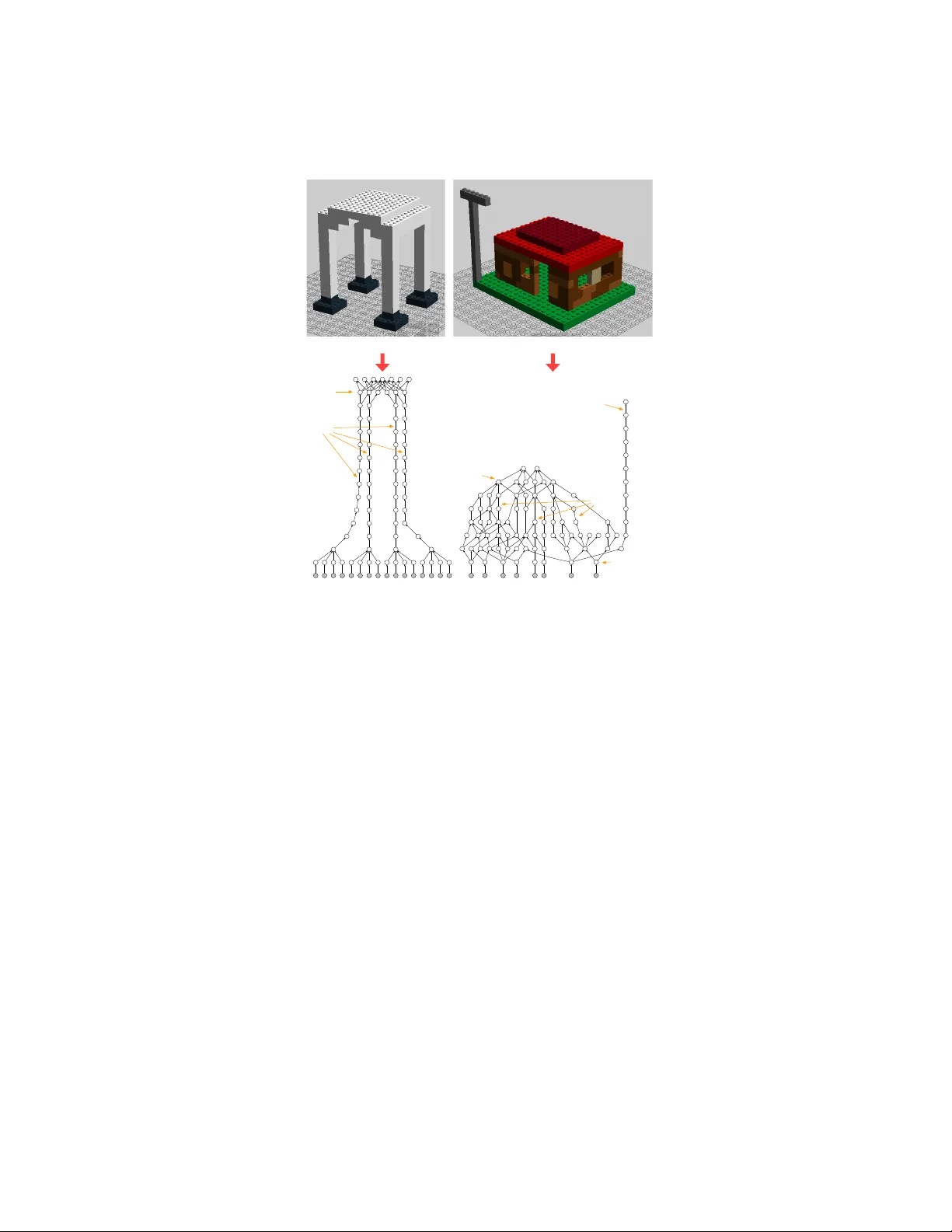
String Diagrams for Assem bly Planning ? Jade Master 1 [0000 − 0003 − 1970 − 6030] , Ev an P atterson 2 [0000 − 0002 − 8600 − 949 X ] , Shahin Y ousfi 3 , and Arquimedes Canedo 3 [0000 − 0003 − 3506 − 6563] 1 Univ ersity of California Riverside, Riv erside CA 92507, jmast003@ucr.edu 2 Stanford Universit y , 450 Serra Mall, Stanford, CA 94305, evan@epatters.org 3 Siemens Corp orate T ec hnology , 755 College Rd E, Princeton, NJ 08540 arquimedes.canedo@siemens.com Abstract. Assem bly planning is a difficult problem for companies. Many disciplines such as design, planning, sc heduling, and manufacturing ex- ecution need to b e carefully engineered and co ordinated to create suc- cessful pro duct assembly plans. Recen t researc h in the field of design for assembly has prop osed new methodologies to design product structures in such a wa y that their assembly is easier. How ever, presen t assembly planning approaches lack the engineering tool support to capture all the constrain ts associated to assembly planning in a unified manner. This pa- p er proposes CompositionalPlanning , a string diagram based frame- w ork for assem bly planning. In the proposed framework, string diagrams and their comp ositional properties serve as the foundation for an engi- neering to ol where CAD designs interact with planning and scheduling algorithms to automatically create high-qualit y assem bly plans. These assem bly plans are then executed in simulation to measure their p er- formance and to visualize their key build characteristics. W e demon- strate the versatilit y of this approach in the LEGO assem bly domain. W e developed tw o reference LEGO CAD mo dels that are pro cessed by CompositionalPlanning ’s algorithmic pipeline. W e compare sequen- tial and parallel assem bly plans in a Minecraft simulation and show that the time-to-build p erformance can b e optimized b y our algorithms. Keyw ords: String Diagrams · Assem bly Planning · Category Theory 1 In tro duction T o da y , mass customization of pro ducts such as automobiles and consumer elec- tronics is forcing companies to provide a very large pro duct v ariety to address the diverse customer requirements. Digital man ufacturing technologies mak e it p ossible to accommo date mass customization during pro duct design and man- ufacturing. F or example, parametric designs in computer aided design (CAD) soft ware allo w for the sp ecification of configurable pro ducts, and computer aided man ufacturing (CAM) algorithms allow for the fabrication of pro ducts on differ- en t mac hines. Unfortunately , there is very limited engineering to ol supp ort for ? All authors contributed equally to this work while at Siemens 2 J. Master, E. Patterson et al. pro duct assembly planning. Although some companies use design for assembly (DfA) [19] and design for manufacturing and assembly (DfMA) [13] metho dolo- gies that attempt to develop pro duct structures that facilitate their assem bly , their implementation is ad-ho c. Therefore, assem bly planning is a task that is lo osely coupled to the rest of the digital manufacturing pip eline. The ob jective of this pap er is to op en new a ven ues for inter op er able assembly planning that is tigh tly coupled to the upstream design activities, and the downstream assembly tasks. String diagrams are a p o werful graphical calculus for reasoning in category theory [27]. String diagrams hav e also prov en useful in many other domains. They hav e b een sho wn to provide a mathematically sound graphical language in domains including linguistics [9], systems engineering [6], and computer science [20]. Generally , string diagrams represent pro cesses which require and pro duce resources. Assembly planning is the discipline of understanding how to opti- mally chain assembly pro cesses together to craft a whole pro duct from separate parts [15]. Thus, string diagrams are a natural to ol for form ulating assembly planning problems and constructing their solutions. T o demonstrate this thesis w e show that string diagrams can b e used to build construction sc hedules for v arious LEGO models. F rom each LEGO 3D CAD file w e generate a c onne ctivity gr aph where the no des represen t LEGO pieces and the edges indicate that they are connected in the final mo del. Given a hierarchical clustering of this connectivity graph, we generate a c onstruction plan represented b y string diagrams whic h is hierarc hical, compositional, and interpretable. Using the formalism of string diagrams, complex sub-assemblies can be black b oxe d into larger string diagrams. Ha ving this hierarchical structure allows us to manipulate or adapt our plan at a desired level of abstraction. F urthermore, there is a categorical formalism that enables schedules to b e generated from these string diagrams. W e use top ological sorting, Girv an-Newman, and Leiden algorithms to generate assembly plans and schedules with different prop erties. Finally , we use Minecraft [3] as a simulator to v alidate the resulting sc hedules and measure their time-to-build p erformance. In this pap er, we demonstrate the versatilit y of this approach with a frame- w ork, CompositionalPlanning , that pro vides a new wa y of talking ab out as- sem bly planning. Our category theoretic interpretation pro vides a flexible math- ematical foundation that allows for an end-to-end demonstration from CAD design to assembly sim ulation. The contributions of this pap er are the follo wing: – w e sho w ho w string diagrams are an in tuitive yet mathematically sound language to represen t an assembly planning domain. – as large string diagrams can be tedious and cumbersome for humans to w ork with, our framework automates the creation of large string diagrams and thus eliminates the o verhead traditionally asso ciated with them. – a nov el algorithm that conv erts string diagrams to expr essions that result in highly parallel assem bly plans – a Minecraft based simulation en vironmen t mo dification or “mo d” to execute LEGO assem bly plans. String Diagrams for Assembly Planning 3 – w e publish the CompositonalPlanning framew ork as a Julia [4] pac k age for others to repro duce and build up on our work 4 . 2 Related W ork Assem bly planning problems and approaches ha ve been widely inv estigated. A comprehensiv e survey of them can b e found in [15]. In [30], a survey of as- sem bly design and planning systems is presented. In particular, the Assembly Se quenc e Planning (ASP) problem that w e target in this pap er is an NP-hard problem. ASP’s goal is to find a collision-free sequence of assembly op erations that put together individual parts given the geometry of the final pro duct and the relative positions of parts in the final pro duct. ASP is considered a combina- torial problem and therefore represen tations of the space of p ossible sequences has b een an active area of research [17]. While v arious represen tations ranging from AND-OR graphs [11] to Petri nets [24] hav e b een prop osed, w e are the first to study ASP under a category theoretic framework. In this pap er, w e show that category theory provides both an explicit and an implicit representation on assem bly sequences. On the one hand, string diagrams provide an explicit ASP represen tation of partial and full assem blies. On the other hand, expressions pro- vide us mathematical soundness and rigor as they implicitly enco de precedence assem bly relationships. Although this pap er fo cuses on LEGO and Minecraft mo dels, the Compo- sitionalPlanning framework can b e easily adapted to other domains. In 3D CAD mo deling, for example, parts are comp osed into assemblies in a similar w ay to how LEGO pieces comp ose into LEGO mo dels. The sp ecification of the parts themselves and their comp osition of assem blies is defined in a CAD file that is analogous to a LEGO 3D CAD file. Therefore, the first step would b e to create a custom parser for a sp ecific CAD file format to extract a connectivity graph from the information ab out parts and their comp osition. Giv en that there are many CAD file formats in the market to da y [8], the scalability of Com- positionalPlanning in the CAD domain is dep enden t on the av ailability of custom parsers. Related work in automated assem bly planning illustrates ho w this field is highly fragmented. Most researchers develop custom assembly planning solu- tions that work for sp ecific pro ducts and pro cesses. In [21], the authors present a system to address the assembly planning of multi-v ariant pro ducts in mo du- lar pro duction systems. The pro duct requirements and their feasible assembly orders are mo deled in a directed graph referred to as the A ugmente d Assembly Priority Plan (AAPP). The AAPP enco des how tw o initial subassem blies are joined together to form a new subassembly through a v alue adding task such as “assembly” or “screwing”. F rom the authors’ description, the AAPP can b e mapp ed as a string diagram to lev erage the planning capabilities of our Compo- sitionalPlanning framework. Similarly , the authors in [23] present a system 4 CompositionalPlanning - https://gith ub.com/Comp ositionalPlanning/ 4 J. Master, E. Patterson et al. to generate assembly pr e c e denc e gr aphs from CAD files. Similar to our results, they sho w that an assem bly precedence graph contains all the v alid sequences of an assembly . Their assembly precedence graphs correspond to our connectiv- it y graph, and their assembly sequences corresp ond to our plans and schedules. There are t wo imp ortan t differences compared to our work: (a) their means of user-in teraction and visualization are spreadsheets instead of graphs, and (b) their implemen tation is based on a proprietary CAD softw are. 3 Categorical Assem bly Planning F ramework Our CompositionalPlanning framework, shown in Figure 1, consists of fiv e reusable soft ware comp onen ts. The first step is to infer a connectivit y graph from the CAD mo del that describ es ho w the different parts come together in terms of their geometry (e.g., orientation) and assembly op erations (e.g., snap, glue, w eld, insert). This step is necessary b ecause most CAD mo dels list quantities of all parts and detailed structural functions in relation to a finished pro duct, and this information do es not directly map to their assembly . LEGO CAD Model Connectivity Graph Generation 6 4 5 1 2 3 7 Plan Generation Schedule Generation Minecraft Simulation Assembly Simulation f 6 4 g 5 i 1 2 j 3 h 7 k 9 6 4 5 8 1 2 3 7 f 6 4 g 5 i 1 2 j 3 h 7 k Sequential plan Parallel plan Execution Assembly Planning Design Fig. 1. CompositionalPlanning framework pipeline. The second step consists of plan generation [14] – describ ed by different string diagrams – that hav e differen t prop erties of order and parallelism. These plans, although expressed by different expressions of string diagrams, generate the same LEGO mo del as they: (i) bring an initial world to a goal world using a set of assem bly op erators, and (ii) minimally impose ordering constrain ts. The third step generates a schedule using a plan and a detailed knowledge of the execution environmen t (e.g., num b er of w orkers, machines). The job of the schedule generation [14] is to imp ose further ordering constraints on the assem bly op erator application to achiev e a robust (e.g., against failures) and time-efficien t execution of the assembly task (e.g., time-to-assembly). The fourth and final step consists of executing the schedule in a simulator to visualize the assembly task, and to generate p erformance metrics. Although this pap er fo cuses on LEGO CAD mo dels as an input, and Minecraft simulations as an output, our comp onen ts are domain agnostic, and they can b e easily adapted for use in other domains. String Diagrams for Assembly Planning 5 3.1 Connectivit y Diagram Generation from CAD CompositionalPlanning parses the text-based LDra w files [2] and automati- cally builds the connectivity diagram. Every LEGO mo del has a unique connec- tivit y diagram that describ es ho w the pieces are connected to eac h other. LDraw files [2] describ e all the bric ks in the mo del b y t ype (e.g., 2 × 2, 2 × 4), color, cen ter co ordinates ( x , y , z ), and a 3 × 3 rotation matrix. This LDra w file represents the bill of materials (BOM) of the LEGO model and do es not con tain an y informa- tion ab out the connectivity of the bric ks. Therefore, the first step is to parse this information from the LDraw file f and generate a list of LegoOb jects. The second step is to create a directed graph and add a no de for every ob ject in the LegoOb jects list. Note that these no des are not yet connected by edges. V ertical stacking is the most common op eration with LEGO bricks as shown in the example in Figure 1. Therefore, the third step in our framew ork is to infer the vertical connectivity in the LEGO CAD mo del. In LDraw’s co ordi- nate system − y is “up”. Therefore, tw o bricks are connected if: (a) the top face of one brick has the same y co ordinate as the other brick’s down face ( a.top y coord () == b.bottom y coord ()); (b) and their b oxes (defined by ( x, z ) cen ter co ordinates and the brick’s w idth and l eng th ) intersect (( abs ( a.x − b.x ) ∗ 2 < ( a.l ength + b.leng th )) and ( abs ( a.z − b.z ) ∗ 2 < ( a.w idth + b.w idth ))). F or ev ery connected pair of ob jects we create an edge from a to b in the connec- tivit y diagram. Other less common op erations such as horizontal stacking, and op erations inv olving other LEGO pieces such as p egs are left for future w ork. Ho wev er, the connectivity inference would follo w a similar principle as the one describ ed ab o ve. The fourth step consists of grounding all no des in the connectivity diagram that do not hav e any predecessors. Ha ving explicit ground no des helps the pro- cessing of the connectivity diagram by the following algorithms. As an illustra- tiv e example consider the LEGO mo del and its connectivity diagram sho wn in Figure 1. It consists of seven bricks sequen tially num b ered from 1 , ..., 7 . In addition, our algorithm also includes the “ground” no des to facilitate the mo del construction using the base build plate. In this example, the ground no des 9 and 8 connected to 6 and 1 , resp ectiv ely . Extending our framew ork b ey ond LEGO would require new parsers to read CAD file formats, and new inference algorithms to derive the connectivity b e- t ween parts. 3.2 String Diagrams String diagrams are diagrams where resources are represented by strings (wires) and pro cesses are represented by b o xes. F or example a process which snaps a p eg into a hole is represented by snap L1 L2 base 6 J. Master, E. Patterson et al. String diagrams can b e comp osed in sequence snap L 1 L 2 L 3 snap base C indicating that the pro cesses must b e p erformed in sequence. String diagrams can also b e comp osed in parallel buildcolumn buildro of A 1 A 2 B 1 B 2 indicating that the order in whic h the tasks are p erformed do es not matter. String diagrams also hav e algebraic expressions called morphisms. F or example, the first example has a corresp onding algebraic expression given by snap : L1 ⊗ L2 → base Note that this expression is b oth functional and typed. This makes Composi- tionalPlanning an efficient and type-safe framew ork. In a similar wa y , the expressions which string diagrams represent can b e comp osed in sequence and parallel using the t wo op erations ( f : x → y , g : y → z ) 7→ f · g : x → z (1) ( f : x → y , f 0 : x 0 → y 0 ) 7→ f ⊗ f 0 : x ⊗ x 0 → y ⊗ y 0 (2) Rather complicated expressions can b e built using these op erations, e.g., see the string diagrams in Figure 4. A natural question to ask is when t wo expressions corresp ond to the same string diagram. The answer to this question is essen- tial to understanding how planning domain dep endencies represented in string diagrams can b e algebraically manipulated. It turns out that if the algebraic expressions satisfy the right set of axioms, then the w ay that a string diagram is drawn is indep enden t of the expression it generates. A structure of algebraic expressions satisfying these axioms is a w ell-known structure in category theory called a symmetric monoidal category . In [18] it is shown that string diagrams unam biguously represent morphisms in a given symmetric monoidal category . The follo wing theorem ensures the soundness of string diagrams in the LEGO assem bly domain. Theorem 1. L et G = ( E , V ) b e a simple gr aph whose no des V r epr esent pie c es of a LEGO mo del and whose e dges E indic ate a c onne ction in the c omplete d structur e. Then, ther e is a symmetric monoidal c ate gory wher e: – an obje ct is finite tensor pr o duct X 1 ⊗ X 2 . . . X n of subsets of V i.e. al l p ossible tensors of sub assemblies. String Diagrams for Assembly Planning 7 – A morphism f : X 1 ⊗ X 2 . . . ⊗ X n → Y 1 ⊗ Y 2 . . . Y n is a c onstruction plan which turns the sub assemblies X 1 ⊗ X 2 . . . ⊗ X n into the sub assemblies Y 1 ⊗ Y 2 . . . ⊗ Y n using only the joins al lowe d by the e dges of G . – The c omp osite g · f r epr esents the c onstruction plan wher e f and g ar e p er- forme d in se quenc e. – The tensor pr o duct g ⊗ f r epr esents the c onstruction plan wher e f and g ar e p erforme d in p ar al lel. Pr o of. Symmetric monoidal categories can be freely generated from the data of a P etri net. In “On the Category of Petri Net Computations”, Sassone show ed that for a P etri net P , there is a strict symmetric monoidal category Q [ P ] whose ob jects are finite strings of places in your Petri net and whose morphisms cor- resp ond to str ongly c onc atenable pr o c esses [26]. These are sequences of even ts whic h can o ccur using the transitions of y our Petri net in sequence and in par- allel. Recall that a P etri net is a tuple ( T , P , s, t ) where – T is a finite set of ev ents which can occur, – P is a finite set of a v ailable resources, – s : T → P ⊕ is a function from even ts to multisets of resources indicating whic h resources are required for each even t and, – t : T → P ⊕ is a function from ev ents to m ultisets of resources indicating whic h resources are pro duced b y each even t. T o construct the desired symmetric monoidal category , we set T equal to P ( E ), the set of sub ets of edges in G and set P equal to P ( V ) the set of subsets of no des in G i.e. all p ossible sub-assemblies of the LEGO mo del. Define s : P ( E ) → P ( V ) ⊕ b y the rule { ( x 1 , y 1 ) , ( x 2 , y 2 ) , . . . ( x n , y n ) } 7→ { x 1 , x 2 , . . . , x n } + { y 1 , y 2 , . . . , y n } . where + indicates the o ccurrence of b oth subsets in the m ultiset P ( V ) ⊕ . Define t : P ( E ) → P ( V ) ⊕ b y the rule { ( x 1 , y 1 ) , ( x 2 , y 2 ) , . . . ( x n , y n ) } 7→ { x 1 , x 2 , . . . , x n } ∪ { y 1 , y 2 , . . . , y n } . The symmetric monoidal category in the theorem statemen t is obtained by tak- ing the category of strongly concatenable pro cesses on this Petri net. The next section describes how the string diagrams of these symmetric monoidal categories can b e leveraged to pro duce construction plans. 3.3 Planning A LEGO CAD mo del and its connectivity graph describ e an ob ject in its final, assem bled state, but not how to assemble it. A plan consists of step-b y-step instructions on how to assemble the atomic parts (LEGO bricks) in to the desired 8 J. Master, E. Patterson et al. ob ject. In general, there are many possible plans for assembling the same ob ject, corresp onding to different wa ys of forming intermediate sub-assemblies. F or us, plans are string diagrams. In suc h a diagram, the strings repre- sen t sub-assem blies and the b oxes represent op erations of joining together sub- assem blies to mak e a larger sub-assembly . F ormally , a sub-assem bly is a subset of the atomic parts, interpreted as b eing as sem bled. Each join op eration takes t wo disjoin t sub-assemblies A and B as inputs and pro duces a single output, the union A ∪ B . A plan is a string diagram that tak es all the singleton sets (sub-assem blies consisting of a single part) as inputs and pro duces as output the set of all parts (full assembly). Although every plan is v alid at this level of description, not ev ery plan will b e ph ysically feasible. As pro of of concept, we implemented t wo simple algorithms for assembly planning. In the se quential algorithm , we top ologically order the edges of the connectivit y graph. That is, we first top ologically order the nodes, where a top o- logical ordering is any total ordering consistent with the directed edges. Then w e lexicographically order the edges, viewed as ordered pairs of nodes. F or eac h edge, taken in this order, we join the tw o sub-assem blies containing the source and target, if they are distinct; otherwise, we do nothing. W e con tinue in this w ay un til all the edges hav e b een exhausted, at which p oin t the ob ject is fully assem bled. When the connectivit y graph is a path graph, the sequential plan is the ob vious plan that joins the parts together one-at-a-time. In the p ar al lel algorithm , we create more opportunities for parallelism by par- titioning the connectivity graph into comp onen ts, making plans on eac h comp o- nen t, and then treating these plans as black b o xes in a higher-lev el plan. This meta-algorithm has sev eral knobs to tune, and it can b e applied recursively . T o partition the graph, we can apply any comm unit y detection algorithm that finds non-o verlapping communities. In our exp erimen ts, we use the Girv an-Newman algorithm [16] and a v arian t of the Louv ain method [7], the Leiden algorithm [28]. W e p erform only one level of partitioning and we do sequen tial planning within eac h partition and also to assemble the resulting sub-plans. The use of comm u- nit y detection to find opp ortunities for parallelism is a heuristic, but works well in our exp erimen ts. 3.4 Sc heduling A plan, in the form of a string diagram, says what steps to p erform and ho w the steps dep end on each other. A sche dule extends the information in a plan by assigning the steps a definite order; formally , a schedule is any linear extension of the top ological ordering of the op erations (b o xes) in the plan. F or simplicit y , w e take a resource-agnostic view of sc heduling, in which the num b er of work ers is unkno wn at the time of planning and scheduling. The aim in scheduling is therefore to maximize the opp ortunities for parallelism, given the constraints imp osed by the plan [25]. Our scheduling algorithms ha ve t wo ma jor phases. First, w e create a syntactic expression represen ting the plan. In general, a single string diagram can b e String Diagrams for Assembly Planning 9 represen ted by man y differen t expressions; we construct one of them. W e then linearize the expression, using a simple recursiv e algorithm, to obtain a schedule. A small example will illustrate the relationship b et ween string diagrams and syn tactic expressions. Consider the string diagram shown in Figure 2, the com- p osite of f and g in parallel with comp osite of h and k . W e can represen t this diagram by either of the expressions ( f · g ) ⊗ ( h · k ) (read “ f then g , and h then k ”) and ( f ⊗ h ) · ( g ⊗ k ) (read “ f and h , then g and k ”). f g h k f g h k b) Expression 1 c) Expression 2 f g h k a) String diagram Fig. 2. Relationship b et w een string diagrams and syntactic expressions W e ha ve dev elop ed an algorithm to find an expression for an y string diagram represen ting a morphism in a symmetric monoidal category . As the algorithm is fairly elab orate, w e will not digress to present it carefully , except to say that it is inspired by existing algorithms that recognize in a DA G, or reduce a DA G to, a series-parallel digraph [29,22]. The second phase of scheduling is more straightforw ard. Ha ving formed an expression for the plan, w e sc hedule the plan by recursively linearizing the ex- pression tree. Given a comp osition f · g , we simply concatenate the schedules for f and g . Giv en a pro duct f ⊗ g , we interle ave the schedules for f and g , meaning that we tak e the first elemen t of the f -schedule, then the first elemen t of the g -sc hedule, then the second elemen t of the f -sc hedule, and so on, until the b oth sc hedules ha ve been exhausted. F or example, b oth of the ab o v e expressions ( f · g ) ⊗ ( h · k ) and ( f ⊗ h ) · ( g ⊗ k ) yield the same schedule ( f , h, g , k ). Note that the ordering of the monoidal pro ducts affects the schedule, so that f ⊗ g yields a different schedule than g ⊗ f . This pro cedure can b e seen as a sp ecial case of an existing algorithm for optimally sc heduling series-parallel digraphs [10]. 3.5 Sim ulation Minecraft is an immensely popular 3D op en-w orld video game where pla yers can build their own structures [12]. The game world and most of its elemen ts are made of different kinds of blo c ks. These blo c ks can b e used to create structures of any complexity . This versatilit y makes Minecraft a go o d fit to represent the CAD model and to sim ulate their assembly pro cess. It has already pro v en to b e a w ell-suited sim ulation to ol in other robotics domains [5]. T o execute the schedule generated by our framework we extended Minecraft b y a new mo d. With this “mo d” w e can simulate the whole assembly process of the CAD mo del describ ed b y the sc hedule. The sim ulation not only provides us with a comprehensible visual representation of the pro cess, but also allows us to quantify execution time and w orker o ccupancy of differen t schedules. 10 J. Master, E. Patterson et al. Our op en source Minecraft “mo d” executes the assem bly op erations in the correct order as dictated by the generated schedule. The geometric CAD infor- mation is encoded in the connectivity diagram and it is parsed by our mo d. Eac h LEGO brick is represen ted b y a single or multiple Minecraft blo c ks. The schedule and the op erations specified in it determine which and ho w many bricks can b e connected to eac h other p er step. In addition to the precedence constraints en- co ded in the sc hedule, w e can define a n umber of workers . Each work er is allo w ed to perform a single op eration per step. Op erations are dispatched to work ers in the order they app ear in the sc hedule. Only op erations for which a work er is a v ailable can b e executed. Hence, the level of parallelism of the sc hedule and the n umber of work ers determine the time it takes to complete the assem bly . Disjoin t sub-assemblies are assembled in their own area resp ectiv ely un til they are connected to each other forming a new (sub-)assembly . The assem bly pro- cess is finished when all of the schedule’s operations hav e b een completed by the a v ailable work ers. 4 Results T o v alidate the CompositionalPlanning ’s pip eline w e designed the t wo LEGO CAD mo dels shown in Figure 3(a-b). The design ob jectiv e w as to hav e tw o LEGO mo dels of around 100 bricks each with a ric h set of features and a few h uman-intuitiv e sub-assemblies to v alidate our approach. The Columns mo del (Figure 3(a)) is inspired by roman temples and consists of 77 bricks. This mo del consists of four column sub-assemblies, each comp osed of 12 vertically stack ed 2 × 2 bric ks each. The ro of sub-assembly consists of tw o pairs of supp ort b eams, eac h arranged in a stair configuration supp orting a flat ro of. The House mo del (Figure 3(b)) consists of 86 bric ks. The house foundation sub-assembly consists of eight 4 × 10 green bricks and supp orts the house sub-assem bly and an electric p ole. The house sub-assembly consists of four non-identical walls. W e designed eac h wall using different comp ositions of bricks (i.e., 1 × 1, 1 × 8, 1 × 10, 1 × 2 × 2, etc.) that result in differen t connectivit y features as highlighted by the different shades of brown. The front wall has a square window and a do or. The tw o side w alls hav e tw o windows eac h while the back wall is solid. The four walls supp ort a t wo lay er ro of. The p ole sub-assembly consists of eleven 1 × 1 bric ks, and one 1 × 6 bric k on top. 4.1 Connectivit y Diagrams The generated connectivity diagrams for the tw o CAD mo dels are sho wn in Figure 3(c-d). The Columns mo del w as designed with regularity and symmetry in mind. These features are explicit in its connectivity diagram in Figure 3(c) with the four long strands representing the columns, and the dense lay er on top representing the ro of. On the other hand, the House mo del w as designed with asymmetry and irregularity in mind. These features are clearly visible in its connectivity diagram in Figure 3(d). In the House connectivit y diagram, the String Diagrams for Assembly Planning 11 a) Columns - 77 bricks b) House - 86 bricks 1 15 37 2 14 3 4 7 9 5 6 8 17 10 45 11 44 38 12 39 13 84 16 33 36 18 19 35 20 27 29 21 22 25 23 24 26 82 83 28 30 31 32 34 86 40 41 42 43 47 75 46 85 48 49 50 51 74 52 53 54 55 56 57 71 58 59 60 61 62 63 64 65 66 67 68 69 70 72 73 76 77 78 80 79 81 87 88 89 90 91 92 93 94 1 11 2 12 3 4 5 6 7 8 9 10 13 14 28 29 57 58 59 60 15 16 17 18 19 20 21 22 23 24 25 26 27 30 33 31 32 62 37 34 35 36 61 38 39 40 41 42 43 44 45 46 47 48 49 50 51 52 53 54 55 56 63 64 65 66 67 68 69 70 71 72 73 74 75 76 77 78 79 80 81 82 83 84 85 86 87 88 89 90 91 92 93 Columns Roof Pole Roof Foundation Walls c) Columns - connectivity diagram d) House - connectivity diagram Fig. 3. LEGO CAD mo dels and their inferred connectivity diagrams. w alls are irregular and asymmetric with gaps representing the windo ws and the do or. The p ole is represented b y the long strand. T ypically , LEGO mo dels come with assembly instructions, or build instruc- tions [1]. These instructions are, most likely , made for human enjoymen t and therefore must b e in tuitive. One natural wa y to organize these instructions is by sub-assem blies suc h that humans can relate to the structure they are construct- ing (e.g., a house). In some cases, these sub-assemblies are obvious. F or exam- ple, the column and ro of sub-assemblies in the Columns connectivity diagram (Fig. 3(c)) are easily distinguishable and therefore can b e decompose d into a reasonable build plan. How ever, there are other cases when these sub-assemblies are not obvious. F or example, decomp osing the in terlinked wall sub-assembly in the House mo del (Fig. 3(d)) into a reasonable plan is not trivial. F or b oth ex- amples, our plan generation pip eline on string diagrams can b e used to generate sequen tial and highly parallel assembly plans. 4.2 Plan Generation In this pap er, the qualit y of an assembly plan is determined in terms of how man y op erations can b e executed in parallel, rather than on maximizing human 12 J. Master, E. Patterson et al. enjo yment. F or eac h LEGO CAD model, w e generate t wo schedules. A sequen tial sc hedule is generated by top ologically sorting the connectivity diagram, and a parallel schedule is generated with the algorithms introduced in Section 3.3. Figure 4 shows the sequential sc hedules generated for the Columns and the House mo dels. The c olumn symmetry in the Columns mo del allows the sequential schedule to exp ose some parallelism as shown in Figure 4(a). If several work ers are av ail- able, this natural parallelism can b e exploited to reduce the time-to-build. The sequen tial schedule for the House mo del, as shown in Figure 4(b), exp oses very little parallelism due to the asymmetry and irregularity in the mo del. These tw o examples help us illustrate the inheren t limitations of sequential schedules. … b) House model sequential plan a) Columns model sequential plan Fig. 4. Sequen tial plans generated for the tw o LEGO CAD mo dels. Using the parallel plan generation algorithms describ ed in Section 3.3, our framew ork exp oses higher levels of parallelism as shown in Figure 5. Here, the blac k b o xes corresp onding to a partitioning of the connectivity diagram are sho wn b y the lab eled black b o xes. The num ber in each black b o x represents the n umber of bricks within the black b o x sub-plan. The execution sc hedules are deriv ed from these parallel plans. Even in the case of a purely sequential plan of the blac k b o xes (represen ted b y the width of the blac k b o xes), it can b e observ ed that the amount of parallelism is higher compared to the sequen tial schedules in Figure 4. In particular, the House mo del’s parallel plan in Figure 5(b) exp oses m uch higher parallelism when compared to the its sequential plan in Figure 4(b) consisting of a stairs configuration with minim um parallelism. 4.3 Sim ulated Schedu le Execution The sc hedule and the num b er of work ers determines how many op erations can b e executed in parallel. This parallelism can b e visualized in the sim ulation when multiple sub-assemblies are constructed at the same time. Figure 6 sho ws a time-lapse of the parallel assembly pro cess for the Columns and House mo dels String Diagrams for Assembly Planning 13 18 18 19 19 19 7 6 16 12 14 17 13 9 a) Columns model parallel plan b) House model parallel plan Fig. 5. Parallel plans generated for the t wo LEGO CAD mo dels. The width of the blac k boxes represent a sub-plan (i.e., a stairs configuration). with an unlimited n umber of w orkers. The top row sho ws the assembly pro cess at an early stage after a few blo c ks were already added. Note the parallel con- struction areas of the assem blies highlighted by the red squares. F urthermore, the main construction area where pieces and sub-assemblies will ev entually b e connected to each other can b e recognized. Sub-assemblies that are connected to the ground are not constructed in separate construction areas but at their final p osition in the main construction area. This preven ts excessive shifting of assemblies. While all the sub-assemblies are easily distinguishable for the Columns mo del, the House’s main construction area already consists of three sub-assem blies which can b e recognized by the three separate walls on top of the House’s base. These construction areas are based on the blac k b o xes of the plans and their represen tation in the corresp onding schedule. The (sub-)schedule for a black b o x ma y con tain some level of parallelism like the Columns mo del. Besides the parallel assem bly of the columns the derived schedule allows for a parallel assembly of the ro of in three separate construction areas. The middle ro w shows the half completed assemblies. The structures are more adv anced, and some sub-assemblies ha ve already b een connected to other assemblies. The b ottom row shows the fully assembled Columns and House LEGO models. T o assess the quality of the generated plans we sim ulate the assem bly process for the sequential and the parallel schedules for b oth mo dels. The simulation is run with a v arying num ber of work ers – 1, 2, 4, 8 and 16. F or each configuration w e measured the total num b er of steps it takes to build the assembly and the a verage o ccupancy ratio of the work ers. T able 1 summarizes the results. Our baselines are simulations run with a single work er. While pieces can b e snapp ed to the ground or to an already existing assembly , tw o single pieces can also b e combined to a new sub-assembly . In the latter case we m ust first connect a LEGO brick to the ground and this o ccupies a work er for a time step. F or this reason, the time-to-built for the parallel schedule with a single work er is higher than the one for the sequential schedule. Unsurprisingly , the parallel schedule with more than one work er alw ays requires few er steps to complete the assembly while maintaining a higher o ccupancy rate than its sequential counterpart. The p erformance difference b et w een the sequen tial and parallel schedules for the Columns mo del is rather small b ecause of its architecture. Its sequential plan 14 J. Master, E. Patterson et al. Columns model House model Fig. 6. Time-lapse of the execution of parallel plans. Blac k box sub-assem blies are built sim ultaneously on different construction areas highligh ted by the red squares. (Figure 4(a)) already exposes some parallelism. Ho w ever, our parallel sc hedule is able to exploit additional opp ortunities and pro vides sligh tly b etter p erformance o ver the sequential sc hedule. F or the House mo del on the other hand, the parallel schedule yields signif- ican tly faster assembly times with an increasing num ber of w orkers; up to 3 times with 16 work ers. Additionally , the work ers are used to a higher capacity and the o ccupancy ratio deteriorates at a slo wer rate as the n umber of work ers increases. This mo del shows that our algorithms are able to iden tify and exploit non-ob vious parallelism in less regular and symmetric mo dels. 5 Conclusion and F uture W ork In this pap er, we studied the use of string diagrams for assembly planning and dev elop ed a framework to demonstrate this approach in the LEGO domain. This new p erspective gives us multiple adv antages. First, it provides us with a p o w erful graphical calculus for reasoning ab out the assembly planning domain in category theory . Second, this formalism allows string diagrams to b e easily manipulated within a programming framework to generate plans and sched- ules. This allows us to seamlessly interconnect the differen t disciplines inv olv ed in assembly planning. Third, with a nov el hierarchical planning approach us- ing black b o xes, w e demonstrated that the resulting plans exp ose high-degrees String Diagrams for Assembly Planning 15 T able 1. Execution time and work er o ccupancy for different schedules with v arying n umber of work ers. Columns mo del House mo del Sc hedule W orkers Steps Occupancy Steps Occupancy Sequen tial 1 92 1.00 93 1.00 2 50 0.92 75 0.62 4 33 0.70 69 0.34 8 25 0.46 65 0.18 16 23 0.25 65 0.09 P arallel 1 95 1.00 98 1.00 2 50 0.95 55 0.89 4 30 0.79 36 0.68 8 19 0.63 26 0.47 16 17 0.35 21 0.29 of parallelism that result in efficient assembly . Our CompositionalPlanning framew ork has several limitations that prescrib e future researc h. (i) As a pro of of concept, w e fo cused on the most p opular LEGO assembly op erations. Since our framework is domain agnostic, extending to other domains is an imp ortan t direction for future work. (ii) W e implemen ted three planning and one sc heduling algorithm. Implementing other algorithms will help us v alidate the full p oten tial of string diagrams for assembly planning. (iii) The planning algorithms yield differen t string diagrams. Developing new algorithms to morph a string diagram to another with different prop erties (e.g., more parallelism) is a challenging but v ery interesting research direction. References 1. Building instructions (2019), www.lego.com/en-us/service/buildinginstructions 2. Ldra w.org standards: File format 1.0.2 (2019), www.ldra w.org/article/218.html 3. Minecraft Jav a Edition. [digital] (2019), www.minecraft.net/en-us/download 4. The Julia Programming Language (2020), https://julialang.org/ 5. Aluru, K.C., T ellex, S., Ob erlin, J., MacGlashan, J.: Minecraft as an exp erimen tal w orld for ai in rob otics. In: 2015 AAAI F all Symposium Series (2015) 6. Baez, J.C., Erbele, J.: Categories in con trol. Theory and Applications of Categories 30 (24), 836–881 (2015), av ailable at 7. Blondel, V.D., Guillaume, J.L., Lambiotte, R., Lefebvre, E.: F ast unfolding of comm unities in large netw orks. Journal of Statistical Mechanics: Theory and Ex- p erimen t 2008 (10), P10008 (2008) 8. Cheney , D., Fisc her, B.: Measuring the PMI Modeling Capability in CAD Systems: Rep ort 1 - Combined T est Case V erification. T ech. Rep. 15-997, NIST (Nov 2015) 9. Co ec k e, B., Sadrzadeh, M., Clark, S.: Mathematical foundations for a comp osi- tional distributional mo del of meaning (2010), av ailable at 10. Cordasco, G., Rosenberg, A.L.: On scheduling series-parallel DA Gs to maximize AREA. In ternational Journal of F oundations of Computer Science 25 (05), 597–621 (2014) 16 J. Master, E. Patterson et al. 11. De Mello, L.H., Sanderson, A.C.: And/or graph representation of assembly plans. IEEE T ransactions on robotics and automation 6 (2), 188–199 (1990) 12. Duncan, S.C.: Minecraft, beyond construction and surviv al. W ell Play ed 1 (1), 1–22 (Jan 2011), av ailable at dl.acm.org/citation.cfm?id=2207096.2207097 13. F avi, C., Germani, M., Mandolini, M.: Design for manufacturing and assem bly vs. design to cost: T o ward a multi-ob jectiv e approac h for decision-making strategies during conceptual design of complex products. Procedia CIRP 50 , 275 – 280 (2016) 14. F ox, B., Kempf, K.: Opp ortunistic scheduling for rob otic assem bly . In: Pro ceedings. 1985 IEEE International Conference on Robotics and Automation. vol. 2, pp. 880– 889 (March 1985) 15. Ghandi, S., Masehian, E.: Review and taxonomies of assembly and disassembly path planning problems and approaches. Computer-Aided Design 67 (C), 58–86 (Oct 2015) 16. Girv an, M., Newman, M.E.: Communit y structure in so cial and biological netw orks. Pro ceedings of the National Academy of Sciences 99 (12), 7821–7826 (2002) 17. Jim ´ enez, P .: Survey on assem bly sequencing: a combinatorial and geometrical p er- sp ectiv e. Journal of In telligent Man ufacturing 24 (2), 235–250 (Apr 2013), a v ailable at doi.org/10.1007/s10845-011-0578-5 18. Jo yal, A., Street, R.: The geometry of tensor calculus, i. Adv ances in mathematics 88 (1), 55–112 (1991), av ailable at www.sciencedirect.com/000187089190003P 19. Kretsc hmer, R., Pfouga, A., Rulhoff, S., Stjepandi, J.: Knowledge-based design for assembly in agile manufacturing by using data mining metho ds. Adv anced Engineering Informatics 33 (C), 285–299 (Aug 2017) 20. Master, J.: Generalized p etri nets (2019), av ailable at 21. Mic hniewicz, J., Reinhart, G., Boschert, S.: Cad-based automated assembly plan- ning for v ariable pro ducts in mo dular pro duction systems. Pro cedia CIRP 44 , 44 – 49 (2016), 6th CIRP Conference on Assembly T echnologies and Systems (CA TS) 22. Mitc hell, M.: Creating minimal v ertex series-parallel graphs from directed acyclic graphs. In: Pro ceedings of the 2004 Australasian Symp osium on Information Vi- sualisation. pp. 133–139 (2004) 23. Pin tzos, G., T riantafyllou, C., P apakostas, N., Mourtzis, D., Chryssolouris, G.: As- sem bly precedence diagram generation through assembly tiers determination. In- ternational Journal of Computer Integrated Man ufacturing 29 , 1045 – 1057 (2016) 24. Rosell, J.: Assembly and task planning using petri nets: a surv ey . Proceedings of the Institution of Mechanical Engineers, Part B: Journal of Engineering Manufacture 218 (8), 987–994 (2004) 25. Rosen b erg, A.L.: Scheduling DA Gs opportunistically: The dream and the reality circa 2016. In: Europ ean Conference on Parallel Pro cessing. pp. 22–33 (2016) 26. Sassone, V.: On the Category of Petri Net Computations. In: Colloquium on T rees in Algebra and Programming. pp. 334–348. Springer (1995) 27. Selinger, P .: A survey of graphical languages for monoidal categories. In: New structures for physics, pp. 289–355. Springer (2010), av ailable at 28. T raag, V.A., W altman, L., v an Eck, N.J.: F rom Louv ain to Leiden: Guaranteeing w ell-connected comm unities. Scientific Rep orts 9 (2019) 29. V aldes, J., T arjan, R.E., Lawler, E.L.: The recognition of series parallel digraphs. SIAM Journal on Computing 11 (2), 298–313 (1982) 30. Zha, X., Lim, S., F ok, S.: Integrated intelligen t design and assembly planning: a surv ey . The International Journal of Adv anced Manufacturing T ec hnology 14 (9), 664–685 (1998)
Original Paper
Loading high-quality paper...
Comments & Academic Discussion
Loading comments...
Leave a Comment