Flying batteries: In-flight battery switching to increase multirotor flight time
We present a novel approach to increase the flight time of a multirotor via mid-air docking and in-flight battery switching. A main quadcopter flying using a primary battery has a docking platform attached to it. A 'flying battery' - a small quadcopt…
Authors: Karan P. Jain, Mark W. Mueller
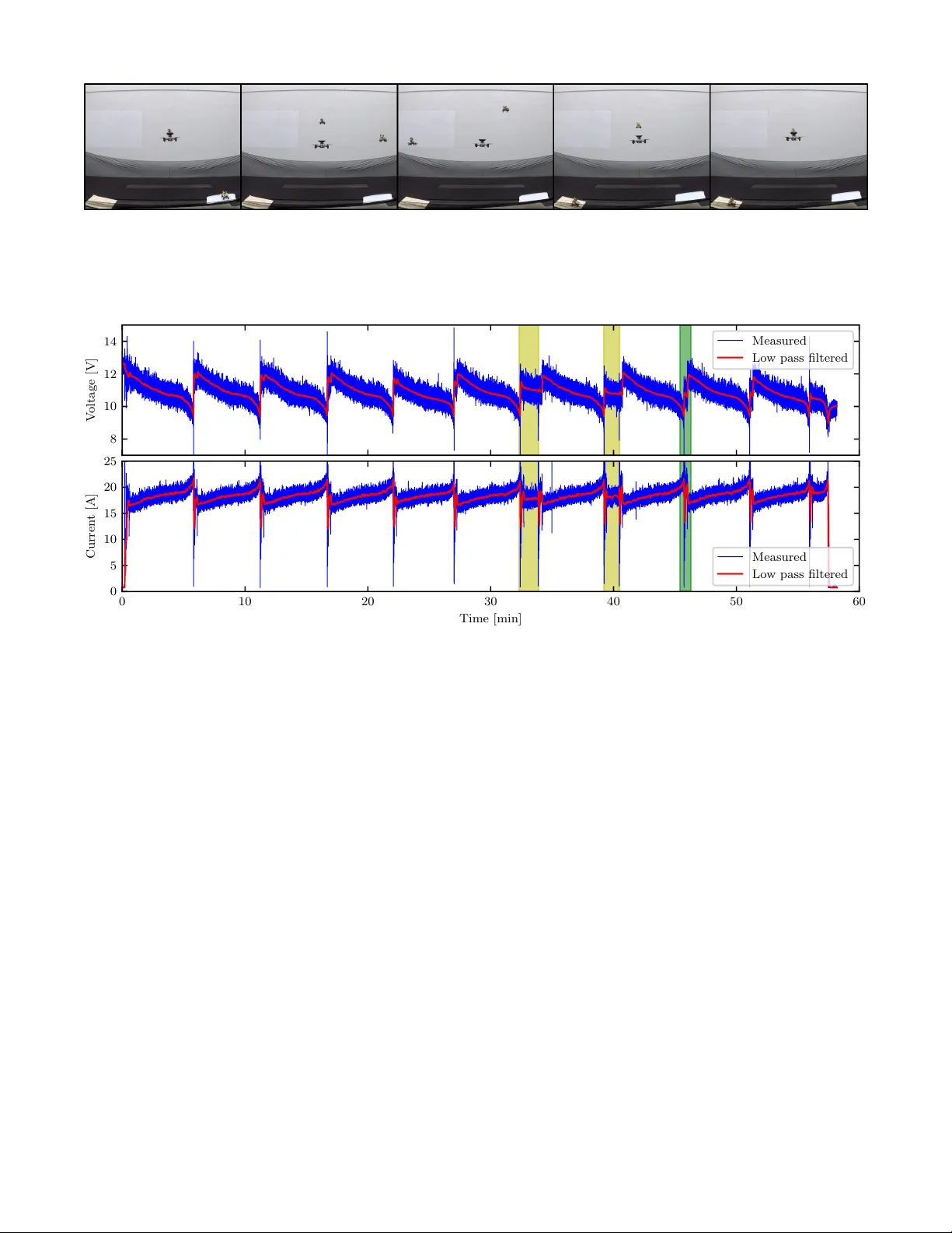
Flying batteries: In-flight battery switching to incr ease multir otor flight time Karan P . Jain and Mark W . Mueller Abstract — W e present a no vel approach to increase the flight time of a multirotor via mid-air docking and in-flight battery switching. A main quadcopter flying using a primary battery has a docking platform attached to it. A ‘flying battery’ – a small quadcopter carrying a secondary battery – is equipped with docking legs that can mate with the main quadcopter’ s platform. Connectors between the legs and the platform estab- lish electrical contact on docking, and enable power transfer from the secondary battery to the main quadcopter . A custom- designed circuit allo ws arbitrary switching between the primary battery and secondary battery . W e demonstrate the concept in a flight experiment in volving repeated docking, battery switching, and undocking . This is shown in the video attachment 1 . The experiment increases the flight time of the main quadcopter by a factor of 4 . 7 × compared to solo flight, and 2 . 2 × a theoretical limit for that given multirotor . Importantly , this increase in flight time is not associated with a large increase in overall vehicle mass or size, lea ving the main quadcopter in fundamentally the same safety class. I . I N T RO D U C T I O N Multirotors are frequently employed in mapping, delivery , monitoring, search and rescue missions [1]–[4] among many other applications o wing to their ability to hover . Ho wever , multirotors inherently have lower endurance and range as compared to fixed-wing aircraft [5]. There is a growing demand for higher endurance and range in multirotors with their increasing usage in the research and industrial setting. Current literature cov ers innov ative methods to increase the endurance of multirotors. A hybrid aerial vehicle is presented in [6] which exploits the efficiency of a fixed-wing and hov ering ability of a multirotor . An online strategy for optimizing efficiency by altering flight parameters over a tra- jectory is presented in [7]. An approach without attempting to increase efficienc y is to have a recharging station for a quadcopter , demonstrated for example in [8]. As recharging is substantially slo wer than con ventional refuelling, instead a discharged battery may be swapped with a char ged one. Battery swapping at a ground station has been sho wn in [9]– [11]. One limitation of ground-based swapping stations is an interruption to the mission. For example, if a quadcopter’ s mission is monitoring a target, then going to a ground station for battery replacement results in a mission failure. A spare battery ha ving the ability to fly to the quadcopter will enable an uninterrupted mission. This capability can be enhanced if the spare battery can be remov ed in-flight Authors are with the High Performance Robotics Laboratory (HiPeRLab) at the Department of Mechanical Engineering, UC Berkeley , CA 94720, USA. { karanjain, mwm } @berkeley.edu 1 The explanation and experimental validation video can be found here: https://youtu.be/PpJIo4HXl_Q Fig. 1: A flying battery (above) about to dock on the main quadcopter (below). after discharging so that another spare battery can take its place and continue providing energy . Moreov er , this would allow a system to operate for long-distance flights without the disruption of stopping the flight, potentially a crucial feature to applications such as urban air mobility . W e present the concept of a ‘flying battery’ – a secondary battery mounted on a small quadcopter . While a main quad- copter performs some task mid-air using a primary battery , a flying battery can fly to wards the main quadcopter and dock on it. The main quadcopter can then switch its po wer source to the secondary battery . Once the flying battery is depleted, it can undock, and another fully charged flying battery can dock in its place. This process can be repeated until the primary battery , which is only used from the time when one flying battery undocks until another one docks back, is depleted. This increases the total flight time and is achiev ed while the main quadcopter is airborne, so there is no interruption to the mission. Fig. 1 shows a flying battery approaching the main quadcopter to dock on it. The paper is organized as follows. Section II presents a fundamental flight time vs. battery mass analysis to motiv ate the usage of our proposed system. Section III explains the hardware design of our system. Section IV covers the method of docking a flying battery on the main quadcopter and undocking it. Section V demonstrates how our design increases the flight time of the main quadcopter . I I . M OT I V A T I O N In this section, we present an analysis of a fundamental limitation of ho vering battery-po wered multirotors. Specifi- 0 . 0 0 . 2 0 . 4 0 . 6 0 . 8 1 . 0 Battery mass fraction of total mass ( φ ) 0 . 0 0 . 2 0 . 4 0 . 6 0 . 8 1 . 0 Normalized fligh t time ( T fligh t ) Fig. 2: Effect of battery mass on normalized hovering flight time. After the peak at φ = 2 3 , a larger battery reduces flight time. cally , we sho w that the achiev able flight time only increases up to a certain point, as more battery is used on a v ehicle. W e model the aerodynamic po wer consumption p i of an individual propeller i to be related to its thrust f i as p i ∝ f 3 2 i (1) This can be derived from actuator disk theory [12], or from mechanical analysis of hub torque and rotational speed [13]. Assuming constant energy density γ , the total available energy E batt in a battery will be γ times the battery’ s mass. Let m 0 be the mass of all components of the multirotor , excluding the battery , and let φ be the fraction of the total vehicle mass that is the battery mass, so that the total vehicle mass is 1 1 − φ m 0 and the battery mass is φ 1 − φ m 0 . For a hovering multirotor , the indi vidual propeller thrusts scale proportionally with the v ehicle’ s total mass. The elec- tric power draw p elec can be written as, p elec = k p 1 1 − φ m 0 3 / 2 (2) where k p is determined by propeller design, gravitational acceleration, and powertrain efficiency . W e assume these parameters are constant for a given vehicle. The av ailable flight time T flight can then be related to the vehicle mass m 0 , and battery mass fraction: T flight = E batt p elec = γ φ 1 − φ m 0 k p 1 1 − φ m 0 3 / 2 ∝ φ √ 1 − φ √ m 0 (3) This relationship is plotted in Fig. 2, showing that vehicles with relativ ely small batteries expect to see a strong improve- ment in total flight time with increasing battery mass, until a peak where the battery takes up two-thirds of the vehicle’ s mass. W e note that the location of this peak is independent of γ and k p . This large fraction makes structural design difficult and may lead to potential safety concerns. This analysis motiv ates our proposed system – by creating a system that enables the multirotor to “shed” a discharged battery , and replace it with a fully charged battery , the vehicle is able to exceed the flight-time limitation imposed by (3). I I I . D E S I G N In this section, we explain the design of the mid-air docking mechanism, the battery switching circuit, and the quadcopters used in our experiments. A. Docking mechanism Mid-air docking of multirotors has been performed using a variety of mechanisms. Robotic hands, a winch, and a rod were used by [14] to dock vehicles vertically aligned. Lateral docking using magnets has been demonstrated in [15]. Our proposed solution uses a mechanical guide structure in the form of a landing platform on the main quadcopter and landing legs on the flying battery as shown in Fig. 3. This en- ables a fast docking procedure along with an easy undocking process. This design achie ves the following objectiv es: • No active components: The mechanism does not con- sume power , and uses the weight of the flying battery for docking. This makes it light-weight and leads to a simple undocking process – regular take-off. • Docks vertically aligned: The flying battery does not produce any thrust when docked. Aligning the center of mass of the docked configuration along the thrust direction of the main quadcopter prev ents unbalanced thrusts and additional po wer consumption. • Pr ecision landing: W e require a secure electrical contact after docking to power the main quadcopter from the flying battery . This necessitates the electrical connectors to be well aligned. Fig. 3: T op: Main quadcopter with the docking platform and spring loaded connectors. Bottom: Flying battery with the docking legs and copper plate connectors. The docking platform and the legs include electrical con- nectors which can allow the transfer of power from a flying battery to the main quadcopter . The docking mechanism allows some lateral play between the vehicles to facilitate smooth docking and undocking, but this play is limited sufficiently to ensure that the electrical connections are not broken due to vibrations and dynamic motions. The increased mass and moment of inertia of the main quadcopter in the docked configuration reduces its agility . Howe ver , it can still perform moderately agile motion while maintaining electrical contact, e ven without an activ e fix- ing mechanism. This can be analyzed by computing the required friction for zero relativ e acceleration between the two vehicles when docked. W e assume, for simplicity , that rotary motion is negligible, and that the only forces acting on the main quadcopter are its weight, total thrust from the propellers f T , and the normal f N and friction f f force at the docking mechanism, as is shown in Fig. 4. The flying battery is acted upon by its weight, and the normal and friction forces from the docking mechanism (equal and opposite to those acting on the main quadcopter). The v ector of gravity is g . Letting m m and m f b respectiv ely be the mass of the main quadcopter and the flying battery , we can compute the requirement for zero relative acceleration by applying Newton’ s law , where a m and a f b are the acceleration of the main quadcopter and flying battery , respectively: 0 = a m − a f b (4) = m m g + f T + f N + f f m m − m f b g − f N − f f m f b (5) = f T m m + f N m m + m f b m m m f b + f f m m + m f b m m m f b (6) Because the body-fix ed thrust direction is normal to the docking platform, the forces f T and f N are parallel, and perpendicular to f f . As long as the thrust produced by the main quadcopter is positive (as w ould be true under almost all flight conditions), the normal force at the platform will act into the platform (ensuring electrical contact), and no friction force is required for the vehicles to remain docked. In reality , there will be additional forces acting on the system, such as aerodynamic drag during translation. In such cases, the required friction force is non-zero. Large angular v elocities or angular accelerations may lead to loss of normal force. Howe ver , placing the docking platform close to the main quadcopter’ s center of mass makes this unlik ely to occur . B. Battery switc hing cir cuit A crucial feature of our design is seamless switching between the primary battery and secondary battery . Since our system is flying, we cannot af ford to cut the po wer supply during this switch. The two batteries need to be connected in parallel for some time to achiev e this, and this is only safe within a voltage difference of 0 . 2 V per cell for lithium polymer (LiPo) batteries. This would often not be the case in our application because we intend to utilize the secondary battery from a fully charged state ( 4 . 2 V per cell) to a completely discharged state ( 3 . 0 V per cell). W e solve this by connecting diodes in series with each of the batteries to av oid - Flying battery Main quadcopter - Fig. 4: Free body diagram of the two vehicles when docked G P IO P rim a ry b a t tery Se con da ry b a t tery D iod e1 D iod e2 R ela y C oil T o m a in qu ad co p te r Fig. 5: Schematic of the battery switching circuit. rev erse currents. W e utilize smart bypass diodes because they hav e a much lower v oltage drop than con ventional P- N junction or Schottk y diodes. At our operating current of about 18 A , the v oltage drop is less than 0 . 1 V . A normally closed relay is connected in series with the primary battery . By opening the switch, we can draw power from the secondary battery ev en when it is at a lo wer voltage than the primary battery . The relay coil is connected across the secondary battery input leads in series with a MOSFET . This ensures that the switch does not open without a secondary battery , and allows us to use a GPIO pin on the flight controller to control the switch. Fig. 5 shows a schematic diagram of the battery switching circuit. C. V ehicle design 1) Main quadcopter: The main quadcopter is designed to ha ve enough payload capacity for carrying useful sensors such as surveillance cameras, or environmental sensors. The battery switching circuit and docking platform are stacked on top of the main quadcopter . Spring-loaded connectors are mounted on the docking platform to serve as input leads to the quadcopter from the secondary battery . The primary battery is a 3S 2 . 2 Ah LiPo battery , which weighs 190 g . 2) Flying battery: The small quadcopter is designed to hav e suf ficient payload capacity to carry a secondary battery for the main quadcopter . The docking legs for the small quad- copter are designed to minimize blockage of the propeller airflow to minimally affect the payload capacity . Copper plates of dimensions similar to the spring-loaded connectors are installed on the legs to serve as the secondary battery output leads. The small quadcopter is powered using a 2S 0 . 8 Ah LiPo battery weighing 45 g . The secondary battery is a 3S 1 . 5 Ah LiPo battery , which weighs 135 g . T able I summarizes the specifications of the two vehicles. T ABLE I: Specifications of quadcopters used in experiments Parameter Main quadcopter Flying battery Propeller diameter 203 mm 76 mm Arm length 165 mm 58 mm Mass 820 g 320 g Maximum thrust 27 N 8 N I V . D O C K I N G M A N E U V E R This section covers the considerations in volv ed in docking and undocking the flying battery and the main quadcopter . A. Aer odynamic disturbance r ejection A critical consideration for docking two quadcopters mid- air is the mutual aerodynamic interference caused by the airflow of the tw o vehicles, especially during vertical docking because one quadcopter is directly in the downwash of another . An analysis of rotorcraft do wnwash is presented in [16], [17]. Detailed characterization and analysis of aerody- namic forces and torques between two quadcopters is shown in [18]. W e will use the follo wing k ey results from [18]: 1) The ef fect of mutual aerodynamic disturbances is pri- marily seen on the quadcopter that flies below . The quadcopter that flies abov e is negligibly affected. 2) The predominant component of the aerodynamic forces is along the direction of the downwash. Forces perpen- dicular to the direction of the downwash can be ignored. 3) The aerodynamic torques disturb the bottom quadcopter in a way that tends to v ertically align it with the top quadcopter . This is advantageous in our maneuver . Hence, we do not attempt to reject the torques. W e chose to fly the flying battery abov e the main quad- copter o wing to result (1). The main quadcopter has suf ficient thrust capacity to reject the disturbances caused by the flying battery’ s airflow . Based on results (2) and (3), the only disturbance that we correct for is the vertical force. This is done by applying a feedforward thrust based on the relative location of the two quadcopters. The feedforward thrust map is created by flying the two quadcopters at various relativ e separations. A PID controller is used for position control which outputs a desired total thrust force. The map is created from previous runs’ con- troller integral actions and tested on subsequent runs until satisfactory disturbance rejection is achiev ed. B. Docking trajectory The key requirement of this project is that the main quad- copter should not ha ve to mov e substantially from its place during a long-term operation. Therefore, the docking trajec- tory in volv es minimal motion of the main quadcopter . Result (3) in Section IV -A mentions that aerodynamic torques tend to vertically align the two quadcopters. Based on this, we start by commanding the flying battery to go 30 cm vertically abov e the docking platform on the main quadcopter . It is then commanded to descend towards the docking platform. In this phase, any misalignments and tracking errors are corrected by the aerodynamic torque on the main quadcopter . Once the flying battery’ s center is within 2 . 0 cm of the docking platform’ s center in the horizontal plane, and the bottom surface of its legs is within 5 . 0 cm of the platform’ s surface, it is commanded to free fall. The docking platform is designed to precisely align the flying battery’ s connectors with those on the main quadcopter once the y are within a 2 . 0 cm radius in the horizontal plane. The drop height of 5 . 0 cm was chosen to hav e suf ficient impact for the flying battery to slide in and align correctly , and also a void rebound- ing which might cause misalignment. Fig. 1 sho ws a picture of the flying battery about to dock on the main quadcopter . Starting from takeof f, it takes 20 - 25 s for the flying battery to dock on the main quadcopter . These distances and times were experimentally determined to gi ve satisfactory results. For undocking, we command the flying battery to takeoff from the docking platform and go straight up to a position 30 cm abov e the platform. After this, the flying battery lands and another one is free to dock on the main quadcopter . Including landing, this maneuver takes approximately 8 s . V . E X P E R I M E N T A L V A L I D A T I O N W e validate the use of our design by conducting an experiment in volving repeated docking, battery switching, and undocking so that the main quadcopter’ s use of the primary battery is only limited to the undocking and docking phases. Whenev er a flying battery is docked correctly , we use the secondary battery to power the main quadcopter . A. Experimental setup The quadcopters used in our experiments are localized via sensor fusion of a motion capture system and an onboard rate gyroscope. Experimental data from the motion capture system, v oltage sensor , and current sensor are logged via radio for post-processing. W e control the quadcopters using a cascaded PID position and attitude controller shown in Fig. 6. The integral action on the position and yaw helps prev ent steady state errors and ensures that the vehicles are correctly vertically aligned. Additionally , feedforward thrust for the main quadcopter to reject aerodynamic disturbances is directly added to the total thrust based on the relati ve location of the flying battery with respect to the main quadcopter . Thrust conversion Attitude control Position control Desired attitude Body torques T otal thrust V ehicle states Desired position Propeller thrusts Relative position F eedforward thrust + Fig. 6: Block diagram of the quadcopter controller . The flying battery does not have the feedforward thrust component. Fig. 7: Steps (4)-(6) of the demonstration. From left to right, (a) main quadcopter hovers with a flying battery docked on it, (b) the first flying battery is depleted, so it undocks and another fully charged flying battery takes off, (c) the second flying battery mov es towards the main quadcopter to dock and first flying battery begins landing, (d) second flying battery descends to dock on the main quadcopter , (e) second flying battery is docked on the main quadcopter (which continues to hover) and first flying battery has landed - we now manually replace the discharged flying battery with a fully charged one. 8 10 12 14 V oltage [V] Measured Lo w pass filtered 0 10 20 30 40 50 60 Time [min] 0 5 10 15 20 25 Curren t [A] Measured Lo w pass filtered Fig. 8: Input v oltage and current vs. time of the main quadcopter for the demonstration. Lo w pass filtered data is also plotted for ease of visualization. The maximum current value of 55 A is cut off in the plot. Regions highlighted in yellow show parts of the experiment where the flying battery did not make electrical contact after docking. Fig. 9 shows a zoomed-in version of the green highlighted region. B. Demonstration T o demonstrate the ability and flight time benefit of our design, we conduct the following experiment: 1) The main quadcopter takes of f with a fully charged primary battery and ho vers at a specific desired position. 2) A fully charged flying battery is commanded to dock on the main quadcopter . 3) Once dock ed, the main quadcopter switches its power source to the secondary battery and continues hovering. 4) Once the secondary battery is completely discharged, the main quadcopter switches back to primary battery . 5) The flying battery is commanded to undock and land on the ground. Simultaneously , another fully charged flying battery tak es off. 6) The second flying battery docks on the main quadcopter and we again switch to the secondary battery . 7) During this period, we manually replace the discharged flying battery with a fully charged one. 8) This process is repeated until the primary battery of the main quadcopter , only consumed during the undocking and docking process, is completely discharged. Fig. 7 shows steps (4)-(6) of the procedure. In this demonstration, the main quadcopter hovered for a total time of 57 min . Ho vering time of the main quadcopter flying alone without the dock-switch-undock-repeat process is 12 min . C. Discussion The plots of input voltage and current vs. time of the main quadcopter for the duration of the entire demonstration are sho wn in Fig. 8. W e see the characteristic LiPo battery discharge curve [19] several times in the voltage vs. time plot. Each shows the complete energy consumption of one secondary battery . The current vs. time plot sho ws that current input to the quadcopter increases as the voltage decreases. This is expected because the power consumption of the quadcopter must remain approximately constant to hov er continuously . The re gions in Fig. 8 highlighted in yellow show the parts of the experiment where the secondary battery did not connect to the circuit after docking. In those regions, the main quadcopter continues using the primary battery . W e command the incorrectly docked flying battery to undock and another fully charged flying battery to dock. A typical undocking and docking maneuv er part is high- lighted in green on the plot and a zoomed-in version of 8 10 12 14 V oltage [V] 45 . 6 45 . 7 45 . 8 45 . 9 46 . 0 46 . 1 Time [min] 0 5 10 15 20 25 Curren t [A] Fig. 9: Zoomed version of green highlighted region in Fig. 8 show- ing the input voltage, current, and power of the main quadcopter during undocking and docking. Dotted lines mark the following ev ents: (i) black: main quadcopter switches to primary battery , (ii) green: flying battery undocks, (iii) red: another flying battery docks. that re gion is shown in Fig. 9. When the main quadcopter switches back to the primary battery , the input voltage jumps to the primary battery voltage. If the relay is closed, the main quadcopter draws power from the battery which is at a higher voltage. The flying battery then undocks. A current (and hence, power) surge is observed because the main quadcopter is now rejecting aerodynamic forces. This is followed by the flying battery moving out and landing. In this part, the main quadcopter is flying without any additional mass or aerodynamic disturbances and hence we observe a dip in power consumption. A few seconds later, another fully charged flying battery flies on top of the main quadcopter and begins descending to dock. W e again observe an increase in power consumption because of aerodynamic force rejection. Lastly , the flying battery docks on the main quadcopter . W e see another jump in voltage because the secondary battery is fully charged, and at a higher voltage than the primary battery . Po wer consumption now settles around a value needed for hovering in the docked configuration. The reliability of the docking contact under maneuvering, as analyzed in Section III-A, was tested by flying the main quadcopter powered by the flying battery in an oscillating motion with peak lateral accelerations of 12 m s − 2 without losing contact. This is shown in the attached video. From T able I the fraction of the main quadcopter’ s total mass from the battery is φ ≈ 0 . 23 , with the vehicle’ s base mass m 0 = 630 g . The vehicle’ s flight time is approximately 12 min . Referring to Fig. 2, this mass fraction corresponds to a total flight time of approx. 0.47 times the optimal flight time achiev able for this vehicle. Thus, an “optimal” design would be capable of a maximum flight of 25 . 6 min . This design would howe ver require a battery of 1 . 26 kg for a total vehicle mass of 1 . 89 kg , increasing the vehicle’ s overall mass by more than a factor of tw o. The flying battery concept is thus able to carry the vehicle payload for a flight more than twice as long as the theoretical limit, while maintaining the total vehicle mass lo w , thus resulting in a safer , more useful vehicle. V I . C O N C L U S I O N S In this paper , we ha ve introduced the concept and design of a flying battery - a small quadcopter that can carry a secondary battery for a main quadcopter , dock on it, allo w it to switch its power supply from the primary battery to the secondary battery and back, and undock from it. W e designed a passi ve mid-air docking mechanism in the form of docking legs on the flying battery which mate with a docking platform on the main quadcopter . W e also designed a battery switching mechanism to seamlessly switch the power source of the main quadcopter mid-flight. This was achiev ed using diodes to av oid backflow of current into batteries, a relay to turn the primary supply off or on, and spring loaded connectors and copper plates for electrical connection to draw power from the secondary battery . W e utilized an empirical model to pro vide a feedforw ard thrust from the main quadcopter to reject the aerodynamic disturbance forces due to the downw ash of the flying battery . Lastly , we demonstrated the ability of the system to dock, switch batteries, and undock multiple times in a single flight. This helped the main quadcopter achiev e a flight time of 57 min as compared to its solo flight of 12 min . This is a 4.7-fold increase in the flight time, and a 2 . 2 × increase ov er the theoretical flight time limit, all while keeping the vehicle in essentially the same safety class. This can be e xtremely useful in, for example, continuous monitoring activites. An extension to this work is to redesign the onboard circuitry to make secondary batteries rechar ge the primary battery . This removes the constraint of fully discharging the primary battery and, in principle, should give us unlimited flight time. The ne w constraint would be the number of charging cycles that the primary battery can handle. Another extension is exploring range extension with this concept, including the more complex challenge of docking and undocking while the main quadcopter is moving. A third extension is to use only on-board sensing for the docking, rather than relying on an e xternal motion capture system as done in the demonstrations in this paper . Absolute localization may be performed via sensor fusion of INS and GPS [20]. A camera mounted on the main quadcopter and markers pasted on the flying batteries may be used for computer vision based localization [21], [22] as it offers high precision relativ e localization suitable for the sensiti ve docking and undocking maneuvers. A C K N O W L E D G M E N T W e gratefully ackno wledge financial support from NA VER LABS. The experimental testbed at the HiPeRLab is the result of contributions of man y people, a full list of which can be found at hiperlab.berkeley.edu/members/ . The authors wish to acknowledge Minos Park for assisting with the e xperimental v alidation. R E F E R E N C E S [1] S. Sharma, A. Muley , R. Singh, and A. Gehlot, “U A V for surv eil- lance and environmental monitoring, ” Indian Journal of Science and T echnology , vol. 9, no. 43, 2016. [2] S. W aharte and N. T rigoni, “Supporting search and rescue operations with UA Vs, ” in 2010 International Confer ence on Emerging Security T echnologies (EST) . IEEE, 2010, pp. 142–147. [3] M. Erdelj, E. Natalizio, K. R. Chowdhury , and I. F . Akyildiz, “Help from the sky: Leveraging uavs for disaster management, ” IEEE P er- vasive Computing , vol. 16, no. 1, pp. 24–32, 2017. [4] J. Cacace, A. Finzi, V . Lippiello, M. Furci, N. Mimmo, and L. Mar- coni, “ A control architecture for multiple drones operated via mul- timodal interaction in search & rescue mission, ” in 2016 IEEE International Symposium on Safety , Security , and Rescue Robotics (SSRR) . IEEE, 2016, pp. 233–239. [5] M. Boon, A. Drijfhout, and S. T esfamichael, “Comparison of a fixed- wing and multi-rotor uav for environmental mapping applications: A case study , ” The International Ar chives of Photogrammetry , Remote Sensing and Spatial Information Sciences , vol. 42, p. 47, 2017. [6] H.-P . Thamm, N. Brieger , K. Neitzke, M. Meyer , R. Jansen, and M. M ¨ onninghof, “Songbird-an innovati ve uas combining the adv an- tages of fixed wing and multi rotor uas. ” International Ar chives of the Photogr ammetry , Remote Sensing & Spatial Information Sciences , vol. 40, 2015. [7] A. T agliabue, X. Wu, and M. W . Mueller, “Model-free online motion adaptation for optimal range and endurance of multicopters, ” in 2019 International Conference on Robotics and Automation (ICRA) . IEEE, 2019, pp. 5650–5656. [8] A. Junaid, A. Konoik o, Y . Zweiri, M. Sahinkaya, and L. Seneviratne, “ Autonomous wireless self-charging for multi-rotor unmanned aerial vehicles, ” Ener gies , vol. 10, no. 6, p. 803, 2017. [9] D. Lee, J. Zhou, and W . T . Lin, “ Autonomous battery swapping system for quadcopter , ” in 2015 International Confer ence on Unmanned Air craft Systems (ICU AS) . IEEE, 2015, pp. 118–124. [10] T . T oksoz, J. Redding, M. Michini, B. Michini, J. P . How , M. V avrina, and J. V ian, “ Automated battery swap and recharge to enable persistent uav missions, ” in AIAA Infotech@ Aer ospace Conference , vol. 21, 2011. [11] N. K. Ure, G. Chowdhary , T . T oksoz, J. P . How , M. A. V avrina, and J. V ian, “ An automated battery management system to enable persis- tent missions with multiple aerial vehicles, ” IEEE/ASME transactions on mechatr onics , vol. 20, no. 1, pp. 275–286, 2014. [12] B. W . McCormick, “ Aerodynamics aeronautics and flight mechanics, ” 1995. [13] C. Holda, B. Ghalamchi, and M. W . Mueller, “T ilting multicopter rotors for increased power ef ficiency and yaw authority , ” in 2018 International Confer ence on Unmanned Air craft Systems (ICU AS) . IEEE, 2018, pp. 143–148. [14] R. Miyazaki, R. Jiang, H. Paul, K. Ono, and K. Shimonomura, “ Air- borne docking for multi-rotor aerial manipulations, ” in 2018 IEEE/RSJ International Conference on Intellig ent Robots and Systems (IROS) . IEEE, 2018, pp. 4708–4714. [15] D. Saldana, B. Gabrich, G. Li, M. Y im, and V . Kumar , “Modquad: The flying modular structure that self-assembles in midair, ” in 2018 IEEE International Confer ence on Robotics and Automation (ICRA) . IEEE, 2018, pp. 691–698. [16] D. Y eo, E. Shrestha, D. A. Paley , and E. M. Atkins, “ An empirical model of rotorcraft uav downw ash for disturbance localization and av oidance, ” in AIAA Atmospheric Flight Mechanics Conference , 2015, p. 1685. [17] S. Y oon, H. C. Lee, and T . H. Pulliam, “Computational analysis of multi-rotor flows, ” in 54th AIAA Aer ospace Sciences Meeting , 2016, p. 0812. [18] K. P . Jain, T . Fortmuller, J. Byun, S. A. M ¨ akiharju, and M. W . Mueller , “Modeling of aerodynamic disturbances for proximity flight of mul- tirotors, ” in 2019 International Conference on Unmanned Air craft Systems (ICUAS) . IEEE, 2019, pp. 1261–1269. [19] N. Navarathinam, R. Lee, and H. Chesser, “Characterization of lithium-polymer batteries for cubesat applications, ” Acta Astr onautica , vol. 68, no. 11-12, pp. 1752–1760, 2011. [20] A. Nemra and N. Aouf, “Robust ins/gps sensor fusion for uav localization using sdre nonlinear filtering, ” IEEE Sensors Journal , vol. 10, no. 4, pp. 789–798, 2010. [21] M. F . Sani and G. Karimian, “ Automatic navigation and landing of an indoor ar. drone quadrotor using aruco marker and inertial sensors, ” in 2017 International Conference on Computer and Drone Applications (IConD A) . IEEE, 2017, pp. 102–107. [22] J. Bacik, F . Durovsky , P . Fedor , and D. Perduko va, “ Autonomous flying with quadrocopter using fuzzy control and aruco markers, ” Intelligent Service Robotics , vol. 10, no. 3, pp. 185–194, 2017.
Original Paper
Loading high-quality paper...
Comments & Academic Discussion
Loading comments...
Leave a Comment