An Interactive LiDAR to Camera Calibration
Recent progress in the automated driving system (ADS) and advanced driver assistant system (ADAS) has shown that the combined use of 3D light detection and ranging (LiDAR) and the camera is essential for an intelligent vehicle to perceive and understand its surroundings. LiDAR-camera fusion requires precise intrinsic and extrinsic calibrations between the sensors. However, due to the limitation of the calibration equipment and susceptibility to noise, algorithms in existing methods tend to fail in finding LiDAR-camera correspondences in long-range. In this paper, we introduced an interactive LiDAR to camera calibration toolbox to estimate the intrinsic and extrinsic transforms. This toolbox automatically detects the corner of a planer board from a sequence of LiDAR frames and provides a convenient user interface for annotating the corresponding pixels on camera frames. Since the toolbox only detects the top corner of the board, there is no need to prepare a precise polygon planar board or a checkerboard with different reflectivity areas as in the existing methods. Furthermore, the toolbox uses genetic algorithms to estimate the transforms and supports multiple camera models such as the pinhole camera model and the fisheye camera model. Experiments using Velodyne VLP-16 LiDAR and Point Grey Chameleon 3 camera show robust results.
💡 Research Summary
This paper addresses the critical need for accurate LiDAR‑camera calibration in autonomous driving and advanced driver‑assistance systems, where the fusion of 3‑D LiDAR point clouds with 2‑D camera imagery enables robust perception. Existing calibration techniques largely rely on planar targets such as checkerboards and assume that sufficient LiDAR points fall on the target surface. These assumptions break down for long‑range outdoor scenarios because (i) low vertical resolution of typical 16‑line LiDARs yields sparse returns on distant boards, and (ii) the rigidity and flatness of cardboard or wooden boards cannot be guaranteed under field conditions. Consequently, many state‑of‑the‑art methods fail to find reliable LiDAR‑camera correspondences beyond a few meters.
The authors propose an interactive calibration toolbox that circumvents these limitations by (1) automatically detecting the highest corner of a planar board in a sequence of LiDAR frames, and (2) allowing a user to annotate the corresponding pixel in the synchronized camera image. Because only the top corner is required, the board does not need to be a perfect checkerboard; a simple polygonal board with one vertex pointing upward suffices. The detection algorithm works as follows: the user defines a region of interest (ROI); for each LiDAR frame the algorithm extracts points inside the ROI, computes the vertical line with the greatest height difference, and checks whether that line contains a single point. If so, the point is stored as a 3‑D corner; otherwise the frame is discarded. This process yields a set of reliable 3‑D points even when the board is only partially scanned.
Once a set of 3‑D corners is collected, the toolbox presents the corresponding camera frame (chosen as the nearest‑in‑time frame) and asks the user to click the pixel that represents the same physical corner. The resulting 3‑D‑2‑D correspondences are fed into a calibration optimizer that simultaneously solves for extrinsic parameters (rotation α, β, γ and translation u₀, v₀, w₀) and intrinsic camera parameters. The toolbox supports both the classic pinhole model (fₓ, f_y, cₓ, c_y) and a fisheye model that adds radial and tangential distortion coefficients (α_c, k₁…k₅).
To avoid the pitfalls of gradient‑based solvers (local minima, sensitivity to initial guess), the authors employ a genetic algorithm (GA). An initial parameter set and bounded search ranges are defined; five parallel GA “slots” each evolve a population of 800 individuals over 30 generations. The fitness function is the average pixel reprojection error of the projected LiDAR corners onto the image plane. After each GA iteration, the search bounds are tightened around the best solution, and the process repeats until the error no longer improves. This global‑search strategy enables robust convergence for the highly non‑linear fisheye model as well as the simpler pinhole case.
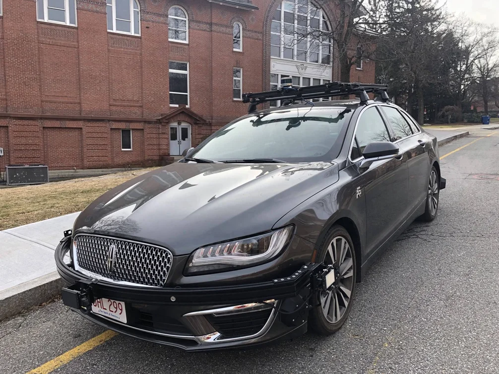
Experimental validation was performed on a real vehicle (Lincoln MKZ) equipped with a Velodyne VLP‑16 LiDAR (16 vertical beams, 0.2° vertical resolution, 2° horizontal resolution) and a Point Grey Chameleon‑3 camera mounted on the roof. A 2 × 3 ft board was rotated 45° so that one vertex faced upward; a person moved the board within a 10 m × 30 m area in front of the vehicle. Over a 219‑second recording, 11 582 camera frames and 7 639 LiDAR frames were captured, yielding 222 valid LiDAR‑camera correspondences after processing. A separate validation sequence provided 358 additional correspondences.
Using the pinhole model, the toolbox achieved an average reprojection error of 6.35 pixels on the training set and 6.75 pixels on the test set. With the fisheye model, the errors were 5.02 pixels (training) and 5.10 pixels (test). Error distribution analysis showed that points near the camera optical axis exhibited small offsets, while points at larger incidence angles suffered errors up to 16 pixels, indicating that the current intrinsic models may not fully capture extreme lens distortion. To further demonstrate practical utility, the calibrated transformation was applied to project LiDAR‑detected lane markers onto camera images during a road test; the projected lanes aligned well with the visual lane markings, confirming the calibration’s applicability to downstream perception tasks.
Key contributions of the work are:
- A corner‑only detection scheme that works with sparse LiDAR data and eliminates the need for high‑precision planar targets.
- An interactive yet lightweight user interface that requires only a single click per frame, dramatically reducing manual effort.
- A GA‑based global optimizer capable of handling both pinhole and fisheye intrinsic models, providing robustness against local minima.
- Demonstrated calibration accuracy at ranges up to 30 m, far beyond the typical 5 m limit of prior indoor‑oriented methods.
Future directions identified by the authors include refining the fisheye distortion model to reduce angular‑dependent errors, integrating precise hardware time‑stamping for tighter LiDAR‑camera synchronization, and automating the 2‑D annotation step using deep‑learning‑based object detection. Such extensions would move the toolbox toward fully automatic, real‑time calibration suitable for large‑scale autonomous fleets and other robotics platforms that rely on multi‑sensor fusion.
Comments & Academic Discussion
Loading comments...
Leave a Comment