Radiation Pattern Synthesis Using Hybrid Fourier- Woodward-Lawson-Neural Networks for Reliable MIMO Antenna Systems
In this paper, we implement hybrid Woodward-Lawson-Neural Networks and weighted Fourier method to synthesize antenna arrays. The neural networks (NN) is applied here to simplify the modeling of MIMO antenna arrays by assessing phases. The main proble…
Authors: Elies Ghayoula, Ridha Ghayoula, Jaouhar Fattahi
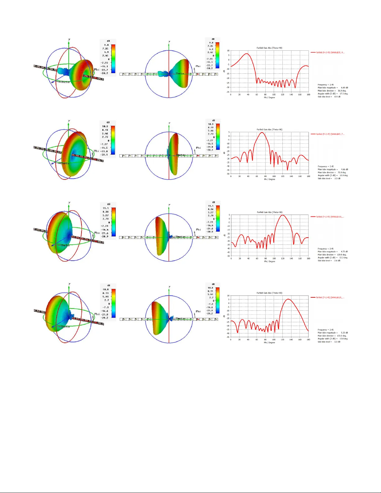
Radiation P attern Synthesis Using Hybrid F ourier - W oodward-La wson-Neural Netw orks for Reliable MIMO Antenna Systems Elies Ghayoula 1 , 2 , Ridha Ghayoula 2 , Jaouhar Fattahi 3 , Emil Pricop 4 , Jean-Yves Chouinard 2 and Ammar Bouallegue 1 1 Sys’Com Laboratory , National Engineering School of T unis, ENIT , T unis El Manar Univ ersity , T unisia. 2 Department of Electrical and Computer Engineering, Lav al University , Quebec, Canada. 3 Department of Computer Science and Software Engineering, La val Uni versity , Quebec, Canada. 4 Automatic Control, Computers and Electronics Department Petroleum-Gas Univ ersity of Ploiesti, Romania. Abstract —In this paper , we implement hybrid W oodward- Lawson-Neural Networks and weighted Fourier method to syn- thesize antenna arrays. The neural networks (NN) is applied here to simplify the modeling of MIMO antenna arrays by assessing phases. The main problem is obviously to find optimal weights of the linear antenna array elements giving radiation pattern with minimum sidelobe lev el (SLL) and hence ameliorating the antenna array performance. T o attain this purpose, an antenna array f or reliable Multiple-Input Multiple-Output (MIMO) ap- plications with frequency at 2.45 GHz is implemented. T o v alidate the suggested method, many examples of unif ormly excited array patterns with the main beam are put in the direction of the useful signal. The W oodward-Lawson-Neural Networks synthesis method permits to find out interesting analytical equations for the synthesis of an antenna array and highlights the flexibility between the system parameters in input and those in output. The performance of this hybrid optimization underlines how well the system is suitable for a wireless communication and how it participates in reducing interference, as well. I . I N T R O D U C T I O N Antenna array are lar gely used in applications including satellites, wireless communications, MIMO systems, remote detection, radars, biomedical imaging, and so on. Pattern synthesis consists in choosing the antenna aspects such as the desired SLL, the most suitable position of the nulls, as well as the beamwidth of antenna pattern, and this is in order to reach the radiation pattern near to the optimal one. In literature, Se v- eral beamforming techniques exist. For instance, a synthesis of radiation patterns in linear arrays based on genetic algorithms (GA) is shown in [1]. In [2] the authors exhibit an SLL reduc- tion in linear array pattern synthesis based on particle swarm optimization (PSO). In the same vein, a linear array thinning based on iterati ve Fourier techniques is presented in [3]. A phase-only synthesis has also been presented in [4] to attain the most suitable radiation pattern. The criterion of nonlinearity related to antenna radiation patterns make antennas appropriate to artificial neural networks (ANN). NNs have been prov en good enough to cope with problems when the link between inputs and outputs is cumbersome and hard to formulate. They can reasonably assess a model owing to their capabilities to adapt their parameters by utilizing known input/output pairs. They are also able to provide optimal weights between neurons after recei ving a training phase. As soon as the training phase is finished, the network ready to communicate the results to the inputs. The increasing utilization of ANNs in a plethora of electromagnetic applications motiv ated its use in antenna array design in radiation optimization and synthesis contexts. The Multilayer Perceptron (MLP) is one of the oldest model of NN that implements single hidden layer . This kind of network is capable of approximating a giv en smooth nonlinear input-output mapping to an arbitrary degree of precision if a suf ficient set of hidden layer neurons is provided [5]. For instance, a phased array using T aguchi- neural networks is giv en in [6]. In [7] the authors present a usual application of back-propagation NN for synthesis and optimization of antenna array . In this paper , we are interested in presenting an adaptiv e Fourier W oodward-Lawson-Neural networks technique to synthesize of MIMO smart antennas. A contribution re garding several features is here made. The paper is organized as follows: The formulation of the synthesis problem is described in section II. Fourier W oodward-Lawson method is described in section III. ANN is implemented by simulation in section IV . V alidation using CST microwa ve studio for linear MIMO antennas array with 16 elements is provided in section V . Finally , in section VI we make some ov erall conclusions. I I . P R O B L E M F O R M U L A T I O N Our model as shwon in Fig. 1 is a linear antenna array with N isotropic elements placed symmetrically along the x- axis. The far-field F ( u ) of this model below with N antennas arranged along a periodic grid at distance d , can be expressed as the product of the array factor AF ( u ) and the embedded element pattern E F ( u ) F ( u ) = AF ( u ) E F ( u ) (1) Fig. 1. Linear antenna array . AF ( u ) = N − 1 X n =0 w n e j kndu (2) where w n is the complex weighting of the n th element of our linear array , k is the wav enumber 2 π λ , λ is the wav elength and u = cos θ where θ is the angular coordinate between far - field direction and the normal array model. Here, the problem of synthesis to be solved is to find the optimal weights (phases and amplitudes) of our model that are able to perform the radiation in desired direction by controlling the phase of each antenna with maximum SLL reduction by controlling the amplitude. I I I . H Y B R I D F O U R I E R - W O O DW A R D L AW S O N M E T H O D F O R F R E Q U E N C Y - S A M P L I N G D E S I G N The array factor with the Discrete F ourier Transform (DFT) is described with details in [8]. T o justify the use of Fourier approach with W oodw ard-Lawson method, many popular optimization algorithms are used for comparison; such as Schelkunoff [9], Dolph-Chebyshev and T aylor [10]. Here, Fourier methods giv e us the best results. Fig. 2. Comparison of optimization algorithms for our model. Fig. 2 shows the radiation patterns of Fourier method com- pared to Schelkunof f, T aylor and Dolph-Chebyshe v method. It’ s clear from results Fig. 2 that SLL here is reduced to − 30 dB and more for all optimization techniques with different values of half po wer beamwidth (HPBW) about 7 ◦ with Schelkunoff, 4 . 5 ◦ with T aylor , 8 ◦ with Dolph-Chebyshev and about 18 ◦ with Fourier . For our model with 16 antennas, optimal weights generated using Fourier method are shown in T ABLE I. all these results confirm that radiation patterns synthesis with Fourier outperform the other techniques. The W oodward-Lawson synthesis method [11] is based on the Fourier-transform relationship between the far-field pattern and the field in a planar aperture. This method is described in many classic books on antennas [12]. The array factor can be written as shown below: AF = N X n =1 w n e j ( n − 1) ψ ; ψ = k d cos θ + β (3) where w n , β and d represent amplitude, phase and position of the n th element respect to the origin. The radiation characteristics of continuous sources can be approximated by discrete-element arrays: w n e j ( n − 1) β = I n ( z ) e j φ n ( z ) (4) Let the source be represented by a sum of the following constant current source of length l . i m ( z ) = b m l e − j kz cos θ m ; − l/ 2 ≤ z ≤ l / 2 (5) Then the current source can be giv en by I ( z ) = 1 l M X m = − M b m e − j kz cos θ m (6) where m = ± 1 , ± 2 , . . . , ± M (for 2 M ev en number) and m = 0 , ± 1 , ± 2 , . . . , ± M (for 2 M + 1 odd number) Fig. 3. Space scanning for our model using W oodward-Lawson method with Fourier technique. Applying W oodward-Lawson means sampling the desired pattern at various discrete locations. this method use com- posing function of the forms: b m sin( ψ m ) ψ m or b m sin( N φ m ) N sin φ m The synthesized pattern is represented by a finite sum of composing functions. The total excitation is a sum of space harmonics. 17 desired direction of uniform linear antenna array with N = 16 isotropic elements were selected in order to illustrate the performance of the proposed method for space scanning beams in desired direction by controlling the phase excitation of each array element. By using W oodward-Lawson method with Fourier technique in different sectors, the computational results from Fig. 3 sho w a high performance phase control capability for beam pattern synthesis. T ABLE I O P TI M A L E XC I TA T I O N S W I T H F OU R I E R F O R L I N EA R A N T EN N A A R R A Y ( M = 16 A N D d = 0 . 5 λ ) . Number of Phase Vs Amplitude elements m 40 ◦ 50 ◦ 60 ◦ 70 ◦ 80 ◦ 90 ◦ 100 ◦ 110 ◦ 120 ◦ 130 ◦ 140 ◦ 1&16 0.0095 0.0128 0.0149 0.0160 0.0165 0.0166 0.0165 0.0160 0.0149 0.0128 0.0095 2&15 0.0023 0.0078 0.0119 0.0147 0.0163 0.0169 0.0163 0.0147 0.0119 0.0078 0.0023 3&14 0.0143 0.0079 0.0025 0.0015 0.0040 0.0048 0.0040 0.0015 0.0025 0.0079 0.0143 4&13 0.0405 0.0352 0.0303 0.0264 0.0239 0.0230 0.0239 0.0264 0.0303 0.0352 0.0405 5&12 0.0736 0.0716 0.0693 0.0671 0.0656 0.0651 0.0656 0.0671 0.0693 0.0716 0.0736 6&11 0.1082 0.1109 0.1125 0.1133 0.1137 0.1138 0.1137 0.1133 0.1125 0.1109 0.1082 7&10 0.1374 0.1447 0.1504 0.1544 0.1568 0.1576 0.1568 0.1544 0.1504 0.1447 0.1374 8&9 0.1549 0.1652 0.1735 0.1796 0.1833 0.1845 0.1833 0.1796 0.1735 0.1652 0.1549 I V . N E U R A L N E T W O R K S ANN is applied here to approximate the input and output relationship by optimizing the weights using known input- output training pairs. Once the training is complete, it is able to obtain the requested radiation beam of our antenna for a given set of inputs by adaptive signal processing [13]. The multi-layer networks are composed of an input layer whose neurons encode the information given to the network, a v ariable number of internal layers called ”hidden” and an output layer containing as many neurons as the desired responses (Fig. 4). The training process of these networks is supervised. The first layer is composed of input nodes. A MLP network is an advanced NN stream with a hidden layer, with a multi-layer perceptron node function at each hidden node. The number of nodes L is equal to the dimension of input vector [14]. From Fig. 4 we denote the inde x of hidden layer by i with i = 1 , 2 , ..., N , the index of input layer by i with j = 1 , 2 , ..., L and the index of output layer by k with k = 1 , 2 , ..., M . The interconnection weights are generated based on the requirement of minimum error between the training data d k and the neural model output y k . The purpose of the training procedure is to adapt the network interconnection weights w ij and w ki in order to minimize the following error function. E ( t ) = 1 2 M X k =1 N X i =1 L X j =1 [ y k ( x j , w ij , w ki ) − d k ] 2 (7) where t = 1 , 2 , ..., T is the index of the training set. This is an iterativ e process using the back-propagation algorithm described in [15]. For each iteration, the weights w ij and w ki are updated by ∆ w m = − η ∂ E ∂ w m (8) Fig. 5 illustrates a block diagram of the mean square error for MLP Network. The ability of generalize is one of the main adv antages of NN. it means that a trained network able to classify data from the same category as the learning data that it has nev er seen before. In real life applications, dev elopers hav e only a small part of all possible radiation patterns for the generation of Fig. 4. Architecture of neural beamformer . Fig. 5. Training procedure for NN. a NN. T o achiev e the best generalization, the dataset should be divided into three parts: The training set which is used to train a NN; the error of this dataset which is minimized during training, The validation set which is used then to define the performance of a NN on patterns that are not trained during learning phase and a test set for finally checking the total performance of a NN. W e have two steps: 1. Designing network: Start with forming the input vectors { x p , p = 1 , 2 , ..., 16 } , after that generate input/output pairs { x p , ϕ q } , where q = 1 , 2 , ..., 18 and finally design the NN. 2. T esting network (Generalization): Start with forming the vectors x 0 p for testing the input samples, after that prepare input vectors x 0 p to the NN and at the end, get the output of the network. The choice of the number of hidden neurons depends to the nature of nonlinearity of model. Here, in our case in T able II, the number of hidden neurons allowed a rapid con ver gence of the algorithm is 30 and giv en a good precision of the formed neuronal model. The neuron used in this model here, is the (a) Training performance (b) NN performance (c) Network created during training Fig. 6. Neural networks results. continuous nonlinear neuron with tan sigmoid as activ ation function. T ABLE II B A CK - P RO P AG ATI O N A L G OR I T HM . Parameters Symbol V alue T raining coefficient η 0.02 Neuron for input layer n 18 Neuron for output layer m 16 Neuron for hidden layer h 30 A linear antenna array with 16 elements is no w implemented for radiation pattern synthesis with the same amplitude and variable phase [14]. Simulation results must show radiation patterns with maximum SLL reduction at least − 20 dB and maintaining main lobes in the direction of useful signal for the reference antenna array ( 16 antennas). In our real application, the desired radiation pattern synthesis must be between +40 ◦ and +140 ◦ , the database of our model contains whole data(input/output) generated using Fourier optimization. Fig. 6 (6(a), 6(b) and 6(c)) illustrates all phases of training, validation, performance and testing data of the proposed NN model. Fig. 6(c) represents the graphical output generated by regression. The network outputs are plotted versus the targets as open circles. The perfect fit (output equal to tar gets) is indicated by the solid line. The best linear fit is indicated by a dashed line. In this application, because of the fit is so good, it is very difficult to choose between the best and the perfect linear fit line. By using NN with Fourier technique in many sectors, 10 desired direction of uniform linear antenna array with N = 16 isotropic elements were selected in order to illustrate the performance of the proposed method for space scanning beams in desired direction by controlling the phase excitation of each array element. simulation results prov e an excellent phase control capability for beam pattern synthesis. V . D E S I G N A N D E V A L U A T I O N O F M I M O A N T E N N A S W I T H C S T M I C RO W A V E S T U D I O The proposed patch antenna shown in Fig. 7 is designed on a 1 mm thick FR-4 substrate for 2.45 GHz and 5 GHz WLAN. This antenna is similar to the antenna presented in [16]. The dimension of the antenna is 26 × 60 mm. W 1 , W 2 , W 3 , R 1 , R 2 , R 3 , L 1 , L 2 , L 3 , L 4 , and L 5 are 2 . 50 , 2 . 46 , 12 . 5 , 6 , 16 . 3 , 7 . 4 , 5 , 2 , 7 , 3 , and 3 mm, respecti vely . Fig. 8(a) shows the measured reflection coefficients of the antenna, which fully cov ers the 2.45-GHz band used for MIMO application [17]. L 1 W L W 3 H2 H3 W 1 W 2 L 3 L2 L4 L 5 H 1 Patch (Upper lay er) Substrate Ground plane Fig. 7. Geometry of the proposed antenna. Our antenna is simulated using CST Microwa ve Studio. At f = 2 . 45 GHz, Fig. 8(b) gi ve the 3 D omnidirectional radiation pattern with a simulated gain more than 5 dB linearly polarized field. In this section as shown in Fig. 9, an antenna array with 16 elements is designed. For the proposed linear antenna array system, the dimensions are same as that of the single bowtie antenna shown in Fig. 7 and the distance between the antennas is taken as λ 2 = 61 mm . Based on Fourier -W oodward- Lawson methods and NN training, T ABLE I and T ABLE III are generated; these values are used as an optimal weights of the linear antenna array elements giving radiation pattern with minimum sidelobe lev el (SLL) and hence ameliorating the antenna array performance. By applying optimization techniques, Fig. 9 illustrates many 3 D radiation pattern of our linear antenna array (at 40 ◦ , T ABLE III O P TI M A L E XC I TA T I O N S W I T H W OO DWA RD - L A W S ON - N E UR A L N E T WO R K S ( W W L -N N ) F O R L IN E A R A N TE N NA A R R A Y ( M = 16 A N D d = 0 . 5 λ ). Number of Phase(deg.) elements m 40 ◦ 50 ◦ 60 ◦ 70 ◦ 80 ◦ 100 ◦ 110 ◦ 120 ◦ 130 ◦ 140 ◦ 1 17.208 -151.882 -44.872 61.224 -107.736 107.245 -62.884 44.222 154.017 -15.368 2 -130.235 83.084 -135.415 6.310 -141.715 139.125 -7.446 135.148 -83.856 132.842 3 84.556 -41.425 133.411 -49.156 -176.033 173.117 49.4507 -134.931 40.874 -82.394 4 -62.037 -163.176 45.236 -106.976 151.753 -151.587 107.530 -45.116 162.731 61.571 5 151.836 73.093 -44.490 -162.502 116.645 -118.579 163.825 44.591 -72.056 -151.937 6 5.765 -51.170 -135.690 141.227 84.802 -84.683 -142.559 135.067 50.667 -4.107 7 -139.996 -174.261 134.156 84.477 50.758 -50.330 -82.326 -135.194 175.066 140.313 8 72.599 63.637 46.374 28.325 16.672 -18.088 -25.631 -45.023 -63.323 -76.205 9 -72.724 -62.361 -45.761 -27.922 -16.551 17.140 27.793 44.645 62.782 73.722 10 140.433 173.796 -135.864 -86.155 -50.513 51.214 84.942 134.431 -175.883 -142.231 11 -5.650 50.282 134.163 -139.390 -84.1103 83.9749 137.526 -135.077 -50.131 7.566 12 -152.083 -73.762 44.502 162.706 -121.094 116.191 -161.439 -46.993 75.012 149.801 13 62.369 163.904 -45.069 106.216 -151.567 152.076 -103.968 44.138 -163.161 -65.510 14 -85.610 39.816 -133.729 50.269 175.025 -174.407 -49.8276 135.922 -41.819 84.289 15 129.313 -86.691 133.341 -3.937 139.016 -141.182 4.562 -135.199 86.062 -126.162 16 -16.764 151.248 43.991 -63.321 106.209 -106.390 61.7133 -45.952 -151.015 16.507 2 2.1 2.2 2.3 2.4 2.5 2.6 2.7 2.8 2.9 3 − 18 − 16 − 14 − 12 − 10 − 8 − 6 − 4 − 2 0 Frequency / GHz S1,1 dB S1,1 (a) Reflection coefficient. (b) 3D antenna radiation pattern. Fig. 8. Simulation results at 2 . 45 GHz. 70 ◦ , 120 ◦ and 130 ◦ ); all these Figures with perspective view (9(a), 9(d), 9(g), 9(j)) and front view (9(b), 9(e), 9(h) and 9(k)) show more the analysis of radiation patterns with these optimized weighting values giv en by our hybrid Fourier- W oodward Lawson method using NN training. W e ha ve also different simulation results with cartesian representation of radiation pattern for 16 antennas using the same hybrid method at 2 . 45 GHz (9(c), 9(f), 9(i) and 9(l)), it is clear that the criteria of SLL reduction is fulfilled. All these numerical results with all figures sho w the e xcellent phase control capability for beam pattern synthesis. This paper illustrate the dev elopment and implementation of a new model for radiation pattern sythesis using hy- brid Fourier -W oodward-Lawson-Neural Networks method for MIMO Applications to meet the desired specifications. In this paper , we succeeded to expose the performance of a hybrid optimization method in order to determine ho w well the optimized radiation pattern with reduced interference is suitable for a reliable MIMO wireless communication system. V I . C O N C L U S I O N In this paper, we ha ve suggested a hybrid synthesis tech- nique to design linear antenna array using hybrid W oodward- Lawson-Neural Networks method in order to understand and underline how well the system is appropriate to MIMO appli- cations. T o get good results, the parameters to be controlled were the antennas’ excitations. This paper aims at determin- ing radiation pattern parameters of a uniform linear antenna array . W e also discussed the modeling and optimization of the synthesis problem for the antenna using Fourier method, W oodward Lawson approach, and NN training. Obtained re- sults are encouraging enough and demonstrate that there is a clear concordance between the expected smart antennas in the specification and the synthesized ones. R E F E R E N C E S [1] K. K. Y an and Y . Lu, “Sidelobe reduction in array-pattern synthesis using genetic algorithm, ” IEEE Tr ansactions on Antennas and Pr opagation , vol. 45, no. 7, pp. 1117–1122, July 2007. [2] M. M. Khodier and C. G. Christodoulou, “Linear array geometry synthesis with minimum sidelobe lev el and null control using particle swarm optimization, ” IEEE Tr ansactions on Antennas and Pr opagation , vol. 53, no. 8, pp. 2674–2679, August 2005. [3] W . P . M. N. Keizer, “Linear Array Thinning using Iterative Fourier T echniques, ” IEEE Tr ansactions on Antennas and Pr opagation , vol. 55, no. 3, pp. 2211–2218, August 2008. [4] K. C. Lee and J. Y . Jhang, “ Application of Electromagnetism-Lik e Algorithm to Phase-Only Syntheses of Antenna Arrays, ” Pr ogress In Electr omagnetics Researc h, PIER , vol. 83, pp. 279–291, 2008. [5] M. Sarevska, “Signal Detection For Neural Network-Based Antenna Array , ” Conf.NA UN’08 on Circuits, Systems, and Signals , pp. 115–119, June 2008. [6] A. Smida, R. Ghayoula, H. Trabelsi, A. Gharsallah and D. Grenier , “Phased Arrays in Communication System based on T aguchi-Neural Networks, ” Wile y International J ournal of Communication Systems, Int. J. Commun. Syst, John Wile y and Sons , September 2013. [7] L. Merad, F . T . Bendimerad, S. M. Meriah, S. A. Djennas, “Neural Networks for Synthesis and Optimization of Antenna Arrays, ” Radio- engineering , vol. 16, no. 1, April 2007. [8] J. O. Sophocles, Electromagnetic W aves and Antennas . Rutgers Univ ersity , 21 June 2004. [9] D. Marcano, F . T . Duran, “Synthesis of Antenna Arrays Using Genetic Algorithms, ” IEEE Antennas and Pr opagation Magazine , vol. 42, no. 3, pp. 12–20, 06 August 2002. (a) Perspective view of radiation synthe- sis at 40 ◦ (b) Front view of radiation synthesis at 40 ◦ (c) Cartesian representation of radiation synthesis at 40 ◦ (d) Perspective view of radiation synthe- sis at 70 ◦ (e) Front view of radiation synthesis at 70 ◦ (f) Cartesian representation of radiation synthesis at 70 ◦ (g) Perspective view of radiation synthe- sis at 120 ◦ (h) Front view of radiation synthesis at 120 ◦ (i) Cartesian representation of radiation synthesis at 120 ◦ (j) Perspective vie w of radiation synthesis at 130 ◦ (k) Front view of radiation synthesis at 130 ◦ (l) Cartesian representation of radiation synthesis at 130 ◦ Fig. 9. 3 D radiation synthesis for linear antenna array with 16 elements using Hybrid Fourier-W oodward-Lawson-Neural Networks method at 2 . 45 GHz. [10] N. Fadlallah, L. Gargouri, A. Hammami, R. Ghayoula, A. Gharsallah and B. Granado, “ Antenna Array Synthesis with Dolph-Chebyshev Method, ” 11th Mediterranean Microwave Symposium (MMS 2011) , 8-10 September 2011. [11] P . M. W oodward and J. D. Lawson, “The Theoretical Precision with Which an Arbitrary Radiation Pattern may be Obtained from a Source of Finite Size, ” J IEE-P art III: Radio and Communication Engineering , vol. 95, pp. 363–370, September 1948. [12] S. Deabowitch, A. Papiernik, H. Griffiths and J. Encinas, Modern Antennas . New Y ork, Chapman & Hall, 1998. [13] K. S. Senthilkumar , K.Pirapaharan, G. A. Lakshmanan, P . R. P . Hoole and S. R. H. Hoole, “Accuracy of Perceptron Based Beamforming for Embedded Smart and MIMO Antennas, ” International Symposium on Fundamentals of Electrical Engineering (ISFEE) , 30 June 2016. [14] K .A. Gotsis, K. Siakav ara and J. N. Sahalos, “On the direction of arrival (DoA) estimation for a switched-beam antenna system using neural networks, ” IEEE T ransactions on Antennas and Propagation , vol. 57, no. 5, pp. 1399–1411, May 2009. [15] A. Smida, R. Ghayoula, H. Trabelsi, A. Gharsallah and D. Grenier , “Phased Arrays in Communication System based on T aguchi-Neural Networks, ” Wile y International J ournal of Communication Systems, Int. J. Commun. Syst, John Wile y and Sons , September 2013. [16] W . C. Zheng, L. Zhang, Q. X. Li, and Y . Leng, “Dual-Band Dual- Polarized Compact Bowtie Antenna Array for Anti-Interference MIMO WLAN, ” IEEE Tr ansactions Antennas and Propa gation , vol. 62, no. 1, pp. 237–246, January 2014. [17] E. Ghayoula, R. Ghayoula, M. Haj-T aieb, J.-Y . Chouinard, and A. Boual- legue, “Pattern Synthesis Using Hybrid Fourier-Neural Networks for IEEE 802.11 MIMO Application, ” Pr ogr ess In Electromagnetics Re- sear ch B , vol. 67, pp. 45–58, April 2016. N OT I C E c 2017 IEEE. Personal use of this material is permitted. Permission from IEEE must be obtained for all other uses, in any current or future media, including reprinting/republishing this material for advertising or promotional purposes, creating new collectiv e works, for resale or redistribution to servers or lists, or reuse of any copyrighted component of this work in other works.
Original Paper
Loading high-quality paper...
Comments & Academic Discussion
Loading comments...
Leave a Comment