A Planning Framework for Persistent, Multi-UAV Coverage with Global Deconfliction
Planning for multi-robot coverage seeks to determine collision-free paths for a fleet of robots, enabling them to collectively observe points of interest in an environment. Persistent coverage is a variant of traditional coverage where coverage-level…
Authors: Tushar Kusnur, Shohin Mukherjee, Dhruv Mauria Saxena
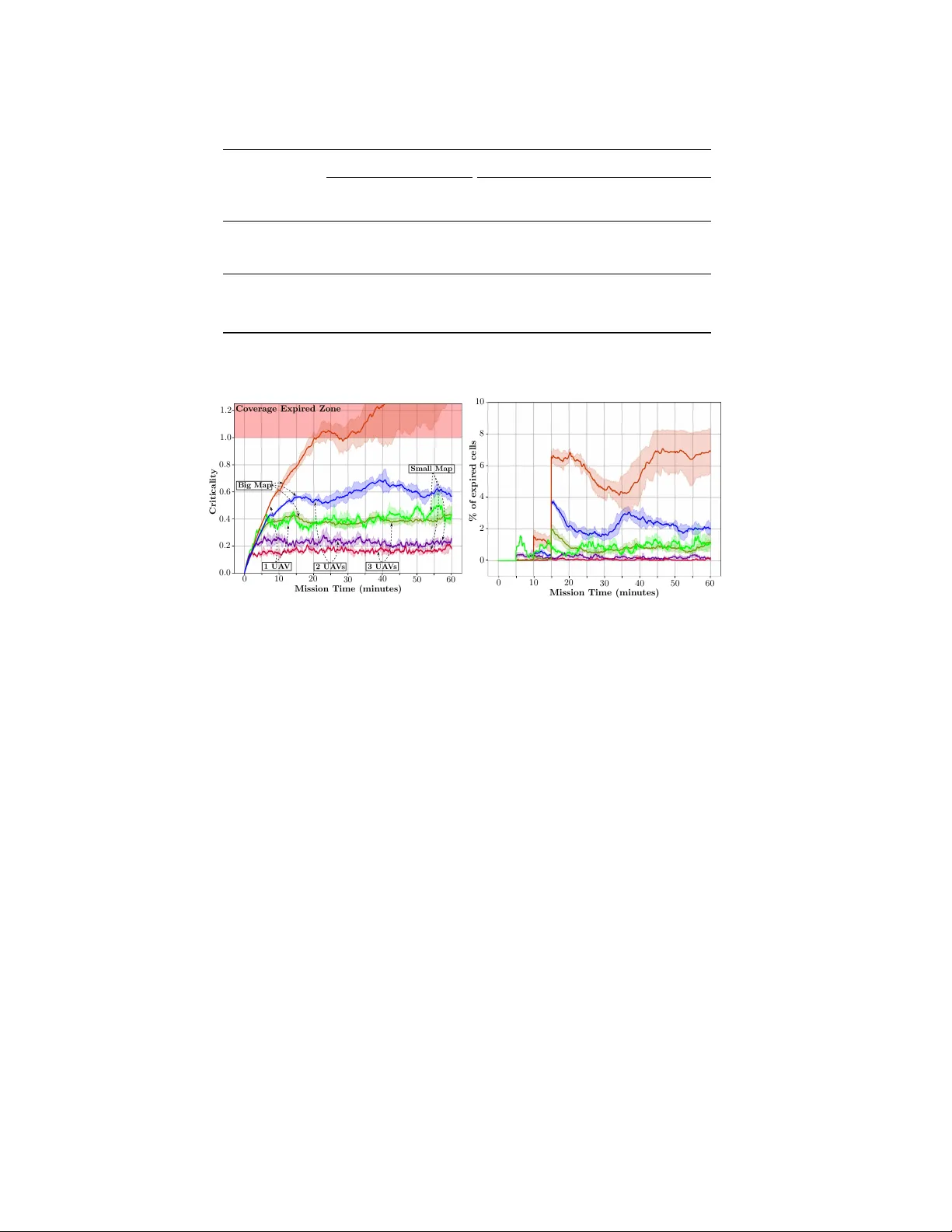
A Planning Framework f or P ersistent, Multi-U A V Cov erage with Global Deconfliction T ushar Kusnur*, Shohin Mukherjee*, Dhruv Mauria Saxena, T omoya Fukami, T akayuki Ko yama, Oren Salzman, and Maxim Likhachev *equal contribution Abstract Planning for multi-robot co verage seeks to determine collision-free paths for a fleet of robots, enabling them to collecti vely observe points of interest in an en- vironment. Persistent cov erage is a variant of traditional coverage where co verage- lev els in the en vironment decay over time. Thus, robots hav e to continuously re visit parts of the en vironment to maintain a desired cov erage-lev el. F acilitating this in the real world demands we tackle numerous subproblems. While there e xist standard solutions to these subproblems, there is no complete framew ork that addresses all of their indi vidual challenges as a whole in a practical setting. W e adapt and com- bine these solutions to present a planning framework for persistent cov erage with multiple unmanned aerial vehicles (U A Vs). Specifically , we run a continuous loop of goal assignment and globally deconflicting, kinodynamic path planning for mul- tiple U A Vs. W e e valuate our frame work in simulation as well as the real world. In particular , we demonstrate that (i) our frame work exhibits graceful coverage—gi ven sufficient resources, we maintain persistent cov erage; if resources are insufficient (e.g., having too fe w U A Vs for a gi ven size of the en viornment), cov erage-levels decay slowly and (ii) planning with global deconfliction in our frame work incurs a negligibly higher price compared to other weaker , more local collision-checking schemes. (V ideo: https://youtu.be/aqDs6Wymp5Q ) 1 Introduction T raditional robot-coverage is the problem of determining a collision-free path for a robot that covers all points of interest in an en vironment [ 10 ]. P ersistent co v- erage seeks to continuously maintain a desired cover age-level ov er an environ- ment [ 9 , 17 , 22 ]. In our case, cov erage-levels degrade o ver time, thereby increasing the urgency with which points must be revisited. For example, consider a floor- cleaning robot—once a part of the floor is cleaned, more dust will e ventually collect ov er it and thereby decrease its co verage-le vel. There has been a rise in the use of T . Kusnur · S. Mukherjee · D. M. Saxena · O. Salzman · M. Likhachev Carnegie Mellon University , Pittsbur gh, P A, USA. e-mail: {tkusnur, shohinm, dsaxena, osalzman, mlikhach}@andrew.cmu.edu T . Fukami · T . Koyama Mitsubishi Heavy Industries, Ltd., T ok yo, Japan. e-mail: {tomoya_fukami, takayuki_ koyama}@mhi.co.jp Acknowledgement : This w ork was sponsored by Mitsubishi Heavy Industries, Ltd. The authors would also like to thank Daniel Feshbach for help with creating figures. 1 2 (a) Prior itized Planning F ramew ork (b) Fig. 1: ( a ) The System Manager ( SM ) communicates with all UA Vs; it sends up-to-date copies of committed plans to corresponding UA Vs and updates them using information receiv ed from the Prioritized Planner ( PP ) ( b ) Prioritized planning frame work: For each UA V , the Goal Assigner ( GA ) selects the ne xt goal using the up-to-date map from the PP and the Goal Planner ( GP ) then plans a feasible path to this goal, which is appended to its committed plan robots to perform tasks cast as persistent-coverage problems, such as environmen- tal monitoring, exploration, inspection, post-disaster assessment, monitoring traf fic congestion ov er a city , etc. [ 18 , 22 , 24 , 27 ]. In general, coverage path-planning is closely related to the intractable covering- salesman pr oblem , where an agent must visit neighborhoods of multiple cities while minimizing travel-distance [ 3 ]. Extending this to multiple robots requires collision av oidance (with both static and dynamic obstacles), which becomes computation- ally expensi ve as the number of robots increase. For persistent coverage, additional algorithmic challenges emer ge since robots need to continuously re visit parts of the en vironment to maintain coverage-le vels. For a single robot tasked with persistent cov erage, there are broadly two decisions to be made: Q1 Where should the robot go next? Q2 Ho w should it get there? W e refer to Q1 and Q2 as goal assignment and goal planning respectiv ely . Addi- tional questions arise when dealing with multiple robots: Q3 Ho w do we plan for multiple robots? Q4 Ho w do we av oid inter-robot collisions? Assuming a centralized planner, we address Q3 by sequential, decoupled planning instead of planning in the joint state-space of all robots for tractability . Specifically , we use prioritized planning [ 8 ]. W e use the notion of committed plans to tie our answers to these questions to- gether . These are defined as parts of plans that robots commit to e xecute, in contrast to the rest of their plans which may be modified after reassessing the en vironment. W e maintain the in variant of global deconfliction —no new committed plan inter- sects any other e xisting committed plan in space or time, thereby answering Q4 . In this paper , we present a planning framework to address all the above questions. A block diagram of the complete frame work is presented in Fig. 1 . T o the best of our A Planning Framew ork for Persistent, Multi-U A V Coverage 3 knowledge, this work is the first to answer all of these questions in unison for real- world, persistent coverage with multiple robots. For our application, these robots are Unmanned Aerial V ehicles (UA Vs). The System Manager ( SM , Sec. 4.1 ) is our communication interf ace between the centralized planner and indi vidual U A Vs. It is responsible for back-and-forth communication of up-to-date information between the two. The Prioritized Planner ( PP , Sec. 4.2 ) is responsible for answering Q3 . Thereafter , the Goal Assigner ( GA , Sec. 4.3 ) answers Q1 and specifies the location the next U A V should fly to. This is fed to the Goal Planner ( GP , Sec. 4.4 ), which plans a kinodynamically feasible path for the UA V to the goal, answering Q2 . Part of this plan is appended to the existing committed plan of the UA V . The PP , which operates continuously in a loop, then begins the next planning cycle, answering Q3 again. W e only append a part of computed plans to committed plans of UA Vs (further detailed in Sec. 4 ). This is done so that we maintain committed plans of a pre- specified maximum duration (denoted by t max ) 1 . There is a trade-off in volved in making t max too short or too long. Sec. 4 provides more insight into how and why this arises. W e rely on globally deconflicting paths for U A Vs since other , more lo- cal collision-checking mechanisms have a higher risk of causing deadlocks 2 . Some other approaches utilise conflict detection and resolution systems to repair conflict- ing paths [ 4 ]. Our approach solv es for deconflicting paths by construction and main- tains the in variant of global deconfliction. In Sec. 2 , we conte xtualize our work among the Orienteering Problem (OP) [ 30 ] and the V ehicle Routing Problem (VRP) [ 29 ], coverage path-planning [ 10 ], and frontier-based exploration [ 31 ]. Sec. 3 formalizes the persistent-cov erage problem we aim to solve and introduces the notion of priorities over coverage zones. Sec. 4 provides details about our planning framework and each of its constituent parts. In Sec. 5 , we present results of the performance of our framework in both simulated and real-world en vironments. Finally , Sec. 6 discusses the consequences of some design-related decisions and proposed extensions. 2 Related W ork A majority of existing literature casts the persistent coverage problem as an instan- tiation of the OP or the VRP . An OP seeks to determine a path for an agent limited by a time- or distance-budget that visits a subset of all surveillance sites in an envi- ronment and maximizes the sum of associated scores collected. An extension of this to multiple agents is kno wn as the T eam Orienteering Problem (T OP) [ 30 ]. There are a number of works that apply solutions of the OP to surv eillance with aerial vehicles over a small number of surveillance sites [ 14 ]. The formulation by Leahy et al. comes closest to our work because of its capability of assigning time windows to each cov erage-zone as temporal logic constraints [ 15 ]. 1 This duration depends on the type and capability of the robots, the number of robots, and the cov erage map. 2 T wo or more robots are in a deadloc k if they are not in collision, but executing any v alid action for any one of the robots w ould cause them to collide with another . Hence, they remain stationary . 4 Giv en a number of agents at a depot and distances among all surveillance sites and the depot, the VRP seeks to find a minimum-distance tour for each agent such that it visits each site at least once. Michael et al. address persistent surveillance with aerial v ehicles as a VRP with modifications to model continuous site visits [ 11 , 25 ]. The OP and VRP are both v ariants of the Tra veling Salesman Problem (TSP) and thus NP-hard. Moreover , in our case, formulating the problem as a TOP or VRP is not enough since our problem also has an element of 2D co verage. One could consider e very discrete part of the en vironment as a surveillance site in a TOP or VRP to enable 2D cov erage, but this is impractical due to increasing computational complexity with the number of surv eillance sites. Smith et al. tackle a very similar problem by assuming pre-planned paths, decou- pling path-planning and speed-control for deconfliction [ 23 ]. Planning paths for 2D cov erage has been extensi vely studied in robotics [ 10 ]. T ypical solutions to static cov erage inv olve environmental partitioning via V oroni tessellations and feedback control laws with local collision-avoidance schemes [ 21 ]. Environmental partition- ing is also a recurring strategy for dynamic and persistent coverage [ 13 ]. Howe ver , such partitioning restricts individual robots to specific parts of the en vironment. For real-world settings, robot path-planners must adhere to kinodynamic motion- constraints. Thakur et al. solve the TOP and path-planning simultaneously to gen- erate 3D ( x , y , θ ) space-parametrized trajectories, but without temporal deconflic- tion [ 28 ]. Many also formulate planning for persistent surveillance as a mixed- integer linear program (MILP) [ 5 ]. Howe ver , such MILP formulations introduce limitations that are typically managed by planning for constant-speed paths [ 1 ]. A vital part of our framework is to ensure UA Vs fly to appropriate goals, so that they simultaneously cover dif ferent parts of the environment. W e adapt frontier- based exploration to assign such goals to UA Vs. Y amauchi et al. first proposed this for single and multiple robots based on an occupancy-grid representation of the en vironment [ 31 ]. Many extensions ha ve been proposed since then, which combine the information gain or expected benefit of the goal and the distance to it, also called next-best-vie w approaches [ 2 ]. Zhu et al. also apply this to e xploration and coverage with micro aerial vehicles (MA Vs) [ 32 ]. W e use frontier-based exploration to trade off between cell-proximity and cell-criticality (defined formally in Sec. 3 ). T o be able to do this online, we use a search-based approach similar to Butzke et al. [ 6 ]. 3 Problem F ormulation Our problem definition is characterized by a mission-map M , and a set of N U A Vs { U 1 , . . . , U N } , tasked with covering the area represented by M . Each U A V U k is a kinodynamically constrained system, with an associated coverage- or sensor- radius r k . Let the cell at row i and column j of M be c i , j . A U A V U k is at cell c i , j if the projection of its reference point onto the x , y plane (denoted by U loc k ) lies in cell c i , j . A cell is said to be covered by a UA V flying over it if any point on the cell is at at most an r k distance from U loc k . This effecti vely assumes a circular sensor-footprint of radius r k centered around U loc k . Each cell c i , j is associated with two temporal properties—its lifetime ( c i , j ) and its age a ( c i , j ) . The age of a cell A Planning Framew ork for Persistent, Multi-U A V Coverage 5 High Prio rit y Medium Priorit y Lo w Priori t y No Co v erage Zone No Fly Z one 5 5 5 5 5 5 5 5 5 5 5 5 5 5 5 5 10 10 10 10 10 10 10 10 10 10 10 10 10 10 10 10 10 10 10 10 10 10 10 10 10 10 10 10 10 10 10 10 10 10 10 10 10 10 10 10 10 10 10 10 10 10 10 10 10 10 5 5 5 5 5 5 5 5 5 15 15 15 15 15 15 15 15 15 15 15 15 15 15 15 15 15 15 15 15 15 15 15 15 15 (v alues in m in utes) Fig. 2: An example of a mission-map M , where each cell is colored according to its lifetime. F or example, a green cell with a lifetime of 15 minutes implies that no more than 15 minutes should pass between two consecuti ve times a U A V covers it. is the time passed since the cell was last co vered by a UA V , while its lifetime is a desired bound on its age (as shown in Fig. 2 ). There are two types of cells in our problem specification: (i) standard cells (that U A Vs need to cover), and (ii) obstacle cells (that UA Vs cannot fly over). Based on this, we define the following maps: 1. Priority Map, M P = c i , j : c i , j is a standard cell ∧ ( c i , j ) < ∞ . In other words, M P is the set of all standard cells that a U A V will need to co ver in finite time since the start of the mission. 2. No-cov erage Map, M NC = c i , j : c i , j is a standard cell ∧ ( c i , j ) = ∞ . In other words, M NC is the set of all standard cells in the mission-map that a UA V can fly ov er , but does not need to cov er . 3. Obstacle Map, M O = c i , j : c i , j is an obstacle cell . The mission-map can then be defined as M = M P ∪ M NC ∪ M O . Fig. 2 contains an example of a mission-map with three dif ferent priority-lev els. Giv en a mission-map and a set of U A Vs, our problem is to compute U A V -plans such that the following properties hold: P1 Feasibility—the motion of each U A V adheres to its kinodynamic constraints. P2 Deconfliction—no two U A Vs collide. In our specific setting, all UA Vs are constrained to fly at the same altitude, so we say that two U A Vs U p and U q collide if they come within some predefined distance d min of each other . P3 Persistence—the age of each cell is smaller or equal to its lifetime. P4 Flexibility—U A Vs can be dynamically added or remov ed to the system. P1 and P2 are hard constraints that must always be satisfied. P3 depends on the mis- sion specification—the number of UA Vs deployed, their capabilities (speed, sensor radii etc.) and the mission-map (size and lifetime of each cell). Our frame work sup- ports P4 without af fecting P1 and P2 , howe ver it will affect (help or hinder) our ability to satisfy P3 . 4 A pproach Our approach, depicted in Fig. 1 , consists of a System Manager ( SM ) which serves as an interface between the centralized planning frame work and indi vidual U A Vs. 6 It maintains the priority map M P by updating locations of individual U A Vs 3 . Every planning cycle, the SM passes the three maps to the Prioritized Planner ( PP ). The PP then iterates ov er all the U A Vs in a round-robin fashion. For each U A V U k , it generates a local copy of M P k that accounts for the committed plans of the other U A Vs. This priority map M P k is used by the Goal Assigner ( GA ) to assign a goal (in terms of x , y location) for the U A V U k . A kinodynamically feasible path to reach this goal is then computed for U k using the Goal Planner ( GP ). A key notion used within our framew ork is that of committed plans , which are collision-free plans each U A V is committed to execute. While the GP might com- pute plans of long durations (if the goal is f ar away or plan execution requires long, feasible maneuvers), only a portion of this plan will be added to the committed plan, such that it is at most t max long in time. The value of t max must be decided based on the mission since the following ef fects introduce a trade-off: 1. Ef fects of a high value for t max : • The longer the committed plans are, the less reacti ve U A Vs are to any map updates including updates by an operator . • The path computed by the GP might take U k through areas coinciding with parts of the committed plans of U j 6 = k before U j 6 = k cov ers them. This results in redundant coverage. The chances of this happening increase as t max increases. 2. Ef fects of a low v alue for t max : • The shorter the committed plan, the lesser the chance of deviating from it during execution due to imperfect controllers. Ho wev er, this increases the chances of U A V U k ex ecuting the committed plan before the next planning cycle ends, leaving the U A V’ s controller with no plan to ex ecute. W e han- dle this by ensuring that the UA V can ex ecute a stopping-maneuver in this situation, but repeated e xecution of stopping-maneuvers is undesirable. • Having short committed plans increases the frequenc y of goal assignment for a UA V . This causes two adverse effects: (i) A U A V may be assigned a new goal that is different from its pre vious one, which would cause it to aban- don trying to reach the previous goal. (ii) Even if the same goal is assigned, it might lead to “plan thrashing”. A U A V’ s complex dynamics may restrict short plans from letting it make significant progress towards a goal if com- plicated maneuvers are required. 4.1 System Manager The System Manager ( SM ) is the communication interface between the centralized planner and the indi vidual U A Vs, shown in Fig. 1 (left): The SM sends the mission- map M to the PP , and it receiv es the updated committed plans from the PP and sends them out to the respectiv e U A Vs. It maintains the priority map M P by: (i) re- 3 Our framework also allo ws for static obstacles and no-co verage zones to change during a mission, but this is be yond the scope of this paper . A Planning Framew ork for Persistent, Multi-U A V Coverage 7 (a) (b) (c) (d) (e) Fig. 3: T wo successive executions of the GA - GP loop (the map M is colored with 50% opacity). ( a ) The solid yellow and blue lines sho w committed plans for both U A Vs. ( b ) A new goal is as- signed to the yellow U A V . ( c ) A path planned is for the yellow U A V (the old committed plan is a dotted line, the ne w committed plan is a solid line, and the discarded part of the ne w plan is a dashed line). ( d ) The same as ( b ) but for the blue U A V . ( e ) The same as ( b ) but for the blue U A V . setting the age of any standard cells that have been covered since the last update to zero, and (ii) incrementing the age of all other standard cells. 4.2 Prioritized Planner The Prioritized Planner ( PP ) is a state-machine that controls our centralized plan- ning framework by continuously executing R U N P L A N N E R from Alg. 1 . During each ex ecution of R U N P L A N N E R , which we call a planning cycle , the PP is responsible for the following tasks: T1 Update its local copy of the committed plans and M P to reflect the most recent information receiv ed from the SM . T2 Determine which U A V will be planned for during this cycle. T3 Perform a ne w goal assginment for the U A V and plan a path to it 4 . T4 Communicate the result of T3 throughout the frame work. T1 is performed in Lines 4 – 6 in Alg. 1 . The PP clips the part of its local copy of committed plans that ha ve been ex ecuted by the U A Vs since the last planning cycle, and accounts for the part yet to be executed by resetting the age of all the cells in M P that will be cov ered by the committed plans to zero. W e do not prioritize any one UA V over the others, which corresponds to the PP selecting U A Vs in a round-robin fashion, thus achieving T2 . While the PP supports a prioritization over U A Vs, in our experience, assigning equal priorities in this way showed satisf actory performance. T3 is achieved through one iteration of the GA - GP loop sho wn in Fig. 1b . For ease of understanding, we show two successi ve executions of this loop in Fig. 3 . Fig. 3b and 3c correspond to Lines 9 and 10 for the yellow U A V . Fig. 3d and 3e correspond to the same lines for the blue U A V . T4 is performed by Lines 11 – 13 . First, we append to a U A V’ s committed plan to bring it up to t max in length. Second, M P is updated to account for this new plan (same as in Line 6 ) by resetting the age of all the cells that will be covered. Finally , the newly committed plan is communicated to the U A V via the SM . 4 T ask T3 is only done if the selected U A V’ s committed plan is shorter than t max . 8 Fig. 4: Multi-goal Dijkstra search for goal assignment finds the least-cost path to a pseudo-goal connected to all potential goal locations for a robot. It considers the cost of reaching a potential goal from the robot’ s location, and the priority of a goal location reflected in the cost of the edge connecting it to the pseudogoal. In the example abo ve, goal G2 is assigned to the robot. Algorithm 1 Prioritized Planner Loop 1: procedure R U N P L A NN E R 2: N ← number of UA Vs 3: while true do 4: Get latest M = M P , M NC , M O and U loc 1: N from SM 5: Update committed plans (local copies) by using U loc 1: N Clip 6: Update M P with committed plans 7: for k ← 1 : N do 8: if committed plan for U k is short then 9: G k ← G E T G O AL M P Goal assignment ( GA ) 10: π k ← G E T P L A N ( M , G k ) Goal planning ( GP ) 11: Update committed plan for U k with π k Append a portion of π k 12: Update M P with committed plan for U k 13: Send committed plan for U k to SM 4.3 Goal Assigner Recall that the Goal Assigner ( GA ) selects a goal for each U A V to fly to. The grid M P k is the local copy of the Priority Map ( M P ) that belongs to U A V U k . Each of the cells in the eight-connected grid that represents M P k is a potential goal for U k . The GA computes a goal-location G k for each U A V , accounting for ho w urgent ev ery cell in M P k is and the location of the U A V U k . T o simultaneously reason about the urgenc y of the goal and its distance from U k , we build a graph by connecting a pseudo-goal to every cell of the grid M P k . The pseudo-goal is an “imaginary” state connected by “imaginary” pseudo-edges to all cells in the grid as shown in Fig. 4 . The cost of these pseudo-edges is proportional to ( ( i , j ) − a ( i , j )) 5 . The costs of the rest of the edges between adjacent cells in the grid are equal to the Euclidean distance between them. T o find an optimal goal G k , we first find an optimal path from U loc k to the pseudo- goal on this graph using Dijkstra’ s search [ 7 ]. The optimal path minimizes the sum 5 W e lower -limit these costs by a constant to ensure they are strictly positiv e. Moreover , since the U A Vs’ sensors cov er multiple cells, the cost of an edge between cell c i , j and the pseudo-goal is the av erage of ( u , v ) − a ( u , v ) for all cells c u , v cov ered when U loc k = c i , j . A Planning Framew ork for Persistent, Multi-U A V Coverage 9 of the costs of the real-edges (which reflects the cost to reach the goal) and the cost of the pseudo-edge (which reflects the priority of the cell that the pseudo-edge connects). The final goal G k for U A V U k is the parent of the pseudo-goal on this optimal path. 4.4 Goal Planner Once a goal is assigned to U k , the GP computes a kinodynamically feasible path to it via search-based planning on a state-lattice [ 16 , 19 ]. The state-space for each U A V includes its two-dimensional pose ( x , y , θ ) , linear velocity v , and time t . Assuming double-integrator dynamics for each U A V , we generate an action-space consisting of feasible motion primitives. These primitiv es use cells of size 1m × 1m. This dis- cretization is independent of the mission-map discretization. W e implicitly construct a graph using the action space during a weighted-A* search to the goal [ 12 , 20 ]. The search prunes away all transitions that correspond to trajectories that either intersect no-fly zones or collide with the committed plans of other vehicles in space or time. W e terminate the search as soon as a state is expanded whose incoming edge (from the predecessor on the found path) cov ers the goal cell (specifically , the trajectory corresponding to this edge contains a point whose distance to the goal cell is less than r k ). W e assign the time taken to ex ecute an action as its edge-cost in the graph. While our aim is to plan for minimum-time paths, it is also desirable for the U A Vs to fly at high speeds whenev er possible and avoid stopping. F or this reason, we incen- tivize actions with increasing velocities, penalize actions with decreasing velocities, and heavily penalize ho vering. 5 Experimental Setup and Results W e ev aluate our framework in both simulation, where we assume perfect state esti- mation and control, and on real U A Vs, which can deviate from their planned paths. The UA Vs can withstand winds of speeds up to 30 m / s. Thus, the effect of wind is negligible under normal conditions. Accounting for lar ge de viations from planned paths requires replanning and is part of future work. Our framework uses an identi- cal set of parameters in both cases. W e generate motion primitiv es with a maximum speed of 6 m / s and a maximum turning rate of 6 ◦ / s. W e av oid adding angular veloc- ity to the state-space by ensuring that these primitives start and end at zero angular velocity . T wo U A Vs are deemed to hav e collided if at any point in time the distance between these 2D locations is less than d min = 10 m. The parameter r k = 15 m de- fines the circular area directly underneath a U A V that is deemed covered for any 2D location of the U A V . W e impose a planning timeout of 4 s on the Goal Plan- ner , which is how long it is given to compute a plan. W e use an Euclidean-distance heuristic in the W eighted-A* search [ 20 ] with an inflation of 5. Fig. 7d and 7e shows the two cov erage-maps used for the experiments presented in this paper . 10 5.1 Evaluation Metrics W e look at timing statistics for Goal Assignment ( t GA ) and Goal Planning ( t GP ), number of state e xpansions, and number of expansions per second 6 . Since we desire continued movement from each UA V , we also look at the amount of time a UA V is stationary on average across the simulation run ( t stopped ). Additionally , we e valuate our framew ork’ s performance with respect to the criticality of a cell, defined for any cell ( i , j ) at timestamp t as C t ( i , j ) = a t ( i , j ) ( i , j ) , where C t : E ( 2 ) → R is a time-varying measure of criticality . C t ( i , j ) starts with a value of zero and as the cell ages over time, C t ( i , j ) starts to increase. Once the age of a cell reaches its lifetime—namely , C t ( i , j ) equals one—we say that the cell has expir ed . If we av erage this v alue across all cells in the map to be covered, we obtain an estimate idea of how well a team of U A Vs is covering the areas the y have been assigned: ¯ C t = 1 | M P | ∑ ( i , j ) ∈ M P C t ( i , j ) (1) Giv en this measure of criticality , ideal beha vior would be to keep the value of ¯ C t constant ov er the course of a mission, a lo wer value being better . 5.2 Simulation Experiments Hardwar e Platform Simulation experiments were performed on a desktop com- puter running Ub untu 16.04 and equipped with an Intel Core i7-4790K processor and 20 GB of RAM. Planner Evaluation W e present simulation results on both maps from Fig. 7 for 10 minutes in T able 1 . W e observe that by increasing the number of U A Vs, Goal As- signment times are not affected, whereas Goal Planning times increase significantly since GP must now compute deconflicting plans for a larger number of U A Vs. De- spite this, the total amount of stationary time spent by a UA V was at most 19 . 90 s in a 10-minute period. Fig. 5 shows a plot of ¯ C t (Eq. ( 5.1 )) ov er time during a 30- minute mission. In all experiments, our framework is able to keep ¯ C t below a v alue of one except where the number of UA Vs was too small giv en the size of the map (experiment with one UA V and map from Fig. 7 ). This, along with the fact that all plots plateau ov er time, implies that cell-expiration is re gulated on average. Global Deconfliction Satisfactory global deconfliction relies on each UA V always having access to committed plans that are long enough. As discussed in Sec. 4 , size of committed plans can significantly affect performance. W e empirically ev aluate the need and effect of global deconfliction by v arying the lengths of committed plans for different collision-checking schemes. These schemes are: 1. Proposed Frame work: Our approach with global deconfliction. 2. No Collision Checking: The GP performs no collision-checking between UA Vs. 3. Current Position (static): The GP considers the other U A Vs’ current positions as static obstacles. 6 These expansions refer to graph-node e xpansions in the W eighted-A* search. A Planning Framew ork for Persistent, Multi-U A V Coverage 11 Map Number of U A Vs Timing (ms) Path Planning t GA t GP t Tot al Number of Expansions Expansions per second t stopped (%) Fig. 7d 1 90 223 323 413 215 0 2 90 796 898 187 226 2 3 91 1326 1430 286 209 2 Fig. 7e 1 92 172 275 28 204 0 2 91 1163 1265 200 188 < 1 3 91 1433 1536 248 185 3 T able 1: Results of simulation e xperiments (v alues rounded down to the closest integer) and t stopped expressed as a percentage of total mission time. 0.0 0.2 0.4 0.6 0.8 1.0 1.2 Mission Time (m in utes) Criticalit y 0 10 20 30 40 50 60 Mission Time (m in utes) % of expired cells 0 10 20 30 40 50 60 0 2 4 6 8 10 Fig. 5: Left: A verage criticality of cells in M P during simulated experiments. Right: Spikes occur at 5, 10, 15 minutes since these are the three different cell lifetimes in the initial M P . Colors are consistent across the two plots. 4. Quarter , Half and Full Plan (static): The GP assumes the first quarter, half and whole of the committed plans of other U A Vs to be static obstacles respecti vely . W e plot the number of collisions between U A Vs in Fig. 6a , the a verage time a U A V is stationary in Fig. 6b , and the time tak en by the Goal Planner in Fig. 6c , all against varying lengths of committed plans. Fig. 6 shows that our deconfliction scheme results in competiti ve planning times and also guarantees collision-free U A V mov e- ment with negligible stoppage. Other collision-checking schemes are either overly conservati ve and compute conv oluted, long-winding paths, or simply fail to avoid collisions. 5.3 Real-W orld Experiments Hardwar e Setup For the real-world experiments, our planning framew ork was run on a Lenov o T470s laptop running Ubuntu 16.04 and equipped with an Intel Core i7-7600U processor and 20 GB of RAM. Planner Evaluation W e present results from real-world experiments in T able 2 . Fig. 8a plots ¯ C t for eight real-world runs. Additionally , dynamic remov al of U A Vs from the mission was tested in fiv e of these runs, and the remaining UA Vs were 12 Num b er of Collisions Bu er Le ngth (s) (a) Bu er Le ngth (s) Time St opp ed (% ) (b) Goal Pl anning Time (s) Bu er Le ngth (s) (c) Fig. 6: Effect of changing the committed plan length for different collision checking mechanisms. Since each curve represents a single mission execution, we do not show confidence intervals. The lines for Full Plan (static) and Our F ramework coincide in (a). (a) (b) (c) (d) (e) Fig. 7: ( a ) UA V used in the experiments. ( b ) The two UA Vs (circled in red) executing a mission. ( c ) GUI showing a satellite image of the mission site along with U A V data overlay . ( d ) Map used for experiments (big; cov erage zone roughly 400m × 400m). ( e ) Map used for experiments (small; cov erage zone roughly 200m × 100m) left undisturbed. Be yond this point, we are only covering the area with one U A V . Hence, it is expected to see criticality increase. By iterativ ely planning and ex ecuting computed paths, we isolate our planner from the stochasticity of controller-based ex ecution in the real world. Our planner quantitati vely performs just as well in the real-world as it does in simulation in spite of this stochasticity . This is because our framew ork seeks latest information about U A V and map statuses from the real world and constantly uses it to repeatedly solv e our myopic version of the full problem (as explained in Sec. 4 ). Map Number of U A Vs Timing (ms) Path Planning t GA t GP t total Number of Expansions Expansions per second t stopped (%) Fig. 7e 1 105 240 363 37 186 0.00 2 117 1181 1325 162 152 7.12 T able 2: Results of real-world experiments averaged over 8 runs (rounded do wn to the nearest integer) and t stopped expressed as a percentage of total mission time (maximum o ver all runs). A Planning Framew ork for Persistent, Multi-U A V Coverage 13 0 100 200 300 400 500 600 Mission Time (s) Criticalit y 0.0 0.2 0.4 0.6 0.8 0.1 0.3 0.5 0.7 700 Big Map 1 UA V (a) 0 100 200 300 400 500 600 Mission Time (s) Criticalit y 0.0 0.2 0.4 0.6 0.8 0.1 0.3 0.5 0.7 (b) Fig. 8: (a) Coverage criticality over time in the real-world: unless explicitly pointed to by arrows, the curves represent an experiment with two UA Vs run on the smaller map. A cross ( × ) on a curve indicates the point in time when one of the two U A Vs was removed from the mission. (b) Comparison of all simulation and real-world missions executed in the small map from Fig. 7e by two U A Vs. The black curve with confidence intervals corresponds to the simulated experiments. 6 Conclusion and Future W ork W e present and ev aluate a planning framew ork for real-world, persistent cov erage with multiple U A Vs. Our framew ork continuously decides where UA Vs should fly and computes kinodynamically feasible, globally deconflicting plans. W e ev aluate our framework in both simulated and real-world settings. W e also motiv ate and com- pare global deconfliction with weaker , more local collision-av oidance schemes. In many practical settings like ours, state spaces are high-dimensional and time for deliberation is limited. Planning times can be a bottleneck in these cases and cause delays. While our stopping maneuvers handle such situations, a natural e xten- sion is to incorporate anytime planning [ 26 ]. In the current framew ork, the goal assignment is based on priorities and is de- coupled from goal planning. This is greedy and not optimal. Better strategies to repeatedly cover pre viously observed coverage-zones can be learned from data and added as macro-actions in the planner . References 1. Ademoye, T .A., Davari, A.: T rajectory planning for multiple autonomous systems using mixed integer linear programming. In: Proceedings of the Thirty-Eighth Southeastern Symposium on System Theory , pp. 175–179. IEEE (2006) 2. Adler , B., Xiao, J., Zhang, J.: Autonomous e xploration of urban environments using unmanned aerial vehicles. Journal of Field Robotics 31 (6), 912–939 (2014) 3. Arkin, E.M., Hassin, R.: Approximation algorithms for the geometric co vering salesman prob- lem. Discrete Applied Mathematics 55 (3), 197–218 (1994) 4. Barnier , N., Allignol, C.: Trajectory deconfliction with constraint programming. The Knowl- edge Engineering Revie w 27 (3), 291–307 (2012) 5. Bellingham, J.S.: Coordination and control of U A V fleets using mixed-integer linear program- ming. Ph.D. thesis, Massachusetts Institute of T echnology (2002) 6. Butzke, J., Likhachev , M.: Planning for multi-robot exploration with multiple objecti ve utility functions. In: IROS, pp. 3254–3259 (2011) 7. Dijkstra, E.W .: A note on two problems in connexion with graphs. Numerische mathematik 1 (1), 269–271 (1959) 14 8. Erdmann, M., Lozano-Perez, T .: On multiple moving objects. Algorithmica 2 (1-4), 477 (1987) 9. Franco, C., L ´ opez-Nicol ´ as, G., Sag ¨ u ´ es, C., Llorente, S.: Persistent co verage control with v ari- able cov erage action in multi-robot en vironment. In: CDC, pp. 6055–6060 (2013) 10. Galceran, E., Carreras, M.: A survey on coverage path planning for robotics. Robotics and Autonomous Systems 61 (12), 1258–1276 (2013) 11. Golden, B.L., Raghavan, S., W asil, E.A.: The vehicle routing problem: latest advances and new challenges, v ol. 43. Springer Science & Business Media (2008) 12. Hart, P .E., Nilsson, N.J., Raphael, B.: A formal basis for the heuristic determination of min- imum cost paths. IEEE T ransactions on Systems Science and Cybernetics 4 (2), 100–107 (1968) 13. Kapoutsis, A.C., Chatzichristofis, S.A., Kosmatopoulos, E.B.: D ARP: divide areas algorithm for optimal multi-robot cov erage path planning. Journal of Intelligent & Robotic Systems 86 (3-4), 663–680 (2017) 14. Keller , J.F .: Path planning for persistent surv eillance applications using fix ed-wing unmanned aerial vehicles. Computers & Operations Research (2016) 15. Leahy , K., Zhou, D., V asile, C.I., Oikonomopoulos, K., Schwager, M., Belta, C.: Persistent surveillance for unmanned aerial vehicles subject to charging and temporal logic constraints. Auton. Robots 40 (8), 1363–1378 (2016) 16. Likhachev , M., Ferguson, D.: Planning long dynamically feasible maneuvers for autonomous vehicles. IJRR 28 (8), 933–945 (2009) 17. Mellone, A., Franzini, G., Pollini, L., Innocenti, M.: Persistent coverage control for teams of heterogeneous agents. In: CDC, pp. 2114–2119 (2018) 18. Nedjati, A., Izbirak, G., V izvari, B., Arkat, J.: Complete coverage path planning for a multi- U A V response system in post-earthquake assessment. Robotics 5 (4), 26 (2016) 19. Pivtoraik o, M., Kelly , A.: Generating near minimal spanning control sets for constrained mo- tion planning in discrete state spaces. In: IROS, pp. 3231–3237 (2005) 20. Pohl, I.: Heuristic search vie wed as path finding in a graph. Artificial intelligence 1 (3-4), 193–204 (1970) 21. Schwager , M., Rus, D., Slotine, J.J.: Decentralized, adaptiv e coverage control for networked robots. IJRR 28 (3), 357–375 (2009) 22. Smith, R.N., Schwager , M., Smith, S.L., Jones, B.H., Rus, D., Sukhatme, G.S.: Persistent ocean monitoring with underwater gliders: Adapting sampling resolution. JFR 28 (5), 714– 741 (2011) 23. Smith, S.L., Schwager , M., Rus, D.: Persistent robotic tasks: Monitoring and sweeping in changing en vironments. arXi v preprint arXiv:1102.0603 (2011) 24. Sriniv asan, S., Latchman, H., Shea, J., W ong, T ., McNair, J.: Airborne traf fic surveillance systems: video surveillance of highway traf fic. In: Proceedings of the A CM 2nd international workshop on V ideo surveillance & sensor networks, pp. 131–135 (2004) 25. Stump, E., Michael, N.: Multi-robot persistent surveillance planning as a vehicle routing prob- lem. In: IEEE International Conference on Automation Science and Engineering, pp. 569–575 (2011) 26. Sun, X., Koenig, S., Y eoh, W .: Generalized adaptive A*. In: AAMAS, pp. 469–476. Interna- tional Foundation for Autonomous Agents and Multiagent Systems (2008) 27. T eixeira, L., Alzugaray , I., Chli, M.: Autonomous aerial inspection using visual-inertial rob ust localization and mapping. In: FSR, pp. 191–204. Springer (2018) 28. Thakur , D., Likhache v , M., Keller , J., Kumar, V ., Dobrokhodov , V ., Jones, K., W urz, J., Kaminer , I.: Planning for opportunistic surv eillance with multiple robots. In: IR OS, pp. 5750– 5757 (2013) 29. T oth, P ., V igo, D.: The vehicle routing problem. SIAM (2002) 30. V ansteenwegen, P ., Souffriau, W ., V an Oudheusden, D.: The orienteering problem: A surve y . European Journal of Operational Research 209 (1), 1–10 (2011) 31. Y amauchi, B., et al.: Frontier -based exploration using multiple robots. In: Agents, v ol. 98, pp. 47–53 (1998) 32. Zhu, C., Ding, R., Lin, M., W u, Y .: A 3D frontier-based exploration tool for MA Vs. In: ICT AI, pp. 348–352 (2015)
Original Paper
Loading high-quality paper...
Comments & Academic Discussion
Loading comments...
Leave a Comment