Resilient Continuum Deformation Coordination
This paper applies the principles of continuum mechanics to safely and resiliently coordinate a multi-agent team. A hybrid automation with two operation modes, Homogeneous Deformation Mode (HDM) and Containment Exclusion Mode (CEM), are developed to …
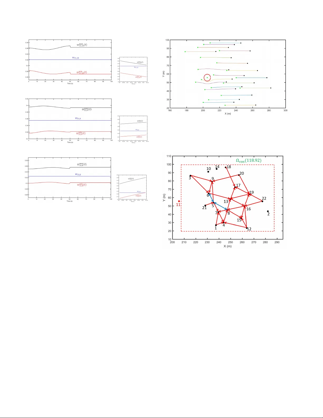
Authors: Hossein Rastgoftar, Ella Atkins
Resilien t Con tin uum Deformation Co ordination ? Hossein Rastgoftar a Ella A tkins b a Dep artment of A er osp ac e Engine ering, University of Michigan, Ann A rbor, MI, 48109 USA b Dep artment of A er osp ac e Engine ering, University of Michigan, Ann A rbor, MI, 48109 USA Abstract This pap er applies the principles of con tin uum mechanics to safely and resiliently coordinate a multi-agen t team. A hybrid automation with t wo op eration mo des, Homogeneous Deformation Mo de (HDM) and Containmen t Exclusion Mode (CEM), are dev elop ed to robustly manage group co ordination in the presence of unpredicted agent failures. HDM b ecomes active when all agents are health y , where the group coordination is defined by homogeneous transformation co ordination functions. By classifying agen ts as leaders and follow ers, a desired n -D homogeneous transformation is uniquely related to the desired tra jectories of n + 1 leaders and acquired b y the remaining follo wers in real-time through local comm unication. The paper offers a no vel approach for leader selection as well as naturally establishing and reestablishing in ter-agent communication whenever the agent team enters the HDM. CEM is activ ated when at least one agen t fails to admit group coordination. This pap er applies unique features of decen tralized homogeneous transformation coordination to quickly detect eac h arising anomalous situation and excludes failed agen t(s) from group co ordination of healthy agents. In CEM, agen t coordination is treated as an ideal fluid flow where the desired agen ts’ paths are defined along stream lines inspired b y fluid flow field theory to circumv ent exclusion spaces surrounding failed agent(s). Key wor ds: Resilien t Multi-agent Co ordination, Physics-based Methods, Lo cal Communication, Con tinuum Deformation, and Decentralized Control. 1 In tro duction Con trol of m ulti-agen t systems has b een widely inv es- tigated o v er the past tw o decades. F ormation and co- op erativ e control can reduce cost and improv e the ro- bustness and capability of reconfiguration in a co op era- tiv e mission. Therefore, researchers hav e b een motiv ated to explore div erse applications for the multi-agen t co or- dination suc h as formation control [32], traffic conges- tion control [30], distributed sensing, [12], co op erative surv eillance [31], and coop erativ e payload transport [18]. 1.1 R elate d Work Cen tralized and decen tralized co op erative control ap- proac hes ha ve been previously prop osed for m ulti-agent co ordination. The virtual structure [25] [24] mo del treats agen ts as particles of a rigid bo dy . Assuming the virtual b o dy has an arbitrary translation and rigid b o dy rota- tion in a 3-D motion space, the desired tra jectory of ev- ? Authors are with the Departmen t of Aerospace Engineer- ing, Universit y of Michigan, Ann Arbor, MI, 48109 USA e- mail: hosseinr@umic h.edu. ery agen t is determined in a cen tralized fashion. Consen- sus [5] [14] [7] [3] [19] [1] [36] [15] [28] [34] and con tain- men t control are the most common decentralized co ordi- nation approaches. Multi-agen t coordination using first- order consensus [16] and second-order consensus [5] [14] has b een extensively inv estigated by researc hers in the past. Leader-based and leaderless consensus ha ve b een studied in Refs. [7] and [3]. Stability of the retarded consensus method was studies in Refs. [19] [1]. Finite- time m ulti-agent consensus of contin uous time systems is studied in Refs. [36] [15]. Refs. [28] [34] ev aluate con- sensus under a switching communication top ology in the presence of disturbances. More recen tly , researchers ha ve inv estigated the resilient consensus problem and provided guarantee conditions for reac hing consensus in the presence of malicious agen ts [4, 9, 10, 26]. W eigh ted Mean Subsequence Re- duced (W-MSR) is commonly used to detect an adv er- sary and remov e malicious agent(s) from the communi- cation net w ork of normal agen ts [4, 10]. r -robustness and ( r , s ) -robustness conditions are used to prov e netw ork resilience under consensus. Particularly , ( f + 1 , f + 1 ) - robustness is considered as the necessary and sufficient condition for resilience of the consensus protocol in the Preprin t submitted to Septem b er 24, 2019 presence of f malicious agents [4]. Con tainmen t con trol is a decen tralized leader-follow er approac h in whic h multi-agen t co ordination is guided b y a finite n um b er of leaders and acquired by follow ers through lo cal comm unication. Necessary and sufficient conditions for the stability of contin uum deformation co- ordination hav e b een pro vided in Refs. [17]. Ref. [6] stud- ies the con vergence of con tainment control and demon- strates that follow ers ultimately conv erge to the conv ex h ull defined by leaders. Containmen t con trol under fixed and switc hing communication protocols are studied in Refs. [2] and [11], respectively . Refs. [29, 35] study finite- time con tainment stability and con vergence. Contain- men t con trol stabilit y in the presence of comm unication dela y is studied in Refs. [27, 33]. Con tin uum deformation for large-scale coordination of m ulti-agen t systems is developed in [20]. Similar to con tainment con trol, contin uum deformation is a leader-follo w er approac h in which a group coordination is guided b y a finite num b er of leaders and acquired b y follow ers through lo cal communication [22]. Because con tin uum deformation defines a non-singular mapping b et w een reference and current agent configurations at an y time t , follo wer communication w eigh ts are con- sisten t with leader agents’ reference p ositions in the con tin uum deformation co ordination. The contin uum deformation metho d adv ances containmen t control by formal characterization of safet y in a large-scale co ordi- nation. Assuming contin uum deformation is given by a homogeneous transformation, in ter-agen t collision and agen t follow er containmen t are guaran teed in a con- tin uum deformation coordination by assigning a lo wer limit on the eigen v alues of the Jacobian matrix of the homogeneous transformation. Therefore, a large num- b er of agen ts participating in a contin uum deformation co ordination can safely and aggressively deform to pass through narrow passages in a cluttered environmen t. 1.2 Contributions and Outline This pap er prop oses a physics-inspired approach to the resilien t m ulti-agent co ordination problem. In particu- lar, multi-agen t coordination is mo deled b y a h ybrid au- tomation with tw o ph ysics-based co ordination modes: (i) Homogeneous Deformation Mo de (HDM) and (ii) Con- tainmen t Exclusion Mo de (CEM). HDM is activ e when all agen ts are healthy and can ad- mit the desired co ordination defined by a homogeneous deformation. In the HDM, agen ts are treated as parti- cles of an n -D deformable b o dy and the desired co ordi- nation, defined based on the tra jectories of n + 1 leaders forming an n -D simplex at any time t , is acquired b y the follo w ers through local communication. 1 . 1 This paper considers agents as particles of 2-D and 3-D CEM is activ ated once an adv ersarial situation is de- tected due to unpredicted v ehicle or agen t failure. The pap er offers a no vel approach for rapid detection of each anomalous or failed agent and excludes it from group co ordination with the healthy vehicles. In CEM the de- sired coordination is treated as an irrotational fluid flow and adversarial agents are excluded from the safe plan- ning space by com bining ideal fluid flow patterns in a computationally-efficien t manner. Compared to the existing literature and the authors’ pre- vious work, this pap er offers the following con tributions: (1) The pap er offers a nov el distributed approac h for detection of anomalous situations in which unex- p ected vehicle failure(s) disrupt collective vehicle motion. (2) This pap er adv ances the existing contin uum defor- mation co ordination theory by relaxing the follow er con tainmen t constrain t and offering a tetrahedral- ization approach to assign follow ers’ communica- tion weigh ts in an unsup ervised fashion. (3) The paper prop oses a mo del-free guaran tee condi- tion for conv ergence and inter-agen t collision av oid- ance in a large-scale homogeneous transformation. (4) Compared to existing resilient co ordination work [9] [26] [4] [10], this pap er offers a computationally- efficien t safety recov ery metho d. At CEM, ev ery agen t assigns its own desired tra jectory without comm unication with other agents only by kno wing the geometry of the unsafe domains enclosing the anomalous agen ts, as w ell as its own reference p o- sition when the CEM is activ ated. (5) This pap er prop oses a tetrahedralization method to (i) naturally establish/reestablish in ter-agent com- m unication links and w eigh ts, (ii) classify agents as b oundary and follo wer agen ts, (iii) determine lead- ers in an unsup ervised fashion. (6) The authors b eliev e this is the first pap er describing safe exclusion of a failed agen t in a co op erative team with inspiration from fluid flo w mo dels. This pap er is organized as follows. Preliminaries in Sec- tion 2 are follo wed by a resilient contin uum deformation form ulation in Section 3. Physics-based models for the HDM and CEM are described in Section 4. Op eration of the resilient con tinuum deformation coordination is mo deled by a hybrid automation in Section 5. Simula- tion results presen ted in Section 6 are follow ed b y con- cluding remarks in Section 7. deformable b o dies where 2-D and 3-D homogeneous defor- mation defines the desired coordination at the HDM. There- fore, n is either 2 or 3. 2 2 Preliminaries 2.1 Position Notations The follo wing p osition notations are used throughout this pap er: Reference p osition of vehicle i is denoted b y r i , 0 = x i , 0 y i , 0 z i , 0 T . In this p ap er, a r efer enc e c onfigur ation is define d b ase d on agents’ curr ent p o- sitions onc e they enter the HDM. Actual p osition of v ehicle i is denoted r i ( t ) = [ x i ( t ) y i ( t ) z i ( t )] T at time t . Lo cal desired p osition of v ehicle i is denoted b y r i , d ( t ) = [ x i , d ( t ) y i , d ( t ) z i , d ( t )] T at time t . r i , d is up- dated through lo cal communication and defined based on actual p ositions of the in-neigh b or vehicles of agen t i . Global desired position of vehicle i is denoted by r i , c ( t ) = [ x i , c ( t ) y i , c ( t ) z i , c ( t )] T at time t . The transient error is defined as the difference betw een actual p osition r i ( t ) and global desired position r i , c ( t ) for vehicle i at an y time t . 2.2 Motion Sp ac e T etr ahe dr alization and Λ Op er ator Assume c ∈ R 3 × 1 ; p 1 , p 2 , · · · , p n + 1 ∈ R 3 × 1 are n + 1 arbitrary p osition vectors in a 3-D motion space. Then, rank op erator < n is defined as follows: n = 2 , 3 , < n ( p 1 , · · · , p n ) = rank h p 2 − p 1 · · · p n + 1 − p 1 i . (1) If p 1 , · · · , p n + 1 are positioned at the v ertices an n -D simplex, then < n ( p 1 , · · · , p n ) = n . p 1 , p 2 , p 3 , and p 4 form a tetrahedron for n = 3, if < 3 ( p 1 , p 2 , p 3 , p 4 ) = 3. p 1 , p 2 , and p 3 form a triangle for n = 2, if < 2 ( p 1 , p 2 , p 3 ) = 2. Op erator Λ ( n = 2 , 3 ): Assume p 1 , p 2 , p 3 , and p n 4 are kno wn p oints in a 3-D motion space, where < 3 p 1 , p 2 , p 3 , p n 4 = 3 . (2) Then, op erator Λ can b e defined as follows: n = 2 , 3 , Λ p 1 , p 2 , p 3 , p n 4 , c n = " p 1 p 2 p 3 p 4 n 1 1 1 1 # − 1 " c n 1 # , (3) where c n is the p osition of a p oint in a 3-D motion space. If < 3 p 1 , p 2 , p 3 , p n 4 = 3, Λ ( p 1 , · · · , p n , c n ) exists and has the following prop erties [23]: (1) The sum of the entries of Λ is 1 for an y configuration of vectors p 1 , · · · , p n 4 and c n for n = 2 , 3. (2) If Λ > 0 , c n is inside the tetrahedron formed by p 1 , · · · , p n 4 . Otherwise, it is outside the tetrahedron. Motion Space T etrahedralization : A 3-D motion space can b e divided into tw o subspaces that are inside Figure 1. Graphical representation of the virtual agent p 2 4 . and outside of the tetrahedron defined by vectors p 1 , p 2 , p 3 , and p n 4 , if < 3 p 1 , p 2 , p 3 , p n 4 = 3. F or n = 3 , p 1 , p 2 , p 3 , p 4 , and c represent real p oints (agen ts) in a 3-D motion space, if < 3 ( p 1 , p 2 , p 3 , p 4 ) = 3. Therefore, p 3 4 = p 4 and c 3 = c . F or n = 2 , p 1 , p 2 , and p 3 are the real p oints forming a triangle in a 3-D motion space. Given p 1 , p 2 , and p 3 , virtual point p 2 4 = p 1 + Ξ ( p 3 − p 1 ) × ( p 2 − p 1 ) , (4) where Ξ , 0 is constan t. Note that p 2 4 , defined by Eq. (4), is p erp endicular to the triangular plane made b y agen ts p 1 , p 2 , and p 3 (see Fig. 1). Consequen tly , virtual agen t p 2 4 and in-neighbor agent p 1 , p 2 , and p 3 form a tetrahedron. The pro jection of c on the triangular plane made by p 1 , p 2 , and p 3 is denoted b y ˜ c 2 and expressed as follows: c 2 = c − ( c · n 1 − 4 ( p 1 , p 2 , p 3 )) n 1 − 4 ( p 1 , p 2 , p 3 ) , (5) where unit vector n 1 − 4 ( p 1 , p 2 , p 3 ) = ( p 3 − p 1 ) × ( p 2 − p 1 ) k ( p 3 − p 1 ) × ( p 2 − p 1 ) k (6) is normal to the triangular plane made by p 1 , p 2 , and p 3 . Prop osition 1. L et Λ b e expr esse d in c omp onent-wise form: Λ = h λ 1 λ 2 λ 3 λ 4 i T . If n = 2 , λ 4 p 1 , p 2 , p 3 , p 2 4 , c 2 = 0 for any arbitr ary p osi- tion c 2 . Pr o of. Given p 1 , p 2 , p 3 , and p n 4 , λ 4 p 1 , p 2 , p 3 , p n 4 , c n is obtained as follows: λ 4 p 1 , p 2 , p 3 , p n 4 , c n = k c n − c 2 k k p n 4 − p 1 k . (7) 3 F or n = 2, the denominator of Eq. (7) is 0, th us λ 4 p 1 , p 2 , p 3 , p n 4 , c n = 0 for an y arbitrary p osition of p oin t c in the motion space. Op erator Λ will b e used to (i) determine b oundary and in terior agents, (ii) sp ecify follo w ers’ in-neigh b or agen ts, (iii) assign follow ers’ communication weigh ts in a 2-D and 3-D homogeneous deformation co ordination, and (iv) detect anomalies in a group co ordination. 2.3 Homo gene ous Deformation A homogeneous deformation is an affine transforma- tion 2 giv en by r i , c ( t ) = Q ( t ) r i , 0 + d ( t ) , (8) where Q ( t ) is the Jacobian matrix, d ( t ) is the rigid-bo dy displacemen t v ector, r i , 0 is the reference p osition of agen t i ∈ V H ( t ) , and V H ( t ) defines index num b ers of healthy agen ts at time t . α p ar ameters : Let V H ( t ) b e expressed as V H = V L Ø V F . (9) where V L = { i 1 , · · · , i n + 1 } and V F ( t ) = { i n + 2 , · · · , i N F } are disjoint sets defining leaders and follo wers at time t . Let r i 1 , 0 , · · · , r i n + 1 , 0 denote the reference p ositions of the leaders and r i j , 0 denotes the reference p osition of follo w er i j ∈ V , where reference positions are all assigned at the time agents first enter HDM. Then, w e can define α parameters α i j , i 1 through α i j , i 4 as follows: h α i j , i 1 · · · α i j , i 4 i T = Λ r i 1 , 0 , r i 2 , 0 , r i 3 , 0 , r n i 4 , 0 , r n i j , 0 , (10) where r n i 4 , 0 = r i 4 , 0 n = 3 r i 1 , 0 + Ξ r i 3 , 0 − r i 1 , 0 × r i 2 , 0 − p i 1 , 0 n = 2 , (11a) r n i j , 0 = ( r i j , 0 n = 3 r i j , 0 − r i j , 0 · n 1 − 4 n 1 − 4 n = 2 , (11b) and n 1 − 4 = n 1 − 4 r i 1 , 0 , r i 2 , 0 , r i 3 , 0 w as previously defined in (6). Note that α i 1 , i 4 = 0, if n = 2 (See Prop osition 1). Glob al Desir e d Position: Because homogeneous defor- mation is a linear transformation, global desired p osition of vehicle i j can b e either given by Eq. (8) or expressed 2 The affine transformation (8) is called Homo gene ous De- formation in contin uum mec hanics [8]. as a con v ex combination of the leaders’ p ositions at an y time t . j ∈ V F , r j , c = n + 1 Õ k = 1 α j , i k r i k , c ( t ) . (12) 3 Problem F orm ulation and Statemen t Consider a 3-D motion space containing M agen ts where ev ery agent is uniquely identified by a n umber i ∈ M = { 1 , · · · , M } . It is assumed that N ( t ) (out of M ) agen ts are enclosed by a rigid-size c ontainment domain Ω con = Ω con ( r , r con ( t )) ⊂ R 3 , (13) at time t . Let r con ( t ) ∈ R 3 × 1 b e the nominal position of the containmen t domain given by r con ( t ) = N ( t ) Õ i = 1 β i r i , c ( t ) . (14) Note that 0 ≤ β i < 1 is a scaling factor, Í N ( t ) i = 1 β i = 1, and the size of Ω con = Ω con ( r , r con ( t )) ⊂ R 3 do es not c hange o v er time. Identification n umbers of the agents enclosed b y Ω cont ( t ) are defined by set V ( t ) = i ∈ M r i , c ( t ) ∈ Ω con ( r , r con ( t )) (15) Agen ts enclosed by the con tainment region Ω con ( r , r con ( t )) can b e classified as he althy or anomalous agents, where he althy agents admit the group desired co ordination while anomalous agents do not. He althy and anoma- lous vehicles are defined by disjoint sets V H and V A , resp ectiv ely , where V can b e expressed as V = V H Ø V A , (16) where V H = i 1 , · · · , i N F and V A = { i N F + 1 , · · · , i N } . This paper treats agents as particles of a deformable b o dy where the desired tra jectory of vehicle j ∈ V is giv en by Û r j , c x j , c , y j , c , z j , c , t = H j ,γ x j , c , y j , c , z j , c Û q γ ( t ) , (17) where γ is a discrete v ariable defined b y finite set Γ = { CEM , HDM } . Set Γ sp ecifies the collective motion op er- ation mo de. r j , c ( t ) = [ x j , c ( t ) y j , c ( t ) z j , c ( t )] T is the global desired tra jectory of vehicle j , q = q 1 ,γ · · · q γ m ,γ ( t ) T , q 1 ,γ ( t ) through q N , γ ( t ) are the gener alize d c o or dinates sp ecifying the temp oral behavior of the group coordina- tion. F urthermore, j ∈ V , γ ∈ Γ , H j ,γ = h h j , 1 , γ · · · h j , m ,γ i ∈ R 3 × m 4 is the spatially-v arying shap e matrix . h j , 1 , γ ( x j , c , y j , c , z j , c ) ∈ R 3 × 1 through h j , m ,γ ( x j , c , y j , c , z j , c ) ∈ R 3 × 1 are the shap e functions . HDM ( γ = HDM) is activ e when V A = ∅ . Therefore, N F ( t ) = N ( t ) agen ts defined b y set V H are all healthy . The HDM shap e matrix H j , HDM is time-inv arian t (con- stan t), where j ∈ V H . The HDM generalized co ordinate v ector q HDM ∈ R 3 ( n + 1 ) × 1 sp ecifies desired velocity com- p onen ts of all leaders guiding the group contin uum defor- mation coordination. This pap er dev elops a decen tral- ized leader-follo w er approach using the tetrahdralization presen ted in Section 2.2. By classifying agents as lead- ers and follo wers, V H = V L Ð V F (See Eq. (9)). Lead- ers, defined by V L = { i 1 , · · · , i n + 1 } , mov e indep endently . F ollow ers, defined b y V F = { i n + 2 , · · · , i N } , acquire the desired co ordination through lo cal communication with leaders and other follo wers. The paper offers a tetrahe- dralization metho d to determine leaders and follow ers and define inter-agen t communication among vehicles in an unsupervised fashion for an arbitrary reference con- figuration of agents. CEM ( γ = CEM) is activ ated once at least one anoma- lous agen t is detected in which case V A , ∅ . The CEM shap e matrix H j , CEM ( j ∈ V H ) is spatially v arying. In particular, the desired vehicle co ordination of healthy v ehicle j ∈ V H is defined b y an ideal fluid flo w. F or CEM, it is desired that (i) vehicle j ∈ V H mo v es along the surface z j , c = z j x j , c , y j , c , t and (ii) x and y comp o- nen ts of the agen t coordination are defined by an irrota- tional flow. Mathematically sp eaking, w e define coordi- nate transformation φ j , c = φ x j , c , y j , c , t ψ j , c = ψ x j , c , y j , c , t z j , c = z j x j , c , y j , c , t , (18) where j ∈ V H , φ ( x j , c , y j , c , t ) and ψ ( x j , c , y j , c , t ) satisfy the Laplace equation: ∂ 2 φ x j , c , y j , c , t ∂ x 2 j , c + ∂ 2 φ x j , c , y j , c , t ∂ y 2 j , c = 0 (19a) ∂ 2 ψ x j , c , y j , c , t ∂ x 2 j , c + ∂ 2 ψ x j , c , y j , c , t ∂ y 2 j , c = 0 . (19b) F or smo oth ”flo w” every agent j ∈ V H slides along the j -th streamline defined b y j ∈ V H , ψ x j , c , y j , c , t = ψ j , 0 = constant at an y time t . This condition requires that the desired tra jectory of vehicle j ∈ V H satisfy the follo wing equation at any time t : ∂ ψ ( x j , c , y j , c , t ) ∂ x j , c d x j , c d t + ∂ ψ ( x j , c , y j , c , t ) ∂ y j , c d y j , c d t = 0 . (20) Notice that stream and p otential functions satisfy the Cauc h y-Riemann condition. Therefore, the lev el curv es φ ( x , y , t ) = constan t and ψ ( x , y , t ) = constan t are p er- p endicular at the in tersection p oin t. This pap er defines φ ( x , y , t ) and ψ ( x , y , t ) by combining ideal fluid flo w pat- terns so that an obstacle-free motion space is excluded from adversaries. This com bination can split the x − y plane into a safe region defined by set S and unsafe re- gion defined by set U . A one-to-one mapping exists b e- t w een ( x j , y j ) and ( φ ( x j , y j ) , ψ ( x j , y j )) at every p oint in the safe set S . Thus, the Jacobian matrix ( x , y ) ∈ S , j ∈ V H J ( x j , y j ) = ∂ φ ∂ x j ∂ φ ∂ y j ∂ ψ ∂ x j ∂ ψ ∂ y j (21) is nonsigular. P otential and stream fields are generated b y combining “Uniform” and “Doublet” flow patterns. As a result, a single failed vehicle can be separated by a cylinder from the safe region S in the motion space. This pap er also offers a nov el distributed anomaly detec- tion approach by using the prop erties of leader-follow er homogeneous transformation co ordination. Particularly , the Λ op erator is used to c haracterize agen t deviation of agen ts from the desired co ordination to quickly iden tify failed agent(s) that are not admitting the desired con- tin uum deformation. 4 Ph ysics-based Mo deling of HDM and CEM HDM and CEM are mathematically mo deled in this sec- tion. A decen tralized leader follo w er metho d for HDM is dev elop ed in Section 4.1 to acquire a desired con tinuum deformation in an unsup ervised fashion. CEM co ordina- tion is mo deled in Section 4.2. 4.1 Homo gene ous Deformation Mo de (HDM) In HDM, v ehicles are healthy and co op erative. There- fore, | V A | = 0 ( N F = N and V H = V ). Set V H can b e expressed as V H = V L Ð V F , where V L = { i 1 , · · · , i n + 1 } and V F = { i n + 2 , · · · , i N } define leaders and follo wers, re- sp ectiv ely . 4.1.1 Desir e d Homo gene ous Deformation Definition A desired homogeneous transformation can be defined b y m = 3 ( n + 1 ) generalized co ordinates q 1 , HDM , · · · , q 3 ( n + 1 ) , HDM using relation (17), where q HDM ( t ) = q 1 , HDM ( t ) . . . q 3 ( n + 1 ) , HDM ( t ) = v ec © « x i 1 , c · · · x i n + 1 , c y i 1 , c · · · y i n + 1 , c z i 1 , c · · · z i m + 1 , c T ª ® ® ® ® ¬ , (22a) 5 H i j , HDM = h h j , 1 · · · h j , 3 ( n + 1 ) i = I 3 ⊗ h α j , i 1 · · · α j , i n + 1 i , (22b) and j ∈ V . Note that vec (·) is the matrix vectoriza- tion operator. In Section 2.3, it w as describ ed ho w α pa- rameters α j , i 1 through α j , i n + 1 are assigned based on the agen ts’ reference p ositions. 4.1.2 Unsup ervise d A c quisition of a Homo gene ous De- formation Using T etr ahe dr alization A desired homogeneous deformation, defined by n + 1 leaders in an n -D homogeneous deformation, is acquired b y follow ers through lo cal comm unication. Comm unica- tion among health y agen ts is defined by coordination graph G c ( V , E ) with no des V ( V = V H ) and edges E ⊂ V × V . In-neighbor agents of agen t i ∈ V are de- fined by i ∈ V , N i = { j ( j , i ) ∈ E } . Assuming the reference formation of agents is known, n + 1 b oundary agents are selected as leaders. F urther- more, ev ery follo wer i ∈ V F comm unicates with n + 1 in- neigh b or agents where the in-neigh b or agen ts are placed at the vertices of an n -simplex containing follow er i . Figure 2. Example reference formation used for collective motion simulation. A red arrow shows a unidirectional link to a follo wer from its in-neigh b or agen t. Blue arrows sho w bidirectional comm unication. 4.1.3 Classific ation of A gents as L e aders and F ol lowers The no de set V can b e expressed as V = V B Ð V I where V B = { i 1 , · · · , i m B } and V I = { i m B + 1 , · · · , i N } de- fine b oundary and in terior agents, resp ectively . Given agen ts’ reference p ositions, the following true statements are used to assign agen t i ∈ V either as a leader or a follo w er: (1) An n -D homogeneous deformation is defined by n + 1 leaders [20, 21]. Assuming leaders are selected from the b oundary agen ts, V L ⊂ V B . (2) Non-leader boundary agen ts are the follo w ers spec- ified by ( V B \ V L ) ⊂ V F . (3) All interior agents are follow ers, thus, V I ⊂ V F . (4) Agent i is an in terior agent and classified as a fol- lo w er, if there exists a set of three agents j 1 j 2 , and j n + 1 suc h that Λ r j 1 , 0 , r j 2 , 0 , r j 3 , 0 , r n j 4 , 0 , r n i , 0 > 0, where r n j 4 , 0 and r n i , 0 are assigned b y Eq. (11) when subscripts i 1 , i 2 , i 3 , i 4 , and i j are substituted by j 1 , j 2 , j 3 , j 4 , and i , resp ectively [23]. (5) Assume Λ r j 1 , 0 , r j 2 , 0 , r j 3 , 0 , r n j 4 , 0 , r n i , 0 has at least one negative en try for every j 1 , · · · , j n + 1 ∈ V form- ing an n -D simplex, where j 1 , i , · · · , and j n + 1 , i . Then, i ∈ V is a b oundary agent [23]. (6) If i ∈ V is not a follow er agent, it is a boundary agen t. (7) Any n + 1 boundary agen ts j 1 , · · · , j n + 1 can b e se- lected as leaders. The remaining boundary agen ts are also considered as the follo w e rs. T o b etter clarify the ab ov e statemen ts, the reference formation shown in Fig. 2 is considered. The vehicle team consists of 22 agents ( V = { 1 , · · · , 22 } ). Set V B = { i 1 , · · · , i 10 } define the b oundary agents, where i 1 = 1, i 2 = 2, i 3 = 3, i 4 = 10, i 5 = 12, i 6 = 14, i 7 = 18, i 8 = 20, i 9 = 21, i 10 = 22. While V L = { i 1 , i 2 , i 3 } sp ecifies the lead- ers, V B ⊂ V L defines the b oundary follo wers. Boundary follo w ers all communicate with leaders 1, 2, and 3. Note that links from leaders i 1 , i 2 , and i 3 to b oundary follo wers are not sho wn in Fig. 2. Additionally , V I = { i 11 , · · · , i 22 } defines in terior agen ts, where i 11 = 4, i 12 = 5, i 13 = 6, i 14 = 7, i 15 = 8, i 16 = 9, i 17 = 11, i 18 = 13, i 19 = 15, i 20 = 16, i 21 = 17, and i 22 = 19 are the in terior v ehicles. Note that V I ⊂ V F are all follow ers. 4.1.4 F ol lowers’ In-Neighb ors, Communic ation Weights, and HDM Desir e d T r aje ctories The agent-tetrahedralization is used in this section to determine in-neighbor agen ts of interior follow ers in a homogeneous deformation co ordination. F or every in terior follo wer agen t h ∈ V I ⊂ V F , let F h = ( j 1 , · · · , j n + 1 ) ∈ V × · · · × V | {z } n + 1 times Λ r j 1 , 0 , · · · , r n j 4 , 0 , r n h , 0 > % n 1 4 (23) define admissible n -D simplexes enclosing interior fol- lo w er h , where 1 4 ∈ R 4 × 1 is the one-entry vector and % > 0 is constant. Prop osition 2. Positive p ar ameter % n must b e less than 1 n + 1 in an n -D homo gene ous deformation ( n = 2 , 3 ). 6 Pr o of. F or n − D homogeneous transformation, 1 T 4 Λ r j 1 , 0 , · · · , r n j 4 , 0 , r n h , 0 = 4 Õ l = 1 λ l r j 1 , 0 , · · · , r n j 4 , 0 , r n h , 0 = n + 1 Õ l = 1 λ l r j 1 , 0 , · · · , r n j 4 , 0 , r n h , 0 = 1 and % n ≤ λ l r j 1 , 0 , · · · , r n j 4 , 0 , r n h , 0 for l = 1 , · · · , n + 1, if ( j 1 , j 2 , j 3 , j 4 ) ∈ F h . Thus, ( n + 1 ) % n < n + 1 Õ l = 1 λ l r j 1 , 0 , · · · , r n j 4 , 0 , r n h , 0 = 1 whic h in turn implies that % n < 1 n + 1 . In-neigh b ors of an interior follo w er h ∈ V I is defined b y set N h = { j ∗ 1 , · · · j ∗ n + 1 } , where ( j ∗ 1 , · · · , j ∗ n + 1 ) = argmin ( j 1 , · · · , j n + 1 ) ∈ F h n + 1 Õ k = 1 k r j k , 0 − r h , 0 k . In other words, the n + 1 closest agents b elonging to set F h are considered as the in-neighbors of follow er h ∈ V F . Ev ery b oundary follo w er agen t j ∈ V B \ V L comm u- nicates with n + 1 leaders defined by V L . Therefore, N j = V L defines in-neighbor agent of vehicle j ∈ V L ⊂ V B . F ol lowers’ Communic ation Weights: Eac h communica- tion weigh t w i , j k ( k = 1 , · · · , n + 1) is specified based on reference p ositions of follo wer vehicle i ∈ V F and in- neigh b or vehicle j k ∈ N i = { j 1 , · · · , j n + 1 } as follo ws: h w i , j 1 · · · w i , j 4 i T = Λ r j 1 , 0 , r j 2 , 0 , r j 3 , 0 , r n j 4 , 0 , r n i , 0 , (24) where r n j 4 , 0 = r j 4 , 0 n = 3 r j 1 , 0 + Ξ r j 3 , 0 − r j 1 , 0 × r j 2 , 0 − p j 1 , 0 n = 2 , (25a) r n i , 0 = r i , 0 n = 3 r i , 0 − r i , 0 · n 1 − 4 n 1 − 4 n = 2 , (25b) and n 1 − 4 = n 1 − 4 ( r j 1 , 0 , r j 2 , 0 , r j 3 , 0 ) is determined using Eq. (6) when n = 2. Giv en follow ers’ comm unication weigh ts, the weigh t matrix W = [ W j h ] ∈ R ( N − n − 1 )× N is defined as follo ws: W j h = w i j , i h i h ∈ N j ∧ i j ∈ V F 0 otherwise (26) Matrix W can b e partitioned as follows: W = h B A i , (27) where B ∈ R ( N − n − 1 ) × ( n + 1 ) and A ∈ R ( N − n − 1 ) × ( N − n − 1 ) are non-negativ e matrices. HDM Desir e d T r aje ctory: Lo cal desired tra jectory of agen t i ∈ V is defined as follows: r i , d ( t ) = r i , c i ∈ V L Í h ∈ N i w i , h r h i ∈ V F . (28) Note that global and local desired p ositions of leader agen t j ∈ V L are the same at any time t . The comp onent µ ∈ { x , y , z } of the local desired positions of follo wers satisfy the following relation: µ ∈ { x , y , z } , ∀ t , P F µ , d ( t ) = AP F µ ( t ) + BP L µ ( t ) , (29) where A and B w ere previously introduced in Eq. (27). P L µ = µ i 1 · · · µ i n + 1 T , and P F µ = µ i n + 2 · · · µ i N T as- sign the comp onen t µ ∈ { x , y , z } of actual p ositions of leaders and follo wers, resp ectively . F urthermore, P F µ , d = µ i n + 2 , d · · · µ i N , d T assigns comp onent µ ∈ { x , y , z } of the lo cal desired p ositions for all follo w ers. Key Prop ert y of Homogeneous Deformation: If follo w ers’ communication weigh ts are consistent with agen ts’ reference p ositions and obtained b y Eq. (24), then, the following relation is true: W L = − D − 1 B = α i n + 2 , i 1 · · · α i n + 2 , i n + 1 . . . . . . . . . α i N , i 1 · · · α i N , i n + 1 (30) where D = − I + A is Hurwitz (See the pro of in Ref. [20]). Let P L µ , c = µ i 1 , c · · · µ i n + 1 , c T and P F µ , c = µ i n + 2 , c · · · µ i N , c T sp ec- ify comp onent µ ∈ { x , y , z } of the global desired p osi- tions of leaders and follow ers, resp ectively . Giv en the global desired p osition of follo w ers defined by Eq. (12), P F µ , c is defined based on P L µ , c b y µ ∈ { x , y , z } , ∀ t , P F µ , c ( t ) = W L P L µ , c ( t ) . (31) Lemma 1. Every entry of matrix D − 1 is non-p ositive. Pr o of. Diagonal entries of matrix D are all − 1 while the off-diagonal en tries of D are either 0 or p ositive. Using the Gauss-Jordan elimination metho d, the augmented 7 matrix D a = D I ∈ R ( N − n − 1 ) × 2 ( N − n − 1 ) can b e con verted to matrix ˜ D a = I D − 1 ∈ R ( N − n − 1 ) × 2 ( N − n − 1 ) only by p er- forming row algebraic operations. Entries of the lo w er triangle of matrix D can b e all con verted to 0, if a top ro w is multiplied by a negative scalar and the outcome is added to the other ro ws. Elements of the upper tri- angular submatrix of L can b e similarly zero ed, if the b ottom ro w is multiplied by a negative scalar and the outcome is added to the other ro ws. Therefore, D − 1 , ob- tained b y p erforming these row op erations on L a , is non- negativ e. Lemma 2. Define the lo c al-desir e d err or ve c- tor E F µ , d = µ i n + 2 , d − µ i n + 2 · · · µ i N , d − µ i N T , and the glob al-desir e d err or ve ctors E L µ , c = µ i 1 , c − µ i 1 · · · µ i n + 1 , c − µ i n + 1 , d T and E F µ , c = µ i n + 2 , c − µ i n + 2 · · · µ i N , c − µ i N T wher e µ ∈ { x , y , z } . The fol lowing r elations ar e true: µ ∈ { x , y , z } , ∀ t , E F µ , d ( t ) = DP F q ( t ) + BP L q ( t ) , (32a) µ ∈ { x , y , z } , ∀ t , E F q , c = − D − 1 E F q , d + BE L q , c , (32b) Pr o of. Let µ ∈ { x , y , z } , i j ∈ V F , µ i j , d = Õ k ∈ N i j w i j , k µ k , then, row j of relation (32a) can be expressed as follo ws: µ i j + n + 1 , d − µ i j + n + 1 = − µ i j + n + 1 + Õ k ∈ N i j w i j , k µ k , where µ ∈ { x , y , z } , i j ∈ V F . Considering the key prop- ert y of homogneous transformation, B = − DW L and P L µ , c , Eq. (32a) can be rewritten as E F µ , d = D © « P F µ − W L P L µ , c − E L µ , c | {z } P L µ ª ® ® ® ® ® ¬ = D − E F µ , c − BE L µ , c . where µ ∈ { x , y } . Therefore, E F µ , c = − D − 1 E F µ , d + BE L µ , c . Theorem 1. Assume c ontr ol inputs U L and U F ar e de- signe d so that ∀ j ∈ V , ∀ µ ∈ { x , y , z } , µ j − µ j , d ≤ ∆ µ , (33) wher e µ j and µ j , d = Í h ∈ N j w j , h µ h ar e c omp onents µ ∈ { x , y , z } of the actual and lo c al desir e d p ositions of vehicle i ; c ommunic ation weight w j , h is obtaine d using Eq. (24) . Then, q x j − x j , c 2 + y j − y j , c 2 + y j − y j , c 2 ≤ ∆ , (34) wher e ∆ = Ξ max q ∆ 2 x + ∆ 2 y + ∆ 2 z , (35a) Ξ max = max l − N − n − 1 Õ j = 1 D − 1 l j + n + 1 Õ j = 1 B l j ! (35b) Pr o of. Considering Eq. (32b), we can write µ i j , c − µ i j = − N − n − 1 Õ j = 1 D − 1 l j µ i j + n + 1 , c − µ i j + n + 1 + n + 1 Õ j = 1 B l j µ i j , c − µ i j ≤ − N − n − 1 Õ j = 1 D − 1 l j µ i j + n + 1 , c − µ i j + n + 1 + + 1 Õ j = 1 B l j q i j , c − q i j ≤ − N − n − 1 Õ j = 1 D − 1 l j ∆ µ + + 1 Õ j = 1 B l j ∆ µ ≤ ∆ µ max l − N − n − 1 Õ j = 1 D − 1 l j + n + 1 Õ j = 1 B l j ! = Ξ max ∆ µ for µ ∈ { x , y , z } . Therefore, inequality (34) is satis- fied. Theorem 1 sp ecifies an upp er limit for deviation of ac- tual p osition of vehicle i from the desired co ordination defined at HDM. It is assumed that ev ery vehicle is en- closed by a vertical cylinder of radius , and d mi n denotes the minimum separation distance b etw een every vehi- cle pair in the reference configuration. Then, in ter-agent collision a voidance is guaran teed in a homogeneous de- formation coordination, if the following inequalit y con- strain t is satisfied at any time t [20]: ∀ t , min { σ 1 ( t ) , σ 2 ( t ) , σ 3 ( t )} ≥ ∆ + d m i n 2 + . (36) 4.1.5 HDM Contr ol System It is assumed that v ehicle j ∈ V has a nonlinear dynam- ics given by Û x j = f j ( x j , u j ) r j = [ x j y j z j ] T , (37) where x j ∈ R n x , j × 1 and u j ∈ R n u , j × 1 are the state and input vectors, and r j = [ x j y j z j ] T is the actual p osi- tion of vehicle j considered as the output of vehicle j . 8 As aforemen tioned, leaders mov e independently at the HDM. Therefore, N i = ∅ , if i ∈ V L . Dynamics of the v ehicle team is given by: Leaders : ( Û X L = F L ( X L , U L ) R L = v ec r i 1 · · · r i n + 1 T F ollow ers : ( Û X F = F F ( X F , U F ) R F = v ec r i n + 2 · · · r i N T where vec ( [ · ] ) vectorizes matrix [ · ] , X F and X L are the state v ectors representing leaders and follow- ers, resp ectively , U F and U L are the leaders’ and follo w ers’ con trol inputs. F L = [ f T i 1 · · · f T i n + 1 ] T and F F = [ f T i n + 2 · · · f T i N ] T are smo oth functions where f i k ( k = 1 , · · · , N F ) sp ecifies the dynamics of vehicle i k previ- ously given in (37). Also, R L = v ec [ r i 1 · · · r i N L ] T and R F = vec [ r i N L + 1 · · · r i N F ] T where r i k = [ x i k y i k z i k ] denotes actual p osition of vehicle i k ( k = 1 , · · · , N F ), X L = h x T i 1 · · · x T i n + 1 i T , U L = h u T i 1 · · · u T i n + 1 i T , X F = h x T i n + 2 · · · x T i N i T , and U L = h u T i n + 2 · · · u T i N i T . Fig. 3 Figure 3. F unctionality of the co op erativ e team when HDM is active. sho ws the functionality of the co op erative control sys- tem in HDM. As shown the system has the following inputs: (1) Global desired tra jectories of all leaders sp ecified b y vector R L ( t ) at any time t . (2) Matrix A and B assigned based on the co op erative team reference configuration using relation (27). Leader global desired tra jectories can b e safely planned so that collision with obstacles and inter-agen t collision are both a voided while the leaders’ distances b etw een ini- tial and target states are minimized. Leader path plan- ning using A* search and particle swarm optimization w ere previously studied in Refs. [13, 21]. Control inputs U L and U F can be assigned using existing approaches so the actual tra jectory r j is asymptotically trac ked r j , c for every vehicle j ∈ V ; sp ecific analysis of tracking is b ey ond the scop e of this pap er. 4.2 Containment Exclusion Mo de (CEM) CEM is activ ated when there exists at least one vehicle exp eriencing a failure or anomaly in con tainment domain Ω con . F ailed agent(s) are wrapp ed with an exclusion zone and healthy agents must b e routed or ”flow” around. Th us, N F ( t ) < N ( t ) and | V A ( t ) | > 0 at an y time t when CEM is active. F or CEM, the coordinate transformation defined in (18) is used to assign the desired agent co or- dination. In particular, p otential function φ and stream function ψ are determined b y com bining “Uniform” and “Doublet“ flows: φ ( x , y , t ) = φ U ( x , y , t ) + φ D ( x , y , t ) ψ ( x , y , t ) = ψ U ( x , y , t ) + ψ D ( x , y , t ) where the subscripts U and D are asso ciated with “Uni- form” and “Doublet”, resp ectiv ely . F or the uniform flo w pattern, φ U ( x , y , t ) = u ∞ ( t ) ( x cos θ ∞ ( t ) + y sin θ ∞ ( t ) ) (38a) ψ U ( x , y , t ) = u ∞ ( t ) ( − x sin θ ∞ ( t ) + y cos θ ∞ ( t ) ) , (38b) define the p otential and stream fields, resp ectively , where u ∞ ( t ) and θ ∞ ( t ) are design parameters. F urther- more, φ D = Õ i ∈ V A φ D , i and ψ D = Õ i ∈ V A ψ D , i , define potential and stream fields of the Doublet flow, resp ectiv ely , where φ D , i = δ i ( t ) [ cos γ i ( t ) ( x − a i ( t ) ) + sin γ i ( t ) ( y − b i ( t ) )] ( x − a i ( t ) ) 2 + ( y − b i ( t ) ) 2 , (39a) ψ D , i = δ i ( t ) [ − sin γ i ( t ) ( x − a i ( t ) ) + cos γ i ( t ) ( y − b i ( t ) )] ( x − a i ( t ) ) 2 + ( y − b i ( t ) ) 2 , (39b) and ∆ i , a i , b i are design parameters specifying the ge- ometry and lo cation of anomalous/failed agent i ∈ V A in the motion space. By treating agent co ordination as ideal fluid flo w, w e can exclude failed agent i ∈ V A b y wrap- ping them with a closed surface ψ ( x , y , t ) = ψ i , 0 , where ψ i , 0 is constant. F urthermore, healthy vehicle j ∈ V H mo v es along the global desired tra jectories ψ j , c ( t ) = ψ ( x j , c ( t ) , y j , c ( t ) , t ) = ψ j , 0 ( constan t ) . (40) where ψ j , 0 is assigned based on p osition of vehicle j ∈ V H at the time the coop erative team enters the CEM. Theorem 2. Supp ose J x j , y j is the Jac obian matrix define d by (21) , and the desir e d tr aje ctory of every agent 9 j ∈ V H satisfies Eq. (20) . Define H s , j = − 1 J x j , y j ∂ ψ ∂ y j , c − ∂ ψ ∂ x j , c ∂ φ ∂ u ∞ ∂ φ ∂ θ ∞ (41a) H a , j , i l = − 1 J x j , y j ∂ ψ ∂ y j , c − ∂ ψ ∂ x j , c ∂ φ ∂ a i l ∂ φ ∂ b i l ∂ φ ∂ ∆ i l , l = N F + 1 , · · · , N , (41b) H T , j = 1 J x j , y j ∂ ψ ∂ y j , c − ∂ ψ ∂ x j , c , (41c) Û q c , CEM = h Û u ∞ Û θ ∞ i T , (41d) Û q u , CEM = h Û a i N F + 1 Û b i N F + 1 Û ∆ i N F + 1 · · · Û a i N Û b i N Û ∆ i N i T , (41e) Then, the CEM glob al desir e d tr aje ctory c an b e define d by Eq. (17) , wher e γ = CEM , Û q CEM = Û q c , CEM Û q u , CEM v φ ∈ R 3 + 3 ( N − N F ) × 1 , (42a) H j , CEM = 1 0 0 1 ∂ z j , c ∂ x j , c ∂ z j , c ∂ y j , c h H s H a , i N F + 1 · · · H a , i N H T , j i (42b) for every agent j ∈ V H , wher e v φ = ∂φ ∂ t is the desir e d sliding sp e e d of he althy vehicles along their desir e d str e am lines. Pr o of. Per the prescrib ed CEM proto col vehicle i slides along the stream line ψ j , c = ψ j , 0 at any time t . Eq. (20) m ust b e satisfied at every p oint ( x j , c , y j , c ) and an y time t . Giv en the sliding speed v φ , the following relation holds: ∂ φ ∂ x j , c Û x j , c + ∂ φ ∂ y j , c Û y j , c = − ∂ φ ∂ u ∞ Û u ∞ − ∂ φ ∂ θ ∞ Û θ ∞ − Õ i ∈ V A ∂ φ ∂ a i Û a i + ∂ φ ∂ b i Û b i + ∂ φ ∂ ∆ i Û ∆ i + v φ , (43a) ∂ ψ ∂ x j , c Û x j , c + ∂ ψ ∂ y j , c Û y j , c = 0 . (43b) Therefore, x and y comp onents of agent j ∈ V H global desired tra jectory are updated by (17), where H j , CEM and Û q CEM are giv en b y Eq. (42) for agen t j ∈ V H at an y time t . Design parameters Û u ∞ , Û θ ∞ , Û ∆ i , Û a i , Û b i ( i ∈ V A ), and v φ , obtained by taking time deriv ative from the generalized co ordinates, define group desired coordination for CEM. Note that u ∞ and θ ∞ can be designed so that the ideal fluid flow co ordination is optimized. How ev er, the re- maining design parameters are uncon trolled. Remark 1. In gener al, design p ar ameters Û u ∞ , Û θ ∞ , Û ∆ i , Û a i , Û b i ( i ∈ V A ) c an vary with time. However, this p ap er c onc entr ates only on the ste ady-state CEM which wil l b e achieve d when Û u ∞ , Û θ ∞ , Û ∆ i , Û a i , Û b i ( i ∈ V A ) ar e al l zer os. Ther efor e, p otential and str e am functions ar e define d by Eqs. (38) , and (39) simplifies to j ∈ V H , Û x j , c Û y j , c Û z j , c = 1 0 0 1 ∂ z j , c ∂ x j , c ∂ z j , c ∂ y j , c H T , j v φ . This r e quir es an assumption for this work that the faile d vehicle i ∈ V A r emains inside a pr e dictable close d do- main, with time-invariant ge ometry, until the time the faile d agent is no longer in c ontainment domain Ω con define d p er Eq. (13) . 5 Con tinuum Deformation Anomaly Manage- men t This section develops a h ybrid model to manage tran- sitions b etw een CEM and HDM. Section 5.1 develops a distributed approach to detect a vehicle failure/anomaly follo w ed by a sup ervisory control transition approac h describ ed in Section 5.2. 5.1 Anomaly Dete ction In this sub-section, we present a distributed mo del to detect situations in whic h agents hav e failed or are no longer co op erative. W e then consider these agents anomalous or failed and add them to anomalous agent set V A . Consider an n -D homogeneous deformation where fol- lo w er i knows its o wn position and p ositions of in- neigh b or agents N i = { j 1 , · · · j n + 1 } at an y time t . Let actual p osition r i ( t ) b e expressed as the conv ex combi- nation of agent i ’s in-neighbors by i ∈ V F , r i ( t ) = n + 1 Õ k = 1 $ i , j k ( t ) r j k . (44a) i ∈ V F , n + 1 Õ k = 1 $ i , j k ( t ) = 1 , (44b) where $ i , j 1 through $ i , j n + 1 are called tr ansient weights. If < n r j 1 ( t ) , · · · , r j n + 1 ( t ) = n , transient weigh ts $ i , j 1 10 through $ i , j n + 1 can b e assigned based on agents’ actual p ositions as follo ws: h $ i , j 1 ( t ) · · · $ i , j 4 ( t ) i T = Λ r j 1 , r j 2 , r j 3 , r n j 4 , r n i , (45) where r n j 4 ( t ) = r j 4 ( t ) n = 3 r j 1 + Ξ r j 3 , 0 − r j 1 , 0 × r j 2 , 0 − p j 1 , 0 n = 2 , (46a) r n i , 0 ( t ) = r i n = 3 r i − ( r i · n 1 − 4 ) n 1 − 4 n = 2 , (46b) Γ 3 r j 1 ( t ) , r j 2 ( t ) , r j 3 ( t ) , r j 4 ( t ) , = 3 . (47) and n 1 − 4 = n 1 − 4 ( r j 1 , r j 2 , r j 3 ) is determined based on agen ts’ actual p ositions using Eq. (6) when n = 2. Geometric In terpretation of T ransient W eigh ts : Let d i , j 2 , j 3 ( t ) , d i , j 3 , j 1 ( t ) , and d i , j 1 , j 2 ( t ) denote distances of p oin t i from the triangle sides j 2 − j 3 , j 3 − j 1 , and j 1 − j 2 , resp ectiv ely . Assume l j 1 , j 2 , j 3 ( t ) , l j 2 , j 3 , j 1 ( t ) , l j 3 , j 1 , j 2 ( t ) de- termine distances of v ertices j 1 , j 2 , and j 3 from the triangle sides j 2 − j 3 , j 3 − j 1 , j 1 − j 2 , respectively . Then, $ i , j 1 ( t ) = d i , j 2 , j 3 l j 1 , j 2 , j 3 , (48a) $ i , j 2 ( t ) = d i , j 3 , j 1 l j 2 , j 3 , j 1 , (48b) $ i , j 3 ( t ) = d i , j 1 , j 2 l j 3 , j 1 , j 2 . (48c) Geometric represen tations of d i , j 2 j 3 ( t ) and l j 1 , j 2 j 3 ( t ) are sho wn in Fig. 4 (a) when n = 2. F or n = 3, d i , j 2 , j 3 , j 4 ( t ) , d i , j 3 , j 4 j 1 ( t ) , d i , j 4 , j 1 , j 2 ( t ) , and d i , j 1 , j 2 , j 3 ( t ) denote distance of point i from the triangular surfaces j 2 − j 3 − j 4 , j 3 − j 4 − j 1 , j 4 − j 1 − j 2 , j 1 − j 2 − j 3 , re- sp ectiv ely . Assume l j 1 , j 2 , j 3 , j 4 ( t ) , l j 2 , j 3 , j 4 , j 1 ( t ) , l j 3 , j 4 , j 1 , j 2 ( t ) , and l j 4 , j 1 , j 2 , j 3 determine distance of vertices j 1 , j 2 , j 3 , and j 4 , from the triangular surfaces j 2 − j 3 − j 4 , j 3 − j 4 − j 1 , j 4 − j 1 − j 2 , and j 1 − j 2 − j 3 resp ectiv ely . Then, $ i , j 1 ( t ) = d i , j 2 , j 3 , j 4 l j 1 , j 2 , j 3 , j 4 , (49a) $ i , j 2 ( t ) = d i , j 3 , j 4 , j 1 ( t ) l j 2 , j 3 , j 4 , j 1 ( t ) , (49b) $ i , j 3 ( t ) = d i , j 4 , j 1 , j 2 ( t ) l j 3 , j 4 , j 1 , j 1 ( t ) , (49c) $ i , j 4 ( t ) = d i , j 4 , j 1 , j 2 ( t ) l j 3 , j 4 , j 1 , j 1 ( t ) . (49d) Theorem 3. Assume HDM c ol le ctive motion is guide d by n + 1 le aders, define d by V L , every fol lower i ∈ V F , c ommunic ates with n + 1 in-neighb or agents, define d by N i = { j 1 , · · · , j n + 1 } , wher e fol lower i ’s in-neighb ors form an n -D simplex at time t . If deviation of every agent i ∈ V fr om the glob al desir e d p osition r i , c is less than ∆ at time t ( r i ( t ) − r i , c ( t ) ≤ ∆ ), then fol lowers’ c ommunic ation weights satisfy the fol lowing ine quality: $ min i , j 1 ( t ) ≤ w i , j 1 ≤ $ max i , j 1 ( t ) , (50) wher e w i , j is c onstant c ommunic ation wight of fol lower i ∈ V with in-neighb or j 1 assigne d by Eq. (24) , and $ min i , j 1 ( t ) = d i , j 2 , j 3 ( t ) − ∆ l j 1 , j 2 , j 3 ( t ) + 2 ∆ n = 2 d i , j 2 , j 3 , j 4 ( t ) − ∆ l j 1 , j 2 , j 3 , j 4 + 2 ∆ n = 3 , (51a) $ max i , j 1 ( t ) = d i , j 2 , j 3 , j 4 ( t ) + 2 ∆ l j 1 , j 2 , j 3 ( t ) − ∆ n = 2 d i , j 2 , j 3 , j 4 ( t ) + 2 ∆ l j 1 , j 2 , j 3 , j 4 − ∆ n = 3 . (51b) sp ecify low er and upp er bounds for transient w eigh t $ i , j 1 ( t ) at time t . Pr o of. If r i ( t ) = r i , c ( t ) for ev ery agent i ∈ V at any time t , then $ i , j k ( t ) = w i , j k ( k = 1 , · · · , n + 1, j k ∈ N i ). F or n = 2, we define a desired triangle j 1 − j 2 − j 3 with v ertices placed at r j 1 , c , r j 2 , c , and r j 3 , c . D i , j 2 , j 3 denotes the distance b etw een the global desired p osition of agent i and the triangle side j 2 , j 3 while L j 1 , j 2 , j 3 denotes the distance b etw een the desired position of agent j 1 and the side j 2 − j 3 of the desired tetrahedron. W e also define an “actual” triangle with vertices p ositioned at r j 1 , r j 2 , and r j 3 . When k r i ( t ) − r i , c ( t ) k ≤ ∆ is satisfied for agent i ∈ V , then, d i , j 2 , j 3 ( t ) − 2 ∆ ≤ D i , j 2 , j 3 ( t ) ≤ d i , j 2 , j 3 ( t ) + 2 ∆ , (52a) l i , j 2 , j 3 ( t ) − 2 ∆ ≤ L i , j 2 , j 3 ( t ) ≤ l i , j 2 , j 3 ( t ) + 2 ∆ . (52b) Therefore, w i , j 1 = D i , j 2 , j 3 ( t ) L i , j 2 , j 3 ( t ) ∈ d i , j 2 , j 3 − 2 ∆ L i , j 2 , j 3 + 2 ∆ , d i , j 2 , j 3 + 2 ∆ L i , j 2 , j 3 − 2 ∆ (See Fig. 4). F or n = 3, vertices of the desired tetrahe- dron j 1 − j 2 − j 3 − j 4 are placed at r j 1 , c , r j 2 , c , r j 3 , c , and r j 4 , c ; v ertices of the “actual” tetrahedron are positioned at r j 1 , r j 2 , r j 3 , and r j 3 . D i , j 1 , j 2 , j 3 denotes the distance b et w een the global desired p osition of agent i and the tetrahedron surface j 2 , j 3 , j 4 . L j 1 , j 2 , j 3 denotes the dis- tance b etw een the desired p osition of agent j and the surface j 2 − j 3 − j 4 of the desired tetrahedron. Assuming ev ery agent i ∈ V satisfies safety constraint (34), d i , j 2 , j 3 , j 4 ( t ) − 2 ∆ ≤ D i , j 2 , j 3 , j 4 ( t ) ≤ d i , j 2 , j 3 , j 4 ( t ) + 2 ∆ , (53a) 11 l i , j 2 , j 3 , j 4 ( t ) − 2 ∆ ≤ L i , j 2 , j 3 , j 4 ( t ) ≤ l i , j 2 , j 3 , j 4 ( t ) + 2 ∆ , (53b) Therefore, w i , j 1 = D i , j 2 , j 3 , j 4 ( t ) L i , j 2 , j 3 , j 4 ( t ) ∈ d i , j 2 , j 3 , j 4 − 2 ∆ L i , j 2 , j 3 , j 4 + 2 ∆ , d i , j 2 , j 3 , j 4 + 2 ∆ L i , j 2 , j 3 , j 4 − 2 ∆ . (a) (b) Figure 4. (a) “Actual” triangle constructed by the actual po- sitions of agents j 1 , j 2 , and j 3 at time t . (b) Desired triangle giv en by the global desired positions of agents j 1 , j 2 , and j 3 at time t . Theorem 3 implies that HDM mo de is active only if the follo wing condition is satisfied: ∀ i ∈ V , k = 1 , · · · , n + 1 , $ min i , j k ( t ) ≤ w i , j k ≤ $ max i , j k ( t ) . , ( Ψ i , j k ) where N i = { j 1 , · · · , j n + 1 } defines in-neigh b ors of agent i ∈ V . Therefore, if Ó N ( t ) i = 1 Ó n + 1 k = 1 Ψ i , j k is satisfied at time t , HDM is activ e. Otherwise, an anomaly is detected. Additionally , disjoin t sets V H and V A are defined as follo ws: V H ( t ) = ( j ∈ V ( t ) Û h ∈ N h Ψ i , j k is satisfied . ) , (54a) V A ( t ) = V ( t ) \ V H ( t ) . (54b) 5.2 V ehicle Anomaly/F ailur e Management The Fig. 5 flo wc hart illustrates ho w v ehicle failure can b e managed by transition betw een “HDM” and “CEM”. The following pro cedure is prop osed: Figure 5. F ailed vehicle assignment and management by co- op erativ e team leaders. (1) Define containmen t domain Ω con ( r , r con ( t ) ) using Eq. (13). (2) If there exists at least one failed agent inside the con tainmen t domain Ω con ( r , r con ( t ) ) , then N ( t ) Û i = 1 n + 1 Û k = 1 Ψ i , j k is not satisfied and CEM is activ ated. (3) If agents con tained by Ω con ( r , r con ( t ) ) are all health y , then Ó N ( t ) i = 1 Ó n + 1 k = 1 Ψ i , j k is satisfied whic h in turn implies that V A = ∅ and HDM is active. 6 Sim ulation Results Consider collectiv e motion in a 2-D plane with in v ariant z comp onents for all agents at all times t . Supp ose a m ulti-agen t team consisting of 22 vehicles is deploy ed with the initial formation shown in Fig. 2. Given global desired p ositions of all agen ts at time t , the containmen t domain Ω com is defined for this case study as: Ω con = k r − r con k 1 ≤ 40 , where r con = 1 N ( t ) Í i ∈ V H and k · k 1 denotes the 1-norm. Therefore, Ω con is a b o x with side length 80 m . Without loss of generality , as sume that every agent is a single integrator. The position of eac h agent i is up dated b y i ∈ V , Û r i = g ( r i , d − r i ) , (55) where g = 25 is constan t, r i is the actual p osition of agen t i , and lo cal desired p osition r i , d w as defined in Eq. (28). 6.1 Motion Phase 1 (HDM) T eam collective motion is defined b y a homogeneous transformation o ver t ∈ [ 0 , 100 ] , where agen ts are all health y . Agen ts i 1 = 1, i 2 = 2, and i 3 = 3 are the leaders defining the homogeneous transformation. Giv en lead- ers’ desired tra jectories, eigenv alues of the desired homo- geneous deformation co ordination, denoted by σ 1 and 12 (a) (b) Figure 6. (a,b) x and y comp onents of actual positions of agen ts versus time for t ∈ [ 0 , 168 . 91 ] s . HDM is initially ac- tiv e ov er t ∈ [ 0 , 100 ] s . Agent 11 is flagged anomalous at time t ∈ [ 100 , 100 . 35 ] s thus CEM is activ ated. At t = 118 . 92 s , agen t 11 is no longer inside the containmen t box Ω con . There- fore, HDM is activ ated. Figure 7. Homogeneous deformation eigen v alues σ 1 and σ 2 v ersus time for t ∈ [ 0 , 100 ] s . σ 2 , are plotted v ersus time in Fig. 7. Note that σ 3 ( t ) = 1 at an y time t because agen ts are treated as particles of a 2-D contin uum and the desired homogenous deforma- tion co ordination is also t wo dimensional. F ollow er v e- hicles apply the communication graph shown in Fig. 2 to acquire the desired co ordination b y lo cal comm uni- cation. The communication graph is strictly 3-reac hable p er Section 4.1. Given initial p ositions of all agents, ev- ery follow er chooses three in-neighbor agents using the approac h describ ed in Section 4.1. Consequently , the graph shown in Fig. 4.1 assigns inter-agen t communica- tion, where follow ers’ communication w eights are con- sisten t with agen ts’ positions at reference time t = 0 and obtained by (24). As shown Fig. 4, HDM is active b efore an anomaly situation arises at time t = 100 s . 6.2 Motion Phase 2 (CEM) Supp ose agen t 11 fails at time t = 100. This failure is quic kly detected by the team using the distributed fail- ure detection metho d developed in Section 5. As shown in Figs. 8 (a),(c),(d), conditions $ min 11 , 13 ( t ) ≤ w 11 , 13 ≤ $ max 11 , 13 ( t ) , $ min 11 , 8 ( t ) ≤ w 11 , 8 ≤ $ max 11 , 8 ( t ) , and $ min 11 , 6 ( t ) ≤ w 11 , 6 ≤ $ max 11 , 6 ( t ) $ 11 are satisfied ov er t ∈ [ 0 , 100 ] s . Ho w ever, condition $ min 11 , 6 ( t ) ≤ w 11 , 6 ≤ $ max 11 , 6 ( t ) is vio- lated at t = 100 . 34 when $ min 11 , 6 ( 100 . 34 ) > w 11 , 6 . There- fore, CEM is activ ated, and health y agent co ordination is treated as an ideal fluid flo w after 100 . 35 s . The ideal fluid flo w co ordination is defined b y combining “Uni- form” and “Doublet” flo w patterns. Anomalous agent 11 is wrapp ed b y a disk of radius a = 4 m resulted from c ho osing u ∞ = 10, and δ = 160, i.e. a = r δ u ∞ = 4 m . The remaining health y v ehicles slide along lev el curves ψ i , c ( t ) = ψ i , 0 , where each ψ i , 0 is determined based on agen t i ’s p osition at t = 100 . 35 s . In Fig. 9, actual paths of the health y agen ts, de- fined by V H = { 1 , · · · , 10 , 12 , · · · , 22 } are sho wn for t ∈ [ 100 . 35 , 118 . 92 ] . Green mark ers show positions of health y agents at t = 100 . 35 s when they enter CEM; blac k markers sho w p ositions of healthy agen ts at t = 118 . 92 s when CEM ends. F ailed agen t 11 is wrapp ed b y a disk of radius 4 m centered at ( 205 . 26 , 55 . 62 ) in this example. 6.3 Motion Phase 3 (HDM) CEM contin ues un til switching time 118 . 92 s when failed agen t 11 lea ves containmen t box Ω con . Fig. 10 sho ws the agen ts’ configuration at time t = 118 . 92. F ollow ers use the metho d from Section 4.1 to find their in-neighbors as well as comm unication weigh ts. HDM remains active after t = 118 . 92 since no other agents fail in this sim- ulation. x and y comp onents of actual agen t p ositions w ere plotted versus time for t ∈ [ 118 . 92 , 168 . 92 ] s earlier in Fig. 6. 7 Conclusion This pap er develops a hybrid co op erative control strat- egy with tw o operational mo des to manage large-scale co ordination of agents in a resilient fashion. The first mo de (HDM) treats agen ts as particles of a deformable b o dy and is active when all agents are healthy . HDM guaran tees agen ts can safely initialize and co ordinate their motions using the unique features of homogeneous deformation coordination. A new CEM co op erative paradigm was prop osed to handle cases in which one or more vehicles in the shared motion space fail to admit the desired coordination. In CEM the desired v ehicle co ordination is treated as an ideal fluid flow and failed 13 (a) (b) (c) (d) (e) (f ) Figure 8. W eigh ts w 11 , 13 , $ min 11 , 13 ( t ) , and $ max 11 , 13 ( t ) for (a) t ∈ [ 0 , 100 ] and (b) t ∈ [ 100 . 01 , 100 . 35 ] . W eights w 11 , 8 , $ min 11 , 8 ( t ) , and $ max 11 , 8 ( t ) for (c) t ∈ [ 0 , 100 ] and (d) t ∈ [ 100 . 01 , 100 . 35 ] . W eights w 11 , 6 , $ min 11 , 6 ( t ) , and $ max 11 , 6 ( t ) for (e) t ∈ [ 0 , 100 ] and (f ) t ∈ [ 100 . 01 , 100 . 35 ] . Anomalous motion in agen t 11 is detected in 0 . 34 s when $ min 11 , 6 ( 100 . 34 ) > w 11 , 6 . v ehicles are excluded by closed curv es. Therefore, de- sired tra jectories for the remaining healthy v ehicles can b e planned and collective motion safet y for health y v ehicles can still b e guaranteed with lo w computation o v erhead. T o automatically initiate transition to CEM, this paper contributes a strategy for quickly detecting agen t failure using the unique prop erties of the ho- mogeneous deformation coordination. F uture work is needed to relax motion constraints on failed vehicles and present simulation results with realistic vehicle dynamics and more complex en vironments. Ac knowledgemen ts This w ork has b een supp orted by the National Science F oundation under Aw ard Nos. 1739525 and 1914581. References [1] Rudy Cepeda-Gomez and Nejat Olgac. Exhaustive stability analysis in a consensus system with time delay and irregular Figure 9. Paths of health y agents o v er t ∈ [ 100 . 35 , 118 . 92 ] when CEM is activ e. The green and blo ck markers show p ositions of agen ts at times 100 . 35 and 118 . 92, resp ectively . F ailed agen t 11 is wrapp ed b y a disk of radius 4 m centered at ( 205 . 26 , 55 . 62 ) when CEM is active. Figure 10. F ormation of agents at time t = 118 . 92 s . F ailed agen t 11 is outside the containmen t region Ω con . HDM is activ ated and in ter-agen t comm unication is established using the pro cedure developed in Section 4.1. topologies. International Journal of Contr ol , 84(4):746–757, 2011. [2] T eng-Hu Cheng, Zhen Kan, Justin R Klotz, John M Shea, and W arren E Dixon. Even t-triggered control of multiagen t systems for fixed and time-v arying netw ork topologies. IEEE T r ansactions on Automatic Contr ol , 62(10):5365–5371, 2017. [3] Mic hael Defo ort, Andrey Poly ako v, Guillaume Demesure, Mohamed Djemai, and Kalyana V eluvolu. Leader-follow er fixed-time consensus for multi-agen t systems with unknown non-linear inherent dynamics. IET Control The ory & Applic ations , 9(14):2165–2170, 2015. [4] Sey ed Mehran Diba ji and Hideaki Ishii. Resilient consensus of second-order agent netw orks: Async hronous update rules with delays. A utomatic a , 81:123–132, 2017. [5] W enying Hou, Min yue F u, Huanshui Zhang, and Zongze W u. Consensus conditions for general second-order multi-agen t systems with communication delay . A utomatic a , 75:293–298, 2017. 14 [6] Meng Ji, Giancarlo F errari-T recate, Magn us Egerstedt, and Annalisa Buffa. Con tainment control in mobile net works. IEEE T r ansactions on A utomatic Contr ol , 53(8):1972–1975, 2008. [7] Jae Man Kim, Jin Bae P ark, and Y o on Ho Choi. Leaderless and leader-follo wing consensus for heterogeneous m ulti-agent systems with random link failures. IET Control The ory & Applic ations , 8(1):51–60, 2014. [8] W Mic hael Lai, David H Rubin, Erhard Krempl, and Da vid Rubin. Intr o duction to c ontinuum mechanics . Butterworth- Heinemann, 2009. [9] Heath J LeBlanc. R esilient c o oper ative c ontrol of networked multi-agent systems . V anderbilt Universit y , 2012. [10] Heath J LeBlanc, Haotian Zhang, Xenofon Koutsouk os, and Shreyas Sundaram. Resilient asymptotic consensus in robust netw orks. IEEE Journal on Sele cte d Ar eas in Communic ations , 31(4):766–781, 2013. [11] W uquan Li, Lihua Xie, and Ji-F eng Zhang. Containmen t control of leader-following multi-agen t systems with marko vian switching netw ork topologies and measurement noises. Automatic a , 51:263–267, 2015. [12] Zhiqiang Li, F Richard Y u, and Minyi Huang. A distributed consensus-based coop erative sp ectrum-sensing scheme in cognitive radios. IEEE T r ansactions on V ehicular T e chnology , 59(1):383–393, 2009. [13] Zihao Liang, Hossein Rastgoftar, and Ella M Atkins. Multi- quadcopter team leader path planning using particle swarm optimization. In AIAA Aviation 2019 F orum , page 3258, 2019. [14] Peng Lin and Yingmin Jia. Consensus of second-order discrete-time multi-agen t systems with non uniform time- delays and dynamically changing top ologies. Automatic a , 45(9):2154–2158, 2009. [15] Xue Lin and Y uanshi Zheng. Finite-time consensus of switched m ultiagent systems. IEEE T ransactions on Systems, Man, and Cyb ernetics: Systems , 47(7):1535–1545, 2016. [16] Cheng-Lin Liu and F ei Liu. Stationary consensus of heterogeneous multi-agen t systems with b ounded communication delays. Automatic a , 47(9):2130–2133, 2011. [17] Huiyang Liu, Guangming Xie, and Long W ang. Necessary and sufficien t conditions for con tainment con trol of netw orked multi-agen t systems. Automatic a , 48(7):1415–1422, 2012. [18] Nathan Michael, Jonathan Fink, and Vijay Kumar. Coop erative manipulation and transp ortation with aerial robots. Autonomous R ob ots , 30(1):73–86, 2011. [19] Antonis Papac hristo doulou, Ali Jadbabaie, and Ulrich Munz. Effects of delay in multi-agen t consensus and oscillator synchronization. IEEE tr ansactions on automatic contr ol , 55(6):1471–1477, 2010. [20] Hossein Rastgoftar. Continuum deformation of multi-agent systems . Springer, 2016. [21] Hossein Rastgoftar and Ella M Atkins. Multi-uav contin uum deformation fligh t optimization in cluttered urban environmen ts. In AIAA Scitech 2019 F orum , page 0914, 2019. [22] Hossein Rastgoftar and Suhada Jay asuriya. Evolution of multi-agen t systems as contin ua. Journal of Dynamic Systems, Me asur ement, and Control , 136(4):041014, 2014. [23] Hossein Rastgoftar, Jean-Baptiste Jeannin, and Ella A tkins. F ormal sp ecification of contin uum deformation co ordination. In 2019 A meric an Contr ol Confer ence (ACC) , pages 3358– 3363. IEEE, 2019. [24] W ei Ren and Randal Beard. Virtual structure based spacecraft formation control with formation feedback. In AIAA Guidanc e, Navigation, and c ontr ol confer enc e and exhibit , page 4963, 2002. [25] W ei Ren and Randal Beard. Decentralized scheme for spacecraft formation flying via the virtual structure approach. Journal of Guidanc e, Control, and Dynamics , 27(1):73–82, 2004. [26] Yilun Shang. Resilient consensus of switched multi-agen t systems. Systems & Contr ol L etters , 122:12–18, 2018. [27] Jun Shen and James Lam. Containmen t control of multi-agen t systems with unbounded comm unication dela ys. International Journal of Systems Science , 47(9):2048–2057, 2016. [28] Housheng Su, Y any an Y e, Y uan Qiu, Y ang Cao, and Michael ZQ Chen. Semi-global output consensus for discrete- time switching net work ed systems sub ject to input saturation and external disturbances. IEEE tr ansactions on cyb ernetics , 2018. [29] Xiangyu W ang, Shihua Li, and Peng Shi. Distributed finite- time containmen t control for double-integrator multiagent systems. IEEE T ransactions on Cyb ernetics , 44(9):1518– 1528, 2013. [30] MA Wiering. Multi-agent reinforcemen t learning for traffic light control. In Machine Le arning: Pr oc e edings of the Sevente enth International Confer ence (ICML’2000) , pages 1151–1158, 2000. [31] Jian W u, Shenfang Y uan, Sai Ji, Gen yuan Zhou, Y ang W ang, and Zilong W ang. Multi-agen t system design and ev aluation for collaborative wireless sensor netw ork in large structure health monitoring. Exp ert Systems with Applic ations , 37(3):2028–2036, 2010. [32] F eng Xiao, Long W ang, Jie Chen, and Y anping Gao. Finite- time formation control for m ulti-agent systems. Automatic a , 45(11):2605–2611, 2009. [33] Quan Xiong, P eng Lin, W ei Ren, Ch unh ua Y ang, and W eihua Gui. Con tainment control for discrete-time multiagen t systems with comm unication dela ys and switc hing topologies. IEEE tr ansactions on cyb ernetics , 2018. [34] Shuanghe Y u and Xiao jun Long. Finite-time consensus for second-order multi-agen t systems with disturbances by integral sliding mode. Automatic a , 54:158–165, 2015. [35] Y u Zhao, Zhisheng Duan, Guanghui W en, and Y anjiao Zhang. Distributed finite-time tracking control for m ulti- agent systems: an observer-ba sed approach. Systems & Contr ol L etters , 62(1):22–28, 2013. [36] Zongyu Zuo and Lin Tie. Distributed robust finite- time nonlinear consensus proto cols for multi-agen t systems. International Journal of Systems Science , 47(6):1366–1375, 2016. 15
Original Paper
Loading high-quality paper...
Comments & Academic Discussion
Loading comments...
Leave a Comment