Design of Resonance Ratio Control with Relative Position Information for Two-inertia System
Two-inertia systems are prone to resonance vibrations that degrade their control performances. These unwanted vibrations can be effectively suppressed by control methods based on a disturbance observer (DOB). Vibration suppression control methods usi…
Authors: Kenta Araake, Sho Sakaino, Toshiaki Tsuji
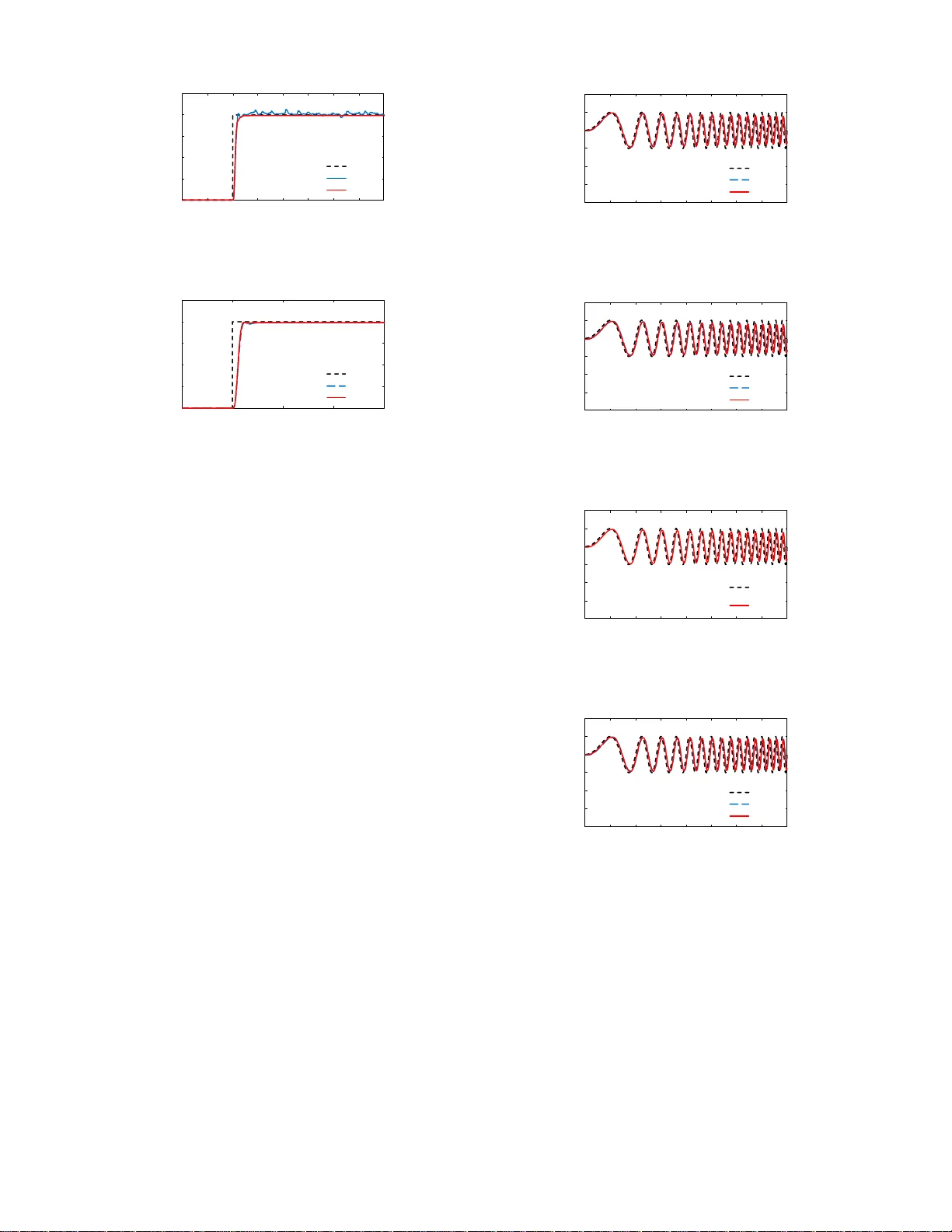
Design of Resonance Ratio Control with Relativ e P osition Informat ion f or T wo-inertia System Kenta Araake 1 , Sho S akaino 2 and T oshiaki Tsu ji 3 Abstract — T wo-inertia systems are prone to resonance vibra- tions that degrade their control perfo rmances. Th ese un wanted vibrations can be effectiv ely suppressed by co ntrol methods based on a disturb ance observer (DOB). Vibration suppression control methods using the information of both the motor and load sides hav e been widely researched in r ecent years. Methods that exploit th e spring deflection or torsional for ce of two-inertia systems hav e deli ver ed p romising perf ormances. Howe ver , few con ventional methods h a ve exploited th e relativ e position in for mation, and the discussion of position control is currently insufficient. F ocusing on the re lativ e p osition, this study proposes a new resonance ratio control (RRC) b ased on the relativ e acceleration and state fee dback. The structu re of the pro posed RRC is derived theore tically and the pr oposed method is experimentally validated. I . I N T RO D U C T I O N High-per forman ce position or veloc ity control has a d - vanced alongside the d evelopment of actuator s, central pro- cessing units, and sensors. Desp ite of th e large progr ess of these technolo gies, th e resonanc e problem remains a major problem because resonanc e vibration s (wh ich depend on the mechanica l system) d egrade th e contr o l performan c e . Resonance is especially strong ly in ro bots with flexible joints, in which the actuators and loads are con n ected by elastic compo nents. Those systems are o f ten modeled as two- inertia systems shown in Fig. 1. T yp ic a l examples are tim in g- belt systems [1], series elastic actuators [2], [3], hydraulic actuators [4], and many o f robo t joints with gears [5]. Therefo re, imp roving the contr ol perfo r mance of two-inertia systems has been the subject of many researches [6] [7] [8] . Many of th e existing vibration sup pression con trollers for two-inertia systems exploit the robustness of a disturban ce observer (DOB) [9] [1 0]. Th e author s of [ 10] improved the robustness of a contr o ller by installing an accelerometer at the load side. Y uki et al. [11] proposed a m ethod for vibration suppression by resonance ratio control (RRC) based on a DOB. The RRC in creases the resonance freque n cy by lowering the mass of th e m otor side of the two-inertia system. Howe ver , the RRC is not robust again st distur bances b ecause the load side inform ation is estimated by a state observer . 1 Ke nta Araak e is a student with the Graduate School of Science and Engineering, Saitama Uni versit y , 255 Shimo-Okubo, Sakura-ku, Saitama City , Saitama 338-8570, Japan email: k.araake.362@ ms.saitama-u. ac.jp 2 Sho Sakaino is with the Graduate School of Systems and Information E ngineeri ng, Uni ver sity of Tsukuba, 1-1-1 T ennodai , Tsukuba, Ibaraki 305-8577, Japan and the JS T PRESTO em ail: sakaino@iit.t sukuba.ac.jp 3 T oshiaki Tsuji is with the Graduat e School of Science and Engineerin g, Saitama Uni versit y , 255 Shimo-Okubo, Sakura-ku, Saitama City , Saitama 338-8570, Japan email: tsuji@ees.saitam a-u.ac.jp ܯ ܯ Lo ad sid e Moto r sid e ܭ ௦ Sp ring ݔ ݔ ܨ ܨ ௦ ܨ ௦ Fig. 1. Model of a two -inerti a system Another effective c o ntrol aga inst r esonance is self-re so nance cancellation (SRC), which can cels th e resonance using the center o f gravity o f the m otor and load sides o f a two-iner tia system [12]. Self-reson ance c a ncellation DOB (SRCDOB), which uses the in formatio n of the motor and th e loa d side s, promises to solve the robustness prob le m . Ho wev er , b o th SRC and SRC DOB req uire the accur a te id e ntification of many parameters. Any id e ntification errors deteriorate the control perform ance. Other effecti ve vibration suppression methods are fu ll-state fe e dback controllers [13]. Full-state feedback con trollers u se the inf o rmation of both th e moto r and the load side s. The full-state feedb ack co ntrol prop osed in [1 3] em ploys a full-state feedback contro ller based on a n ew state equation using the relative velocity be twe e n the mo tor an d load sides, witho ut req uiring the motor side position. Con seq uently , this design achieves stable p o sition control even in systems with an gular drift. Sev eral rece n t control m ethods exploit th e sp ring deflec- tion or torsional force of a two-inertia system. A DOB con- sidering the spring deflection is more robust aga inst mod eling errors. It also delivers b etter fo rce contro l of a two-inertia system than general DOBs usin g the inf o rmation of the moto r sides [14]. Th e authors of [15] p roposed a redu ced-or der DOB (R ODOB) that explo its the spring def ormation of two- inertia sy stem s, and captures on ly th e reson ance frequen cy . The RODOB metho d requ ir es fewer parameters than gen eral DOBs, enabling easier system id e n tification. In addition, high r o bustness and precise force control has been r eported in an RRC with a torsio n al torque sensor, which mon itors the torsional fo rce in two-inertia systems [1 6]. The contr o l methods in [14], [15], and [16] use the relative po sition informa tio n, but p o sition co ntrol has n ot been discussed. T o ܭ ௦ ܭ ௧ ܨ ܫ ݔ ݔ Load side Moto r side ܨ ܨ ௦ ݔ Fig. 2. Block diagram of the two-ine rtia system address this deficiency , this paper propo ses a new RRC with relativ e position informa tion an d a state feedbac k con troller . Specifically , we integrate R ODOB with RRC fo r ro bust position contro l. The propo sed method is e xperimen tally validated. The r e m ainder o f this p aper is struc tured as follows. Section II, describes mod el o f a two-inertia system. The new RRC with re lati ve position info rmation is pr oposed in section II I. The pr oposed metho d is experimentally validated and discu ssed in section IV . Section V conclu des the paper . I I . T W O - I N E RT I A S Y S T E M Many mo d ern indu strial rob ots and mecha tr onics systems transmit force s through a series of g ears or b elts between th e motors and loads. Especially , if the transmitters between the motors a n d loads are flexible structur es, they are mo deled as tw o-inertia systems, which are liable to degradation of control perfo rmance. A two-inertia system model is shown in Fig. 1. The system consists of a m otor mass M m (the in put edge) and a lo ad mass M l (the outp u t ed ge) con nected b y a flexible structure modeled as a sp ring. F re f and F s represent referen ce motor for ce and spring f o rce, respectively . Denoting the mass and position as M m and x m respectively on the motor side and M l and x l respectively on the lo ad side, and rep resenting the sprin g coefficient K s , the equation s ar e giv en by M m ¨ x m = − K s ( x m − x l ) + F re f − F d is m (1) M l ¨ x l = K s ( x m − x l ) − F d is l (2) where F d is m and F d is l represent distu r bance fo rce of the motor and load side, respectively , and the damp ers o f the systems are ignored to simplify the discussion. Fig. 2 is a b lock diagram of the system, I re f and F re f are the current and force of the in puts on the mo tor side, respe c ti vely , K t is the force coefficient of the m otor, and F l is the extern al for ce on the lo ad side. T he relative p osition x r is define d as f ollows: x r = x m − x l (3) F s = K s x r (4) where F s represents th e spr in g force. ିଵ ௗ T wo-iner tia system ௗ ௗ௦ 'LVWXUEDQFH 2 EVHUYH U 1 Fig. 3. Block diagram of standard resonance rati o contro l From Fig. 2, the tran sfer f u nctions from the force refere n ce F re f to the po sition x m at the motor side, and fro m F re f to the po sition x l at th e load side ar e respectively calculated as follows: x m F re f = 1 M m s 2 s 2 + ω 2 z s 2 + ω 2 p (5) x l F re f = 1 M m s 2 ω 2 z s 2 + ω 2 p (6) where ω p and ω z respectively d e note the resonance an d antiresonan ce frequen cies as f ollows: ω p = s K s 1 M m + 1 M l (7) ω z = r K s M l . (8) I I I . D E S I G N O F T H E P RO P O S E D C O N T RO L L E R A. Reson ance ratio contr ol One known vibr ation sup pression control is resonance ratio contro l (Fig. 3), wh ich co nsists of a f eedback con troller and a DOB based on resonance freq uency of the two-inertia system [11]. Here, F cmd is the for c e comm and and K is th e RRC g ain, which mu st b e pro perly designed . The nomin al dynamics P mn ( s ) o n the spr in g-less moto r side are given b y P mn ( s ) = 1 M mn s 2 (9) where the subscript n means the no minal value. L d ( s ) is the low pass filter (LPF) used in the DOB and expressed as L d ( s ) = g / ( s + g ) , an d g is the cut-o ff freq u ency of the LPF . DOBs generally emphasize the resonance in two-inertia systems by stif fen in g the motor side, in cluding vibratio n at load side. Under RRC, the estimated d isturbance ˆ F d is m calculated b y the DOB is fed back by a factor of 1 − K . Meanwhile the reference fo rce F re f is mu ltip lied by K before inputting to the mo to r . The mo tor mass is thus r educed by a factor of 1 / K , severely su ppressing the in duced vib rations. B. Pr o posed resonance r atio co ntr ol based on relative posi- tion This propo sed contro l method uses the relative p osition x r , represented as x r = x m − x l . The tr ansfer fun ction P r ( s ) fro m ௗ T wo-inertia system ௗ௦ ଶ 1 Fig. 4. Block diagram of the proposed m ethod the force re ference F re f to the re la tive po sition x r is given by P r ( s ) = x r F re f = 1 M m ( s 2 + ω 2 p ) . (10) As mention ed a b ove, two-inertia systems based on the rel- ativ e po sition are regard ed as seco nd-or der sy stem s. Her e , considerin g a case where d isturbance s occu r on th e m otor and lo ad side. Eqs. (1), (2), (5), and (6) derives the mo tor position x m as fo llow: x m = 1 M m s 2 1 s 2 + ω 2 p { ( s 2 + ω 2 z )( F re f − F d is m ) − ω 2 z F d is l } . (11) On the other h and, the relative po sition x r represent as Eq. (12) by Eq s. (1), ( 2), (5), and ( 6) when disturbances occur on the m otor and load side. x r = 1 M m ( s 2 + ω 2 p ) ( F re f − F d is m + M m M l F d is l ) (12) Eqs. (1 1) an d (12) show th at the d isturbances are affected by the fo urth-o rder system, in the motor po sition; h owe ver, in the relativ e po sition, the d isturbance s are af fected by the second-o rder system. Th erefor e , focusing on the r elativ e position lea ds to sup pressing th e in fluences o f disturb ance and raising highe r cu toff freq uency o f DOB. The DOB in the propo sed method counterac ts th e d istur- bance caused by the spr ing force . Fig . 4 is a block d iagram of the pro posed RRC. Here, ˆ F r represents the estimated spring force, including the disturbances. As shown in the fig ure, only one param eter , M m , must be iden tified, which g reatly simplifies the m ethod. The RRC essentially modifies the two- inertia system g overned by (1) and (2) into a d ifferent sy stem with th e following state equ ations: ˙ x x x = A A Ax x x + b b bu (13) y y y = c c cx x x (14) A A A = 0 1 0 0 − K ′ s M ′ m 0 K ′ s M ′ m 0 0 0 0 1 K ′ s M ′ l 0 − K ′ s M ′ l 0 (15) b b b = h 0 1 M ′ m 0 0 i T (16) x x x = x m ˙ x m x l ˙ x l T (17) c c c = 0 0 1 0 (18) where M ′ m , M ′ l , and K ′ s denote the motor mass, the load mass, and th e spr in g coe fficient mo dified by the pro posed RRC, respectively . These par ameters are resp e ctiv ely calculated as follows: M ′ m = M m K (19) M ′ l = K ( M m + M l ) − M m K (20) K ′ s = K ( M m + M l ) − M m K M l K s . (21) As described above, the moto r m ass M m in the prop osed RRC is on ly 1 / K times the orig in al motor mass. Howe ver, as sh own by Eqs. ( 1 9) and (20), the total mass M m + M l = M ′ m + M ′ l is u nchan g ed. Mo reover , Eq. (22) (d erived fro m Eqs. (2 0) and ( 21)) co n firms that pole o n the load side is also unmod ified. Therefo re, the resonanc e frequen cy of the modified system ω ′ p is exp r essed as follows: K ′ s M ′ l = K s M l (22) ω ′ p = s K K s 1 M m + 1 M l = √ K ω p . (23) I V . E X P E R I M E N T S A N D D I S C U S S I O N A. Exp erimental setup This sub section de scribes th e exper imental setup of the two-inertia system. Th e system co mprises a linear actuato r, a load, and a spring co nnecting the motor to the load (see Fig. 5). The system can be equ ipped with a weight, as shown in Fig. 5 (b). Th e lin ear actuato r , S1 60Q(GHC), pro duces a force up to 80 N. The positions of the moto r an d load were measured by ab solute linea r en coders with a re so lution o f 50 nm , and a con trol period was 0 . 1 m sec. The param eters derived from the system r e sponses to pseudo random binary signal inputs. Due to the limited movable range, the binary signals 0 and 1 were set to 10 N and 20 N respectively , or to -1 0 N and -2 0 N, respectively , as specified in [17]. By setting 10 N instead of 0 N as th e low binary sign al, we can ignore th e static friction fo th e sy stem. The identified sy stem parameters obtained in the absence and pr esence of the weight ar e shown in T ables I and II, respectively . Noting that the id entified values of the moto r Fig. 5. E xperiment al setup T ABLE I S Y S T E M PA R A M E T E R S W I T H O U T A W E I G H T K t Force coef ficient 33.0 N/A M m Mass (motor side) 1.20 kg M l Mass (load s ide) 1.09 kg K s Spring coef ficient 4662 N/m f p Resonanc e frequenc y 14.4 Hz f z Antiresona nce frequenc y 10.4 Hz T ABLE II S Y S T E M PA R A M E T E R S W I T H A W E I G H T M m Mass (motor side) 1.26 kg M l Mass (load s ide) 1.59 kg K s Spring coef ficient 4917 N/m f p Resonanc e frequenc y 13.3 Hz f z Antiresona nce frequenc y 8.85 Hz mass an d the spr in g coefficient also changed wh en ad ding a weight. B. Contr ol g ain The proposed method includ es a n ewly designed RRC and an outer PD loop fo r state feed b ack control. This subsectio n describes the gain of the im plemented c ontrol. Figure 6 is the whole block diagram of the p roposed method. Here, the subscripts res an d cmd denote the r esponse and comman d values, respectively . The gains K pm ( K d m ) a n d K pl ( K d l ) denote the p ropor tional (deriv ativ e) gains of th e m otor and load, respectiv ely . The four gains are re p resented as fo llows: f = K pm K d m K pl K d l (24) u = − f x (25) ௗ T wo-inert ia system ௦ ௦ ௦ ௗ ௗ ௗ ଶ 1 Fig. 6. Whole block diag ram of the proposed method where u is the input fo rce in E q. ( 1 3). From Eqs. (13), (24), and (2 5), the transfer fun ction from th e refer ence force to the lo ad po sition T ( s ) is derived as follows: T ( s ) = x res l F re f = K 2 K s M m M l s 4 + a 3 s 3 + a 2 s 2 + a 1 s + a 0 (26) a 3 = K K d m M m (27) a 2 = K ( K s M m + M l ( K s + K pm )) M m M l (28) a 1 = K K s ( K d m + K d l ) M m M l (29) a 0 = K K s ( K pm + K pl ) M m M l . (30) In all exp e r iments of this paper, we selected a quadr u ple pole on α . Th e feedb ack gains were selected as follows: K pm = 6 α 2 M m M l − K K s ( M m + M l ) K M l (31) K pl = M m ( α 4 M 2 l − 6 α 2 K s M l ) + K K 2 s ( M m + M l ) K M l K s (32) K d m = 4 α M m K (33) K d l = M m ( 4 α 3 M l − 4 α K s ) K K s . (34) C. Ex periments This subsection validates the propo sed RRC in series of experiments. For exact comparison s with th e con ven tional RRC, for contro ller of the co n ventional RRC was designed with full-state feedb ack (as in the pr oposed RRC), and the resonance fr equency to be modified was the same in b o th RRCs. The po le o n α of the state feedb ack was also identica l in both RRCs. The contro l p arameters of the co n ventional and propo sed m ethods are shown in T ables III and IV, respectively . Because the disturbances in the conventional method have the forth- order character istics as shown (1 1), we cou ld not set sufficiently high DOB g a in . Howe ver, because those in the proposed m ethod have the second-o rder characteristics as shown in (12), we could set a DOB gain as far greater than the resonance fre q uency . T ABLE III C O N T R O L PA R A M E T E R S O F T H E C O N V E N T I O N A L M E T H O D g l Gain of pseudo dif ferential 3000 rad/s g d Gain of DOB 100 rad/s α Quadruple pole 90 rad/s K Resonanc e ratio gain 4.40 f ′ p Resonanc e frequenc y modified by RRC 23.3 Hz M ′ m Motor side mass modified by RRC 0.273 kg T ABLE IV C O N T R O L PA R A M E T E R S O F T H E P RO P O S E D M E T H O D g l Gain of pseudo dif ferential 3000 rad/s g d Gain of DOB 500 rad/s α Quadruple pole 90 rad/s K Resonanc e ratio gain 2.62 f ′ p Resonanc e frequenc y modified by RRC 23.3 Hz M ′ m Motor side mass modified by RRC 0.458 kg M ′ l Load side mass modified by RRC 1.83 kg K ′ s Spring coef ficient modified by RRC 78 36 N/m 1) Re fer enc e r esponses: Th e step refer ence respon ses under the conditions of Fig. 5 (a) are shown in Fig. 7. No significan t differences b etween the con ventional and propo sed RRCs are evident. When the in fluences of the disturbanc e s (inclu ding th e modelin g er ror) were small, the control perform ances o f the two RRCs were almost id entical. 2) P a rameter V ariation: T o con firm th e robustness ag ainst parameter variations, the step r esponses were mon itored for different values o f the control p arameters. Figures 8 a nd 9 sh ow the resu lts of multiplyin g the original mo tor mass by 0.5 and 1 .5 times, respectively . The responses of both RRCs were ro bust to having the 0.5 tim es modele d moto r mass (Fig. 8). Howe ver, wh en the modeled m otor mass was increased 1.5 times, the resp o nse of the conventional RRC developed oscillations while the prop osed RRC re mained sta- ble (Fig. 9). The resu lts confirm that th e propo sed RRC was highly robust against modelin g er rors, and we ll suppre ssed the vibration s at the load sid e po sition owing to the second - order characte r istics of the d istur bances and the high DOB gain. 3) Loa d weigh t variation: T o clarify the effects o f vari- ation of varying the load weight, we monitored the step responses und er the con ditions of Fig. 5 (b) and T able II for different ma sses on the load side. The results a r e shown in Fig. 10. Here, the control paramete r s (state f eedback gain and motor mass o f the DOB) wer e unchang ed from tho se o f the previous experim e n ts, so the re sult confirms the ro bustness to load mass variations alone. Comp a ring Fig s. 10 and 7, both RRCs developed slight v ibrations under the higher load mass, but both wer e strong ly robustness against loa d weigh t variations. 4) Chirp responses: T o confirm the responses against frequen cy variations, th e ch irp signal r esponses were mon i- tored. Figure 1 1 shows th e result using nominal mo to r mass, and no significant differences between the conventional and propo sed RRCs are evident. Th e results of multiply ing the original motor mass by 0.5 and 1 . 5 times, r espectiv ely , are 0 0.01 0.02 0.03 0.04 0.05 1 1.5 2 2.5 3 3.5 4 4.5 5 Load po s i ti o n [m ] Ti me [s] Reference Conv. Prop. Fig. 7. Step responses in the conv entional (blue ) and proposed (red) RRCs. The black dotte d response is the reference step response 0 0.01 0.02 0.03 0.04 0.05 1 1.5 2 2.5 3 3.5 4 4.5 5 Load po s i ti o n [m ] Ti me [s] Reference Conv. Prop. Fig. 8. Step responses under the condit ion of M mn = 0 . 5 M m shown in Figs. 12 an d 13. Th e both RRCs sho w e d the robustness in Fig. 12; howe ver , when the modeled moto r mass was multiplied 1.5 times, the result of th e con ven tional RRC was no t o b tained b ecause the motor wen t out of control and could not m ove. On the other hand , the response of the propo sed RRC was robust to having 1 .5 tim es modele d moto r mass as shown in Fig . 13. Figur e 14 shows that both RRCs have the robustness against load ma ss v ibrations as the step responses in Fig. 1 0. V . C O N C L U S I O N This study proposed a new RRC tha t u ses the r elativ e position infor m ation and state feedb ack. Th is m ethod alters the d ynamics o f the standard two-inertia system. The struc- ture of the prop osed RRC was th eoretically der iv ed, and was confirm ed to tolerate h igher cutoff f requen c ies of DOBs than standard two-inertia systems. The state f eedback gains were also th eoretically derived. Although the co n ventional RRC usin g state f eedback p r ovides excellent responses u nder many conditions, the propo sed RRC ( u nlike th e conv entional design) ensur e s ro bustness against disturb ances in modeling error, owing to the high cutoff freq uency o f its DOB. The experimental re su lts co nfirmed th e validity o f the prop osed RRC. AC K N O W L E D G M E N T This work was sup ported by the JST PRESTO Grand Number JPMJPR1755 , Japan. R E F E R E N C E S [1] A. Hasega wa, H. Fujimoto, and T . T akahashi, “Robot joint angle control based on Self Resonance Cancellat ion using double encode rs, ” in 2017 IEEE Internationa l Conferenc e on Adva nced Intellige nt Mechat ronics (AIM), Munich, Germany , 2017, pp. 460-465. 0 0.01 0.02 0.03 0.04 0.05 1 1.5 2 2.5 3 3.5 4 4.5 5 Load po s i ti o n [m ] Ti me [s ] Reference Conv. Prop. Fig. 9. Step responses under the condit ion of M mn = 1 . 5 M m 0 0.01 0.02 0.03 0.04 0.05 1.5 2 2.5 3 3.5 Load po s i ti o n [m ] Ti me [s] Reference Conv. Prop. Fig. 10. Step responses under a dif ferent load weight [2] G. A. Prat t and M. M. Will iamson, “Series elastic actuators, ” in Proceedi ngs 1995 IEEE /RSJ Internati onal Conferenc e on Intellige nt Robots and Systems. Human Robot Inte ractio n and Cooper ati ve Robots, 1995, vol . 1, pp. 399-406 vol.1. [3] E. Sariyildiz, G. Chen, and H. Y u, “ An Accelerati on-Based Robust Motion Controller Design for a Nove l Series E lastic Actuator , ” IEEE Tra nsaction s on Industria l Electroni cs, vol. 63, no. 3, pp. 1900-1910, Mar . 2016. [4] T . Sakuma, K. Ts uda, K. Umeda, S. Sakaino, and T . Tsuji, “Modeling and resonance suppression control for electro-hyd rostatic actuator as a two-mass resonant system, ” Advance d Robotics, vol. 32, no. 1, pp. 1-11, Jan. 2018. [5] Y . Hirano, T . Y oshioka, K. Ohishi, T . Miyaza ki, Y . Y okokura, and M. Sato , “V ibration Suppression Contro l Method for Trochoida l Reduct ion Gears under Load Conditions, ” IEEJ Journal of Industry Applica tions, vol. 5, no. 3, pp. 267-275, 2016. [6] Y . Hori, “2-Inert ia System Control using Resonance Ratio Control and Manabe Polynomial s, ” IE EJ Trans. IA, vol. 114, no. 10, pp. 1038- 1045, Sep. 1994. [7] S. Y amada, H. Fujimoto, and Y . T erada, “Joint torque control for backla sh compensati on in two-inert ia system, ” in 2016 IEEE 25th Interna tional Symposium on Industrial Electronics (ISIE), Santa Clara, CA, USA, 2016, pp. 1138-1143. [8] K. Tsuda, T . Sakuma, K. U m eda, S. Sakaino, and T . Tsuji, “Resonan ce-suppre ssion Control for Electro-hydro static Actuator as T wo-ine rtia System, ” IEEJ Journal of Industry Applicati ons, vol. 6, no. 5, pp. 320-327, 2017. [9] K. Ohnishi, “Robust Motion Control by Disturbance Observ er , ” JRSJ, vol. 11, no. 4, pp. 486-493, May 1993. [10] R. Oboe and D. Pilastro, “Use of load-side MEMS acceler ometers in servo positioning of two-mass-spring systems, ” in IECON 2015 - 41st Annual Conferenc e of the IEE E Industrial Electronics Societ y , Y okoha ma, 2015, pp. 004603-004608. [11] K. Y uki, T . Murakami, and K . Ohnishi, “V ibration Control of a 2 Mass Resonant System by the Resonance Ratio Control, ” IEEJ Tran s. IA, vol. 113, no. 10, pp. 1162-1169, O ct. 1993. [12] M. Aoki, H. Fujimoto, Y . Hori, and T . T akaha shi, “Robust resonance suppression control based on self resonance cancell ation disturbance observe r and applic ation to humanoid robot, ” in 2013 IEEE Interna - tional Conference on Mechatronics (ICM), V icenza, 2013, pp. 623- 628. [13] S. Sakaino and T . Tsuji, “Resonan ce Suppression of Electro- hydrostat ic Actuator by Full State Feedback Controlle r Using Load- side Information and Relati ve V elo city , ” IF AC-P apersOnLine , vol. 50, no. 1, pp. 12065-12070, Jul. 2017. 0 0.01 0.02 0.03 0.04 0.05 0.06 3 4 5 6 7 8 9 10 11 Load po s i ti o n [m ] Ti me [s] Reference Conv. Prop. Fig. 11. Chirp responses 0 0.01 0.02 0.03 0.04 0.05 0.06 3 4 5 6 7 8 9 10 11 Load po s i ti o n [m ] Ti me [s] Reference Conv. Prop. Fig. 12. Chirp responses under the conditio n of M mn = 0 . 5 M m 0 0.01 0.02 0.03 0.04 0.05 0.06 3 4 5 6 7 8 9 10 11 Load po s i ti o n [m ] Ti me [s] Reference Prop. Fig. 13. Chirp response under the condition of M mn = 1 . 5 M m 0 0.01 0.02 0.03 0.04 0.05 0.06 3 4 5 6 7 8 9 10 11 Load po s i ti o n [m ] Ti me [s] Reference Conv. Prop. Fig. 14. Chirp responses under a diffe rent load weight [14] S. Oh, C. L ee, and K. Kong, “Force control and force observer design of series elastic actuato r based on its dynamic charac teristi cs, ” in IECON 2015 - 41st Annual Conference of the IEEE Industrial Electroni cs Society , Y okohama, 2015, pp. 004639-00464 4. [15] H. Lee and S. Oh, “Design of reduced order disturbanc e observer of series elasti c actuat or for robust force control, ” in 2018 IEEE 15th Interna tional W orkshop on Advance d Motion Control (AMC), T okyo, 2018, pp. 663-668. [16] Y . Y okokura and K. Ohishi, “Si ngle inertializ ation of a 2-inertia system based on fine torsional torque and sensor-based resonance ratio control lers, ” in 2017 IEE E Internat ional Conferenc e on Mechatroni cs (ICM), Churchill, Australia, 2017, pp. 196-201. [17] T . Y amazaki, S. Sakaino, and T . Tsuji, “Estimation and Kinetic Modelin g of Human Arm using W earable Robot Arm, ” Electrical Engineeri ng in Japan, vol . 199, no. 3, pp. 57-67, May 2017.
Original Paper
Loading high-quality paper...
Comments & Academic Discussion
Loading comments...
Leave a Comment