Knee Compliance Reduces Peak Swing Phase Collision Forces in a Lower-Limb Exoskeleton Leg: A Test Bench Evaluation
Powered lower limb exoskeletons are a viable solution for people with a spinal cord injury to regain mobility for their daily activities. However, the commonly employed rigid actuation and pre-programmed trajectories increase the risk of falling in c…
Authors: Stefan O. Schrade, Marcel Menner, Camila Shirota
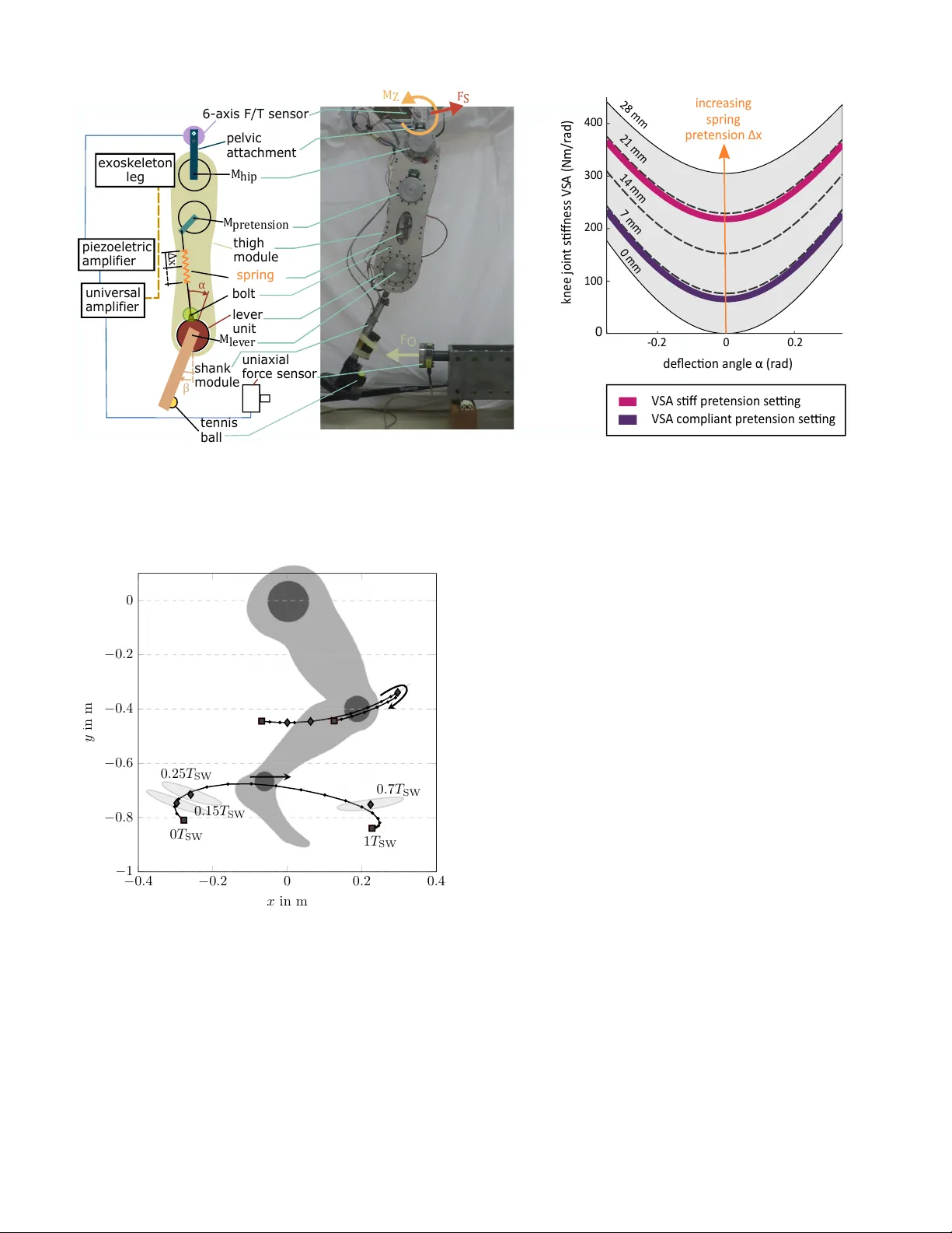
Knee Compliance Reduces P eak Swing Phase Collision F or ces in a Lower -Limb Exoskeleton Leg: A T est Bench Evaluation Stefan O. Schrade, Marcel Menner , Camila Shirota, Peter W iniger , Alex Stutz, Melanie N. Zeilinger, Oli vier Lambercy and Roger Gassert Abstract —Power ed lower limb exoskeletons are a viable so- lution f or people with a spinal cord injury to regain mobility for their daily activities. However , the commonly employed rigid actuation and pr e-programmed trajectories increase the risk of falling in case of collisions with external objects. Compliant actuation may reduce for ces during collisions, thus protecting hardwar e and user . Howe ver , experimental data of collisions specific to lower limb exoskeletons are not av ailable. In this work, we in vestigated how a variable stiffness actuator at the knee joint influences collision for ces transmitted to the user via the exoskeleton. In a test bench experiment, we compared three configurations of an exoskeleton leg with a variable stiffness knee actuator in (i) compliant or (ii) stiff configurations, and with (iii) a rigid actuator . The peak torque observed at the pelvis was reduced fr om 260.2 Nm to 116.2 Nm as stiffness decr eased. In addition, the mechanical impulse was r educed by a factor of three. These results indicate that compliance in the knee joint of an exoskeleton can be favorable in case of collision and should be considered when designing power ed lower limb exoskeletons. Overall, this could decrease the effort necessary to maintain balance after a collision and improved collision handling in exoskeletons could result in safer use and benefit their usefulness in daily life. Index T erms —Robot Collision, Powered Exoskeletons, Gait Rehabilitation, V ariable Impedance Actuation, Series Elastic Actuation, Compliant J oints I . I N T R O D U C T I O N Many people are limited in their mobility after surviving a spinal cord injury (SCI). Wheelchairs are the state-of- the-art solution to regain mobility if ambulation is difficult or no longer possible. Aside from challenged mobility , the SCI population suffers from increased risk of experiencing secondary health problems such as cardio-pulmonary diseases, obesity and musculoskeletal degeneration [1]. Some of these are thought to be fostered by the inability to stand and walk [2], [3]. Hence, po wered lower limb exoskeletons could mitigate some of these ef fects as they allo w the user to regain the ability to walk. Such devices are av ailable for use in clinics (e.g. Ekso and EksoGT , Ekso Bionics, USA) [4], [5] and also home en vironments (ReW alk Personal 6.0 and ReW alk Rehabilitation, ReW alk Robotics, USA) [6], [7]. S.O. Schrade, C. Shirota, O. Lambercy , and R. Gassert are with the Rehabilitation Engineering Laboratory , ETH Zurich, 8092 Zurich, Switzerland { stefan.schrade,camila.shirota, olivier.lambercy,roger.gassert } @hest.ethz.ch M. Menner and M.N. Zeilinger are with the Institute for Dy- namic Systems and Control, ETH Zurich, 8092 Zurich, Switzerland { mmenner,mzeilinger } @ethz.ch A. Stutz and P . Winiger are with the Laboratory for Mechani- cal Systems Engineering, Swiss Federal Laboratories for Materials Sci- ence and T echnology EMP A D ¨ ubendorf, 8600 D ¨ ubendorf, Switzerland { peter.winiger,alex.stutz } @empa.ch Powered lo wer limb exoskeletons are attached to the legs, pelvis and sometimes torso of the user . The exosk eleton mov es the user’ s biological legs with its mechanical legs while supporting the upper body . Most de vices are anthropomorphic and actuate hip and knee joints in the sagittal plane, flexing and extending these joints. Crutches or other walking aids are used for balancing and to compensate for missing active ankle joints. T ypically , exoskeletons are actuated with electric motors and high reduction ratio gearboxes, which enable high torques and precise position control. The movements are pre-programmed fix ed position or v elocity controlled tra- jectories [8]–[10] or, more seldomly , torque controlled tra- jectories [11]. Since most movement patterns were designed for even terrain, rigid actuation in combination with the fixed patterns can lead to unsuitable control in unstructured en vironments as those encountered during daily life activities. The exosk eleton can typically not detect obstacles and may collide with them during swing, or force the leg to further extend on unev en ground despite already having established ground contact. In both cases, the user will likely be pushed backwards, leading to uncomfortable or e ven unsafe situations. In the worst case, falls may be induced if the user cannot compensate the inappropriate control with the walking aids. A particularly challenging and potentially dangerous situ- ation is when an obstacle hinders forward leg swing during exoskeleton walking. Noticing and reacting to such collisions is especially challenging for users with motor complete SCI as they often also hav e impaired sensory perception. In contrast, unimpaired humans are capable of quickly and smoothly stepping o ver obstacles or prematurely terminating the swing phase to regain balance [12]. Current exoskeletons, ho wev er , are not able to detect and react to collisions. The robotics community has studied collisions [13], added collision av oidance [14] as well as detection [15], [16], and implemented mitigation strategies [15], [16] to address this issue. Dealing with collisions becomes ev er more important as robots lea ve well-controlled and structured factory environ- ments, as is the case for exoskeletons. Rendering joints compliant has been suggested to reduce the sev erity of impacts [17]–[19]. This can be achiev ed either with mechanical designs or through control. If compliance is emulated through control, sensing and actuation could be too slow or not robust enough to react to the fast dynamics of collisions [17], and high peak forces that can damage the hard- ware and may be dangerous to users. Hence, implementing a mechanical compliance may be more desirable. This has been suggested for assistiv e devices for walking [20]–[22]. Howe v er , the influence of compliance in joints has not yet been experimentally in vestigated. In general, robot collision experimental data are scarce. Povse et al. [23] in vestig ated damage to human soft tissue that may be induced from collisions between humans and robots. Haddadin et al. [17] took the approach one step further and ga ve the robot sharp tools to inv estigate how collisions between robots and humans can be rendered safe. Park et al. [19] found that a nonlinear spring integrated in the robot joint may significantly reduce the risk of head injury in case of a collision between a robot arm and a human head. Ho wev er , none of these studies are specific to the application of lo wer limb exosk eletons. Simulation results [24] motiv ated our hypothesis that the peak forces experienced by the user would be decreased in amplitude and delayed with a soft joint in comparison to a rigid one. Decreased force amplitude could reduce the need to compensate for collision forces and torques, which could simplify keeping balance. Delayed peak forces would give more time to the user and controller to react to collisions. Thus, the goal of this w ork was to in vestigate the influence of joint compliance on the resulting interaction forces and torques for lower limb exoskeletons. W e in vestig ated swing phase collisions with one leg of the V ariLeg exoskeleton [8] on a test bench setup using three different stif fness levels: two were rendered with the VSA and the third, representing a conv entional rigid joint, by blocking the VSA. As outcome parameters, we measured the collision force at the obstacle, the torque and the resulting force acting at the attachment point of the leg to the test frame at the pelvic level in the plane of movement (sagittal plane). The latter were moti vated by the assumption that the forces and torques at the pelvic le vel would be comparable to the forces and torques that w ould be transmitted to a user of the exoskeleton. I I . M E T H O D S A. The V ariLe g Exosk eleton Le g The V ariLe g is a powered lo wer limb exoskeleton designed to restore the walking ability of motor-complete spinal cord injured users [8]. The unique feature of the exoskeleton is the V ariable Stif fness Actuator (VSA) in each knee joint (Fig. 1). These actuators cover a stiffness range similar to the human knee joint [25], and allow v arying it online during walking. The VSA can also be blocked with a bolt, resulting in a con ventionally actuated rigid knee joint. The exosk eleton also has con v entional rigid actuators that allo w hip flexion and extension ( M hip ). For the test bench experiments, the passiv e spring-loaded ankle was replaced with a dumb-bell disk of equi valent to the weight of the exosk eleton ankle and foot (1.5 kg) and a tennis ball substituting the semi-compliant shoe tip and foot. The e xoskeleton has the capability of v arying the knee joint stiffness with a VSA, using the MACCEP A principle [26]. As a consequence, M lev er only directly controls the knee angle β if a bolt is inserted to connect thigh and shank ov er the actuator unit. If the bolt is not inserted, the shank and thigh are compliantly connected through the spring. In this case, M lev er sets the equilibrium position of the knee angle. Thus, the shank may be deflected from its equilibrium position by angle α if external forces are present. The joint compliance can be v aried by pretensioning the spring (i.e. increasing stif fness) with M pretension (Fig. 1, right). For the collision experiments, the leg was suspended from a rigid frame using the attachment point of the pelvic structure of the exoskeleton. A piezoelectric six-axis force and torque sen- sor (T ype 9306A, Kistler Instrumente A G, Switzerland) was placed between the leg and the frame. The piezoelectric signals were amplified and sampled at 10 kHz by a LabAmp 5167A80 (Kistler Instrumente AG, Switzerland). The obstacle was equipped with a single-axis force sensor (GTM 20kN, GTM T esting and Metrology GmbH, Germany). All data were routed to a universal amplifier (HBM MX1615, Hottinger Baldwin Messtechnik GmbH, Germany) and sampled at 19.2 kHz. The exoskeleton logged joint angle data at 100 Hz and sent a trigger signal to the universal amplifier indicating when it was recording. This trigger signal was later used to synchronize the data of the univ ersal amplifier with the data of the exoskeleton. B. Contr ol of the T est Bench Exoskeleton Leg T o focus on the influence of the differing joint stiffness, we relied on feed-forward control to e xecute the swing phase. The controller was designed to be the first layer of control inspired by nature, which features systems that inherently behav e in a desired way , using mostly feed-forward control with appropriate mechanical structure and without feed-back [27] and corresponds to an approach often used in devices with a layered control approach [28]. The exoskeleton leg was torque controlled for this experi- ment. A desired trajectory was found by specifying waypoints that the ankle should pass through at specific times of swing phase (Fig. 2). This trajectory was optimized to satisfy the constraints defined by the waypoints, motor speed limits, and motor torque limits. Feed-forward torque commands were then calculated for ev ery joint stiffness configuration based on a model of the exoskeleton leg to execute the desired motion. This model was deriv ed using Lagrangian mechanics, where the uncertain viscous friction parameters were fitted using experimental data. W e refer the interested reader to the Appendix for more detailed information (Chapter VI). C. Experimental Pr otocol Collisions were performed during swing phase to simulate stumbling ov er an obstacle. The leg w as brought to the initial position and the ex ecution of the swing phase was triggered via a b utton. The obstacle w as placed such that the collisions occurred at the point of maximum forward velocity during swing phase. This point was identified by analyzing the ref- erence trajectory identified by the optimization (Fig. 2). After the collision occurred, the system was shut down manually , cutting the motors of f from the power supply . This was done to prev ent potential damage to the hardware, since the controller had no strategies to mitigate the collision, and since only the time period of the collision w as of interest. Three configurations were tested: Compliant with VSA (COMPLIANT , 65 Nm/rad), stiff with VSA (STIFF , 218 Nm/rad), and VSA blocked (RIGID, abov e 400 200 300 -0.2 0 0.2 knee j oin t s ness V S A (Nm/r ad) de ec on angle (r ad) incr easing spring pr e t ension x 28 mm 21 mm 14 mm 7 mm 0 mm V S A s pr e t ension se ng V S A c omplian t pr e t ension se ng 100 0 Δ x F O M Z F S α Δ x β shank module uniaxi al force sens or tennis ball lev er unit M le v er bolt M pr et ension thigh module spring M hip pelvic atta chment 6- axis F/T senso r ex osk eleton leg univ ersa l ampli fier piez oeletr ic ampli fier Fig. 1. Overview of the setup f or the collision experiments The V ariable Stiffness Actuator (VSA) can be blocked by inserting a bolt (left; green circle). If the VSA is acti ve (not blocked), the pretension motor ( M pretension ) controls joint stif fness by v arying the pretension of the spring (right). Data were recorded from the universal amplifier and the exoskeleton. A shared trigger signal was used to synchronize the data logs of the exoskeleton and the universal amplifier . T wo VSA configurations were used: VSA STIFF and VSA COMPLIANT (right). The collision force F O was measured at the obstacle. At the pelvic lev el the sagittal plane force F S and the pitch torque M Z were measured during the collision. − 0 . 4 − 0 . 2 0 0 . 2 0 . 4 − 1 − 0 . 8 − 0 . 6 − 0 . 4 − 0 . 2 0 1 T SW 0 T SW 0 . 15 T SW 0 . 25 T SW 0 . 7 T SW x in m y in m Fig. 2. T rajectory generation f or the exosk eleton leg The end-point and knee trajectory found by optimization are indicated as curves. W aypoints (diamonds) in the end-point space are specified to be passed within a certain tolerance in position (grey shaded ellipses) and time (specified relativ e to the desired swing phase time T SW but not visible in this plot). The desired movement starts and ends at the squares. The trajectory of the knee joint is not a design parameter, but rather results from the desired end-point trajectory and the optimization performed to achieve this trajectory . 20 kNm/rad according to the Harmonic Dri ve manual 1 ). The 1 The stiffness depends on the torque at the joint; for the torque ranges of 0 to 14 Nm, 14 Nm to 48 Nm, and abov e 48 Nm, the stiffness is approximately 20, 27, 37 kNm/rad, respectiv ely . Source: Harmonic Drive Reducer s Gear Units SHD-2SH Engineering Data STIFF VSA configuration corresponded to a value used in the training sessions described in our previous work [8] where the VSA pretension motor ( M pretension ) was controlled to hold a constant position throughout the whole gait cycle. The COMPLIANT configuration of this experiment also started at this v alue before triggering the step, and reduced during swing phase to mimic human knee joint stiffness modulation [25]. The exoskeleton segment lengths were chosen based on typical segment lengths used in training sessions with our users [8] (thigh length 0.480 m, shank length 0.445 m). W e conducted 15 collisions for each leg configuration. V ideo recordings were acquired for visual analysis of the collisions (GoPro HERO5, GoPro Inc., United States of America) at 120 frames per second. D. Data Analysis Data sets that were corrupted due to setting or measurement errors were rejected (n=2). F orce and torque data were filtered with a second-order Butterworth low-pass filter at 250 Hz using the f iltf ilt command of MA TLAB 2017b (MathW orks, United States of America) and signal offset was removed. Collision onset was defined as the point where the force at the obstacle ( F O ) crossed a threshold of 18 N, based on the sensor noise level. Data from different collisions were aligned in time at collision onset. Individual trajectories were re-sampled at 6.5 kHz and av eraged at each time sample. The per sample standard deviation was also calculated to gauge consistency across measurements. Here, we assumed that the exact torque dependent stiffness of the Harmonic Driv e was not important, as it was orders of magnitude larger than that of the VSA. The movement of the end-point in task space was calculated from the joint angles using forward kinematics. The antero- posterior (x-direction) and vertical (y-direction) speeds were obtained by deri vation of the sampled position data. The total speed w as calculated as: v tot = q v x 2 + v y 2 . (1) The net force in the plane of mov ement (sagittal plane, F S ) and the torque in the sagittal plane (pitch torque, M Z ) were ev aluated. The net amplitude of the sagittal plane forces was calculated as: F S = q F x 2 + F y 2 . (2) Peaks in force and torque and their respectiv e time of occurrence were determined within a 150 ms window after the collision as this was assumed to be the relev ant time windo w and similar time windo ws have been used in other experiments in vestig ating trips [29]. This short time period after collision was not af fected by the manual shutdown of the motors. The area under the curve, which corresponds to the mechanical impulse, was also calculated in the same time window for all three knee joint configurations. The peak force and torque values, their respective time of occurrence and impulse were tested for statistically signifi- cant differences. A Kruskal-W allis test followed by a post hoc multiple comparison test was performed to compare the results across the three different knee joint configurations. The threshold was set to 0.05 for significant differences, stronger significance le v els were indicated if below 0.01 and 0.001. I I I . R E S U LT S The trajectory up to the point of collision was similar for all three conditions (Fig. 3 top), with the COMPLIANT and STIFF (VSA) conditions slightly lower than the RIGID condition. Forward velocity at collision (Fig. 3 bottom left) was 0.52 ± 0.05 m/s (mean ± standard de viation) for the RIGID knee joint. This was slightly lower than the maximum value observed up to the collision of 0.62 m/s. The COMPLIANT and STIFF knee joints achie ved identical forward v elocities at collision of 0.44 ± 0.05 m/s. Upwards velocity (y-velocity) was higher for both VSA collisions than for the RIGID condition. The total v elocity , which, when squared, is proportional to the kinetic energy of the leg before collision, was very similar for all three conditions 0.47 ± 0.04 m/s, 0.47 ± 0.04 m/s and 0.52 ± 0.05 m/s (COMPLIANT , STIFF , RIGID). The collisions with the RIGID knee joint lead to move- ment only in the x-direction, as the end-point bounced back (Fig. 3 bottom left and middle). In contrast, when the knee joint was COMPLIANT or STIFF , the hip continued flexing while the foot slid upwards on the obstacle, which can be seen as the increasing y-v elocity after the collision for both VSA joint configurations (Fig. 3 bottom middle). The statistical analysis of the outcome parameters are pre- sented in T ab . I. The different le vels of statistical significance are also indicated in the boxplots with brack ets. The a verage peak force at the obstacle changed from around 200 (COM- PLIANT), to 260 (STIFF) and finally to 280 N (RIGID) (Fig. 4 T ABLE I R E SU LT S O F T H E S TA T IS T I CA L A NA L Y S IS Base Condition Compared to p-V alue ∆ median Unit Peak Obstacle F orce, F O COMPLIANT STIFF 0.01470 72.4 N COMPLIANT RIGID 0.00000 93.4 STIFF RIGID 0.01494 21.0 Peak Sagittal F orce, F S COMPLIANT STIFF 0.18836 6.3 N COMPLIANT RIGID 0.00000 80.5 STIFF RIGID 0.00066 74.2 Peak Pitch T orque, M Z COMPLIANT STIFF 0.01361 13.8 Nm COMPLIANT RIGID 0.00000 141.1 STIFF RIGID 0.00550 127.2 Peak Timing Obstacle F orce, F O COMPLIANT STIFF 0.34124 -0.0012 s COMPLIANT RIGID 0.00010 0.0456 STIFF RIGID 0.00000 0.0469 Peak Timing Sagittal F orce, F S COMPLIANT STIFF 0.02873 -0.0049 s COMPLIANT RIGID 0.00105 0.0067 STIFF RIGID 0.00000 0.0116 Peak Timing Pitch T orque, M Z COMPLIANT STIFF 0.98080 0.0006 s COMPLIANT RIGID 0.00001 0.0114 STIFF RIGID 0.00001 0.0108 Impulse Obstacle For ce, F O COMPLIANT STIFF 0.01361 5.85 Ns COMPLIANT RIGID 0.00000 13.45 STIFF RIGID 0.00550 7.60 Impulse Sagittal For ce, F S COMPLIANT STIFF 0.01299 1.95 Ns COMPLIANT RIGID 0.00000 3.10 STIFF RIGID 0.00603 1.14 Impulse Pitch T orque, M Z COMPLIANT STIFF 0.01361 5.18 Nms COMPLIANT RIGID 0.00000 11.24 STIFF RIGID 0.00550 6.06 and Fig. 5). The av erage net sagittal peak force was higher for the RIGID knee joint (271.2 ± 5.5 N) compared to the other two configurations with 200.9 ± 7.6 N and 185.9 ± 17.1 N. Pitch torque ( M Z ) values were approximately twice as high for the RIGID knee joint at 260.2 ± 5.0 Nm compared to 132.0 ± 1.8 Nm and 116.2 ± 5.8 Nm for the STIFF and COM- PLIANT knee, respectiv ely . The timing of the peak force and torque at the pelvic le vel was similar (around 0.04 s) for all three knee joint configurations. The peak force at the obstacle, howe v er , occurred at around 0.02 s for the COMPLIANT and STIFF knee joints, but only after 0.06 s with the RIGID knee (Fig. 5). The impulse generally increased with joint stiffness (Fig. 6). For the pitch torque, the COMPLIANT knee resulted in an impulse three times smaller than the RIGID knee joint, and twice as small as the STIFF knee joint. The differences between the configurations in the obstacle force impulse were similar to the pitch torques. In contrast, the difference between the configurations in the impulse of the sagittal plane force was not as large. The incremental increase in the sagittal plane force between the three conditions was around 2 Ns, which corresponds to about 18% of the impulse observed with the COMPLIANT knee joint. Fig. 3. A verage end-point trajectory and velocity from beginning of swing phase until the end of the analysis time window The trajectory for all three configurations started v ery similar and was consistent (top). Circles indicate location of collision, diamonds indicate maximum position in x and squares indicate position at the end of the analysis windo w . At the bottom the velocities in different directions are indicated before and after collision. The black line indicates the start of the collision and the grey area marks the analyzed time window of 150 ms. After collision, the RIGID knee joint caused the ankle to bounce off the obstacle, seen as negati ve x-direction velocity (bottom left) and almost straight average foot trajectory after collision. The COMPLIANT and STIFF joints slid up the surface of the obstacle resulting in an increase in y-direction velocity (bottom middle). I V . D I S C U S S I O N This work aimed to examine the influence of knee joint stiffness of an exosk eleton leg on interaction forces and torques resulting from a collision during swing phase. T est bench measurements were conducted to compare the VSA in the V ariLeg e xoskeleton to a rigid actuation paradigm [8]. As expected, the results sho wed that peak torques, and forces were reduced at the pelvic level when the knee joint was compliant. Additionally , the impulse for all observed forces and torques was reduced when the knee joint was compliant. The noticeable decrease in peak force and torque, and im- pulse transmitted to the user observ ed with the COMPLIANT joint would increase the likelihood of the user being able to counteract these forces and torques with the walking aids. This could pre vent falls and increase safety . Furthermore, the risk to injure the shoulder joints by sudden force and torque peaks during balancing would also be decreased. Lastly , decreased forces and torques acting on the e xoskeleton w ould also decrease the risk of damaging the hardw are. Peak force at the obstacle v aried with joint stif fness although Fig. 4. Collision force at the obstacle and interaction for ce and torque at the hip The average force and torque trajectories were repeatable as suggested by the standard deviation bands. A higher maximum torque at the pelvic lev el can be observed with the RIGID knee (bottom). The maximum collision force at the obstacle varied with knee joint configuration and the peak was achieved later with the RIGID knee (top). Forces in the sagittal plane were slightly higher when the knee was RIGID (middle). theoretical models suggest that the stiffness of the joint should not influence the initial forces of an impact [30]. This could be due to different collision behavior between RIGID joint and VSA joint configurations, as suggested by the different kinematic patterns. From the end-point trajectory , we observed that the COMPLIANT and STIFF knee joints allo wed the leg to start lifting the end-point o ver the obstacle with continued knee and hip flexion after the collision. This is similar to what has been observed in experiments where prosthesis users were tripped during late swing phase [31]. The RIGID knee joint, on the other hand, bounced back from the obstacle as knee flexion was pre v ented by the rigidity . The fact that the leg started to climb over the obstacle despite not being programmed to do so may be beneficial for implementing collision mitigation strategies. A potential strategy to mitigate the effects of stumbling could be to try to lift the leg over the obstacle as humans do [12]. When the leg just bounces off the obstacle and moves backwards, the inertia of the system delays adequate reaction. In that case, all the kinetic energy would hav e to be redirected upwards to step ov er the obstacle or towards the ground, which would increase the risk of falling. If the mechanics of the leg already start to redirect the kinetic ener gy into the correct direction (upwards or do wnwards), the stumbling mitigation can be achie v ed more Fig. 5. Peak for ces and torques during the collision Peak amplitude (top) and timing (bottom) of force at the obstacle (left), sagittal force (middle) and pitch torque (right) with COMPLIANT (C), STIFF (S) and RIGID (R) joint configurations. Median, 25th and 75th percentiles, maximum and minimum values, and outliers are indicated by red line, box edges, whiskers and red crosses, respectively . Statistically significant differences are indicated with a bracket while one, two and three stars indicate p-values lower than 0.05, 0.01 and 0.001, respectiv ely Fig. 6. Collision impulse For the RIGID knee joint, the impulse was clearly highest for all parameters. The COMPLIANT and STIFF VSA configurations showed a bigger difference in impulse of the obstacle force F O and the torque at the hip M Z . In contrast, the difference in impulse was less prominent for the sagittal plane force F S when comparing the two VSA configurations. Statistically significant differences are indicated with a bracket while one, two and three stars indicate p-values lower than 0.05, 0.01 and 0.001, respecti vely . quickly than if the leg were moving backwards. In contrast to our expectations based on [24], the timing of the peaks at the pelvic lev el was not notably delayed at lower le vels of knee joint stiffness. At the obstacle howe v er , the RIGID configuration exhibited a later occurrence of the peak collision force compared to the COMPLIANT and STIFF knee joint configurations. W e hypothesize that this is due to the differing collision behavior . W ith the RIGID configuration, the tennis ball is deformed in an elastic collision and kinetic energy is redirected from a forward movement to a backw ards mov ement. This causes higher penetration depth (more tennis ball deformation) and high forces are transmitted to the obstacle for a longer time. This hypothesis is supported by the impulse that was three times higher for the pitch torque ( M z ) with the RIGID knee joint configuration compared to the COMPLIANT knee joint. It is interesting to note that the dif ference in peak pitch torque was only about 16 Nm comparing the COMPLIANT and STIFF configurations, which is about 10% of the torque observed with the COMPLIANT knee joint. Howe ver , the difference in impulse was much larger as the STIFF knee joint resulted in double the impulse of the COMPLIANT knee joint. Accordingly , lowering the stif fness of the VSA during swing seems to be mostly relev ant to reduce the impulse rather than peak forces and torques caused by collisions. Thus, an SEA offering a fixed mechanical compliance and rendering a broader range via control, similar to the ones used in other legged robots [32], may be sufficient in terms of reducing peak forces and torques. This would allow to reduce the complexity of the actuation system as the motor used to pretension the spring could be omitted, rendering the design lighter . Having some mechanical compliance in the system is most likely necessary , howe v er , as ev en with fast sensing the collision has to be detected first and then acted upon. Actuation system inertia, which is typically high due to the large reduction ratios used in powered lower limb exoskeletons, would not allow adequate reaction to reduce the peaks observed here that occur during the first 150 ms of a collision. In the real application scenario, feed-back control would add disturbance rejection and error minimization. F or our experi- mental protocol howe ver , feed-back control would have led to results that are partially caused by the mechanical structure and partially by the implemented control. Hence, we only used the first layer of control consisting of the feed-forward part. This allowed slight differences in swing phase ex ecution, which could be observed between the configurations. The slightly higher collision point observed with the RIGID knee joint is assumed to not have influenced the results as only the velocity is rele v ant for the kinetic energy at collision. V elocity differences would be more problematic than differing collision height as the velocity squared directly relates to the impulse ov er the kinetic energy in elastic collisions. Accordingly , comparing the total v elocity of the end point at collision, the difference between knee joint configurations seemed ne gligible (0.05 m/s). A different approach would have been to mo ve the obstacle to induce collision at exactly the point of maximum forward v elocity of the leg. Ho we ver , the risk of introducing more v ariability through moving the obstacle between configu- rations led us to rather accept this inaccurac y . Only considering the brief window after collision onset to in vestig ate collisions also ensured that manually stopping the exoskeleton by cutting the motors off the power supply should not have influenced the results. The experiments were performed on a test bench only , with no user attached to the exoskeleton leg. A human user may significantly change the system behavior as passive mass, spring and damper elements are added in parallel to the exoskeleton leg (as a first approximation for non-spastic motor complete spinal cord injured legs). In addition, the torso and arms would react to the collision and interact with the en vironment. The forces that the user would hav e had to counteract to not fall ov er the obstacle were significantly lower in the case of the COMPLIANT knee joint as the interaction torque at the hip was only half as big compared to the RIGID knee joint. Further, we ar gue that the lower impulse with the COMPLIANT knee joint indicated that the overall effort to counteract collision forces would be lower for a user since lower impulse means that less force or torque had to be ex erted during the collision time window . It would be interesting to perform similar experiments with users inside the exoskeleton. Howe ver , this would lik ely increase the variability of the data as the human user might react differently ev ery time. Although non-trivial, this has already been in vestigated in prosthesis users [29]. Besides the technical difficulties, such an experiment would introduce the risk of falling, straining muscles or similar that need to be taken into consideration. A notable difference between amputees and motor complete SCI users of exoskeletons would be that SCI users hav e no sound limb to rely on for recovery [31]. Thus, the e xoskeleton would ha ve to provide all the recovery support. An advantage of using series elasticity is that the elastic elements can be used as torque sensors. De viations of the joint from its equilibrium position during swing phase can be observed to estimate the torque acting on the joint. Stumbling mitigation strategies could be initiated if the de viation from the equilibrium position is larger than a predefined threshold, thus improving fall protection capabilities of exoskeletons. A collision detection algorithm similar to [15] could be implemented with a se- ries elasticity detecting onset of collisions without additional torque sensors. After detection of the collision, the controller could react to it by stepping over the obstacle or trying to prematurely end the swing phase and placing the foot on the floor to step ov er the obstacle with the other leg, similar to what has been de veloped for prostheses [33]. T esting such algorithms on the same test bench setup would yield valuable insight to wards better f all pre v ention. V . C O N C L U S I O N Adding compliance to the knee of a powered lo wer-limb exoskeleton le g reduced peak forces and torques at the pelvic lev el in a test bench collision experiment. Even more, it reduced the impact impulse during the collision, which could reduce the effort a user has to exert to maintain balance. Further lowering stiffness with the VSA during swing phase noticeably reduced impulse, and, to a lesser extent, peak torques and forces at the pelvic level. This suggests that compliance in the range suggested here lead to safer collisions and variations in the VSA stiffness range inv estigated are mostly beneficial to reduce impulse. These findings should inform future designs of wearable lower limb exoskeletons and can help to design joints that are mechanically inherently robust to collisions. This may bring the field one step closer to robots that move as nimbly and swiftly as animals and humans. V I . A P P E N D I X : T R A J E C TO RY G E N E R A T I O N A N D F O L L OW I N G The approach for computing nominal motor commands (feed-forward control) consist of two steps (Figure 7): First, trajectories of the swing phase are generated considering the speed limit of the motors ˙ Θ max and the desired swing phase duration T SW . Second, the motor commands which are necessary to follow this swing phase trajectory are computed. Limitations of av ailable motor torques are checked in this step. The objecti ve is to find motor commands for the three motors such that the reference trajectory for the hip angle, the knee angle, and the pretension for the spring of the VSA, i.e. the winch motor angle, is followed. T ra jectory Generation − 0 . 4 − 0 . 2 0 0 . 2 0 . 4 − 1 − 0 . 8 − 0 . 6 − 0 . 4 − 0 . 2 0 1 T SW 0 T SW 0 . 15 T SW 0 . 25 T SW 0 . 7 T SW x in m y in m Mo del-Based Motor Command Computation d d t ∂ L ∂ ˙ Θ j − ∂ L ∂ Θ j = τ j Θ ref τ FF ˙ Θ max T SW Lagrangian L Fig. 7. T wo step computation of feedforward motor commands. A. T rajectory Gener ation The reference angles and angular velocities of both the hip and the knee joints were obtained using constrained optimiza- tion. The optimization problem was formulated to consider the speed limit of the motors, to ensure ground clearance, and to minimize the maximum curvature of the angular velocity trajectories of both the hip angle and the knee angle. The resulting optimization problem is con ve x and is gi v en by minimize φ i , ˙ φ i ,β i , ˙ β i max i { curv( ˙ φ i ) , curv( ˙ β i ) } (3a) subject to φ i +1 − φ i = T s ˙ φ i β i +1 − β i = T s ˙ β i ∀ i = 0 , ...T st (3b) | ˙ φ i | ≤ θ max | ˙ β i | ≤ θ max ∀ i = 0 , ...T st (3c) φ T j − φ T j , ref β T j − β T j , ref 2 2 ≤ 5 ◦ j = 1 , 2 , 3 (3d) φ T j β T j = φ T j , ref β T j , ref j = 0 , 4 (3e) ˙ φ T 0 ˙ β T 0 = 0 0 , | ˙ φ T 4 | | ˙ β T 4 | ≤ 5 ◦ /s 5 ◦ /s (3f) where φ i is the hip angle, ˙ φ i is the angular velocity of the hip, β i is the knee angle, and ˙ β i is the angular v elocity of the knee at time i . curv( ˙ θ i ) is the curv ature of the angular v elocity in angle space defined as fourth order central finite difference: curv( ˙ θ i ) := − ˙ θ i − 2 + 16 ˙ θ i − 1 − 30 ˙ θ i + 16 ˙ θ i +1 − ˙ θ i +2 12 . This objective (3a) is motiv ated by minimizing abrupt changes of the torque inputs that are necessary to follo w the reference trajectory . Angles and their v elocities are related through (3b) with sampling time T s ; constraint (3c) ensures that the speed limits of the motors are respected; (3d) constrains the angles at the specific time T j to remain within a circle of 5 ◦ around pre- specified reference angles θ T j , ref (in order to ensure ground clearance), specified in T able II; constraint (3e) fixes the initial and end positions of the swing phase trajectory; and (3f) constrains the initial and end velocities. Figure 2 visualizes constraint (3d) with diamond markers and gray-shaded areas and (3e) with square markers in task space. The black curve visualizes the reference trajectory as minimizer of (3). T ABLE II W A Y PO I N T S O F S W I NG T R A JE C T ORY T ime in T SW 0 0 . 15 0 . 25 0 . 7 1 Hip Angle φ T j , ref − 9 ◦ 0 ◦ 8 ◦ 41 ◦ 16 ◦ Knee Angle β T j , ref 21 ◦ 45 ◦ 58 ◦ 51 ◦ 2 ◦ B. Model-Based Motor Command Computation W e utilize Lagrangian mechanics in order to deriv e the system dynamics with the state v ector Θ( t ) = φ ( t ) χ ( t ) ψ ( t ) α ( t ) T , with the hip angle φ ( t ) , lev er angle χ ( t ) , winch angle ψ ( t ) , and the deflection angle of the VSA α ( t ) , where β ( t ) = χ ( t )+ α ( t ) is the knee angle. The Lagrangian L ( t ) = T ( t ) − V ( t ) (4) is defined in terms of the kinetic energy T ( t ) and the potential energy V ( t ) : T ( t ) = I E ( ˙ φ 2 ( t ) + ˙ χ 2 ( t ) + ˙ ψ 2 ( t )) + m u v 2 u ( t ) + m l v 2 l ( t ) + I u ˙ φ 2 ( t ) + I l ( ˙ φ ( t ) − ˙ χ ( t ) − ˙ α ( t )) 2 / 2 V ( t ) = m u g y u ( t ) + m l g y l ( t ) + 1 2 k θ ( t ) α 2 ( t ) + 1 2 k ∆ x 2 ( t ) with spring pretension ∆ x ( t ) = r w ψ ( t ) and y u ( t ) = − r th cos φ ( t ) y l ( t ) = − l th cos φ ( t ) − r sh cos( φ ( t ) − χ ( t ) − α ( t )) v 2 th ( t ) = r 2 th ˙ φ 2 ( t ) v 2 sh ( t ) = l 2 th ˙ φ 2 ( t ) + r 2 sh ( ˙ φ ( t ) − ˙ χ ( t ) − ˙ α ( t )) 2 + 2 l th r sh ˙ φ ( t )( ˙ φ ( t ) − ˙ χ ( t ) − ˙ α ( t )) cos χ ( t ) . The v ariable knee joint stiffness k θ ( t ) is giv en by k θ ( t ) = B C k cos α ( t ) ∆ x − | B − C | p B 2 + C 2 − 2 B C cos α ( t ) + 1 ! − B 2 C 2 k sin 2 α ( t ) ∆ x − | B − C | ( B 2 + C 2 − B C cos α ( t )) 3 / 2 in accordance with the model introduced by V an Ham et al. [26] and the model we experimentally validated in another piece of w ork [8]. The model parameters are defined in T able III. The system dynamics using the Lagrangian in (4) yields d dt ∂ L ( t ) ∂ ˙ Θ( t ) − ∂ L ( t ) ∂ Θ( t ) = τ h ( t ) − τ v ( ˙ φ ( t ) τ k ( t ) − τ v ( ˙ χ ( t )) τ w ( t ) − τ v ( ˙ ψ ( t )) 0 (5) with the motor torques of the hip τ h ( t ) , knee τ k ( t ) , and winch τ w ( t ) , the viscous friction torque τ v ( · ) . T ABLE III M O DE L P A R AM E T E RS Symbol Parameter value r th center of gravity thigh 0 . 243 m l th distance hip to knee 0 . 485 m r sh center of gravity shank 0 . 225 m r w radius of winch 0 . 015 m m th mass thigh 9 . 7 kg m sh mass shank 4 . 2 kg g gra vitational acceleration 9 . 81 m/s 2 I u rotational inertia thigh 0 . 222 kgm 2 I l rotational inertia shank 0 . 0712 kgm 2 I E rotational inertia motors 8 . 556 kgm 2 k stiffness of linear spring 109 kN/m B MA CCEP A lever arm 0.075 m C distance from knee C oR to winch pulley 0.3 m A C K N O W L E D G M E N T This work was supported by the Swiss National Science Foundation through the National Centre of Competence in Research on Robotics, the ETH Research Grant ETH-22 13-2, the ETH Zurich F oundation in collaboration with Hocoma A G, Swiss National Science Foundation, grant no. PP00P2 157601 /1 and the EMP A (division 304, mechanical systems engineer- ing). W e gratefully acknowledge the support of Bernhard W eisse of EMP A Switzerland and that of Kistler A G Switzerland. W e also thank Michael Baumann, Samuel Bianchi and Frank Grossenbacher for preparing the test bench. R E F E R E N C E S [1] J. S. W alter , J. Sacks, R. Othman, A. Z. Rankin, B. Nemchausky , R. Chintam, and J. S. Wheeler, “A database of self-reported secondary medical problems among V A spinal cord injury patients: Its role in clinical care and management, ” Journal of Rehabilitation Researc h and Development , vol. 39, no. 1, pp. 53–61, 2002. [2] J. J. Eng, S. M. Levins, A. F . T ownson, D. Mah-Jones, J. Bremner, and G. Huston, “Use of prolonged standing for individuals with spinal cord injuries, ” Physical therapy , vol. 81, no. 8, pp. 1392–1399, 2001. [3] J. Arva, G. Paleg, M. Lange, J. Lieberman, M. Schmeler, B. Dicianno, M. Babinec, and L. Rosen, “Resna position on the application of wheelchair standing de vices, ” Assistive T echnology , vol. 21, no. 3, pp. 161–168, 2009. [4] S. A. K olako wsky-Hayner , J. Crew , S. Moran, and A. Shah, “Safety and feasibility of using the eksotm bionic exoskeleton to aid ambulation after spinal cord injury , ” Journal of Spine , v ol. 4, no. 3, 2013. [5] C. Bach Baunsgaard, U. V ig Nissen, A. Katrin Brust, A. Frotzler, C. Ribeill, Y . B. Kalke, N. Le ´ on, B. G ´ omez, K. Samuelsson, W . An- tepohl, U. Holmstr ¨ om, N. Marklund, T . Glott, A. Opheim, J. Benito, N. Murillo, J. Nachtegaal, W . Faber , and F . Biering-Sørensen, “Gait training after spinal cord injury: Safety , feasibility and gait function following 8 weeks of training with the exoskeletons from Ekso Bionics article, ” Spinal Cord , vol. 56, no. 2, pp. 106–116, 2018. [6] A. Esquenazi, M. T alaty , A. Packel, and M. Saulino, “The ReW alk Powered Exoskeleton to Restore Ambulatory Function to Individuals with Thoracic-Level Motor-Complete Spinal Cord Injury , ” American Journal of Physical Medicine & Rehabilitation , vol. 91, no. 11, pp. 911–921, 2012. [7] G. Zeilig, H. W eingarden, M. Zwecker , I. Dudkie wicz, A. Bloch, and A. Esquenazi, “Safety and tolerance of the ReW alk exoskeleton suit for ambulation by people with complete spinal cord injury: A pilot study, ” The Journal of Spinal Cord Medicine , vol. 35, no. 2, pp. 101–96, 2012. [8] S. O. Schrade, K. D ¨ atwyler , M. St ¨ ucheli, K. Studer , D.-A. T ¨ urk, M. Meboldt, R. Gassert, and O. Lambercy , “Dev elopment of V ariLeg, an e xoskeleton with variable stiffness actuation: first results and user ev aluation from the CYB A THLON 2016, ” Journal of NeuroEngineering and Rehabilitation , vol. 15, no. 1, p. 18, dec 2018. [9] R. J. Griffin, T . Cobb, T . Craig, M. Daniel, N. van Dijk, J. Gines, K. Kramer, S. Shah, O. Siebinga, J. Smith, et al. , “Design and approach of team ihmc in the 2016 cybathlon, ” CoRR abs/1702.08656 , 2017. [10] T . V ouga, R. Baud, J. Fasola, M. Bouri, and H. Bleuler , “TWIICE A lightweight lower-limb exoskeleton for complete paraplegics, ” 2017 In- ternational Conference on Rehabilitation Robotics (ICORR) , pp. 1639– 1645, 2017. [11] S. Oh, E. Baek, S.-K. Song, S. Mohammed, D. Jeon, and K. Kong, “A generalized control framework of assistive controllers and its application to lower limb exoskeletons, ” Robotics and Autonomous Systems , vol. 73, pp. 68–77, 2015. [12] A. M. Schillings, B. van W ezel, T . Mulder, and J. Duysens, “Muscular Responses and Movement Strategies During Stumbling Over Obstacles, ” Journal of Neur ophysiology , vol. 83, no. 4, pp. 2093–2102, 2000. [13] Y .-F . Zheng, “Mathematical Modeling of a Robot collision with its en vironment, ” Journal of Robotic Systems , vol. 2, pp. 289–307, 1985. [14] P . Brunn, “Robot collision av oidance, ” Industrial Robot: An Interna- tional Journal , vol. 23, no. 1, pp. 27–33, 1996. [15] A. De Luca, A. Albu-Sch ¨ affer , S. Haddadin, and G. Hirzinger , “Collision detection and safe reaction with the DLR-III lightweight manipulator arm, ” IEEE International Confer ence on Intelligent Robots and Systems , pp. 1623–1630, 2006. [16] S. Haddadin, A. Alb u-Sch ¨ affer , A. De Luca, and G. Hirzinger , “Collision detection and reaction: A contribution to safe physical human-robot interaction, ” 2008 IEEE/RSJ International Conference on Intelligent Robots and Systems, IR OS , pp. 3356–3363, 2008. [17] S. Haddadin, A. Albu-Sch ¨ affer , and G. Hirzinger , “Safety ev aluation of physical human-robot interaction via crash-testing, ” Robotics: Science and Systems , pp. 217–224, 2007. [18] S. Haddadin, T . Laue, U. Frese, and G. Hirzinger , “Foul 2050: Thoughts on physical interaction in human-robot soccer , ” IEEE International Confer ence on Intelligent Robots and Systems , pp. 3243–3250, 2007. [19] J. J. Park, Y . J. Lee, J. B. Song, and H. S. Kim, “Safe joint mechanism based on nonlinear stif fness for safe human-robot collision, ” Pr oceedings - IEEE International Confer ence on Robotics and Automation , pp. 2177– 2182, 2008. [20] M. Cestari, D. Sanz-Merodio, J. C. Arev alo, and E. Garcia, “ARES, a variable stiffness actuator with embedded force sensor for the A TLAS exoskeleton, ” The Industrial Robot , vol. 41, no. 6, pp. 518–526, 2014. [21] P . Cherelle, V . Grosu, P . Beyl, A. Mathys, R. V an Ham, M. V an Damme, B. V anderborght, and D. Lefeber , “The MACCEP A actuation system as torque actuator in the gait rehabilitation robot AL T ACR O, ” 2010 3r d IEEE RAS and EMBS International Conference on Biomedical Robotics and Biomechatr onics, BioRob 2010 , pp. 27–32, 2010. [22] T . Bacek, M. Moltedo, K. Langlois, G. A. Prieto, M. C. Sanchez- V illamanan, J. Gonzalez-V argas, B. V anderborght, D. Lefeber , and J. C. Moreno, “BioMot exosk eleton T owards a smart wearable robot for symbiotic human-robot interaction, ” 2017 International Conference on Rehabilitation Robotics (ICORR) , pp. 1666–1671, 2017. [23] B. Povse, D. K oritnik, T . Bajd, and M. Munih, “Correlation between impact-energy density and pain intensity during robot-man collision, ” 2010 3rd IEEE RAS and EMBS International Conference on Biomedical Robotics and Biomechatr onics, BioRob 2010 , pp. 179–183, 2010. [24] S. Haddadin, A. Albu-Sch ¨ affer , M. Frommberger , J. Rossmann, and G. Hirzinger , “The dlr crash report: T owards a standard crash-testing protocol for robot safety-part i: Results, ” in 2009 IEEE International Confer ence on Robotics and Automation . IEEE, 2009, pp. 272–279. [25] S. Pfeifer, R. Riener , and H. V allery , “Knee stiffness estimation in physiological gait, ” in 2014 36th Annual International Confer ence of the IEEE Engineering in Medicine and Biology Society . IEEE, 2014, pp. 1607–1610. [26] R. V an Ham, B. V anderborght, M. V an Damme, B. V errelst, and D. Lefeber , “MACCEP A, the mechanically adjustable compliance and controllable equilibrium position actuator: Design and implementation in a biped robot, ” Robotics and A utonomous Systems , vol. 55, no. 10, pp. 761–768, 2007. [27] E. D. T ytell, P . Holmes, and A. H. Cohen, “Spikes alone do not behavior make: Why neuroscience needs biomechanics, ” Curr ent Opinion in Neur obiology , vol. 21, no. 5, pp. 816–822, 2011. [28] M. R. Tuck er , J. Oli vier , A. Pagel, H. Bleuler , M. Bouri, and O. Lam- bercy , “Control strategies for active lower extremity prosthetics and orthotics : a revie w Control strategies for active lower extremity pros- thetics and orthotics : a revie w , ” J ournal of Neur oEngineering and Rehabilitation , vol. 12, no. 1, 2015. [29] C. Shirota, A. M. Simon, and T . A. Kuiken, “T rip recov ery strategies following perturbations of variable duration.” Journal of Biomechanics , vol. 47, no. 11, pp. 1–6, may 2014. [30] S. Haddadin, A. Albu-Sch ¨ affer , and G. Hirzinger , “Requirements for Safe Robots: Measurements, Analysis and New Insights, ” The Interna- tional Journal of Robotics Resear ch , vol. 28, no. 11-12, pp. 1507–1527, 2009. [31] C. Shirota, A. M. Simon, and T . A. K uiken, “T ransfemoral amputee recovery strategies following trips to their sound and prosthesis sides throughout swing phase, ” Journal of Neur oengineering and Rehabilita- tion , vol. 12, no. 1, p. 79, 2015. [32] M. Hutter, C. Gehring, D. Jud, A. Lauber, C. D. Bellicoso, V . Tsounis, J. Hwangbo, K. Bodie, P . Fankhauser , M. Bloesch, et al. , “ An ymal- a highly mobile and dynamic quadrupedal robot, ” in 2016 IEEE/RSJ International Conference on Intelligent Robots and Systems (IR OS) . IEEE, 2016, pp. 38–44. [33] B. E. Lawson, H. A. V arol, F . Sup, and M. Goldfarb, “Stumble detection and classification for an intelligent transfemoral prosthesis, ” 2010 Annual International Conference of the IEEE Engineering in Medicine and Biology Society, EMBC’10 , pp. 511–514, 2010.
Original Paper
Loading high-quality paper...
Comments & Academic Discussion
Loading comments...
Leave a Comment