Geometric PID-type attitude tracking control on SO(3)
This article develops and proposes a geometric nonlinear proportional-integral-derivative (PID) type tracking control scheme on the Lie group of rigid body rotations, SO(3). Like PD-type attitude tracking control schemes that have been proposed in th…
Authors: Hossein Eslamiat, Ningshan Wang, Amit K. Sanyal
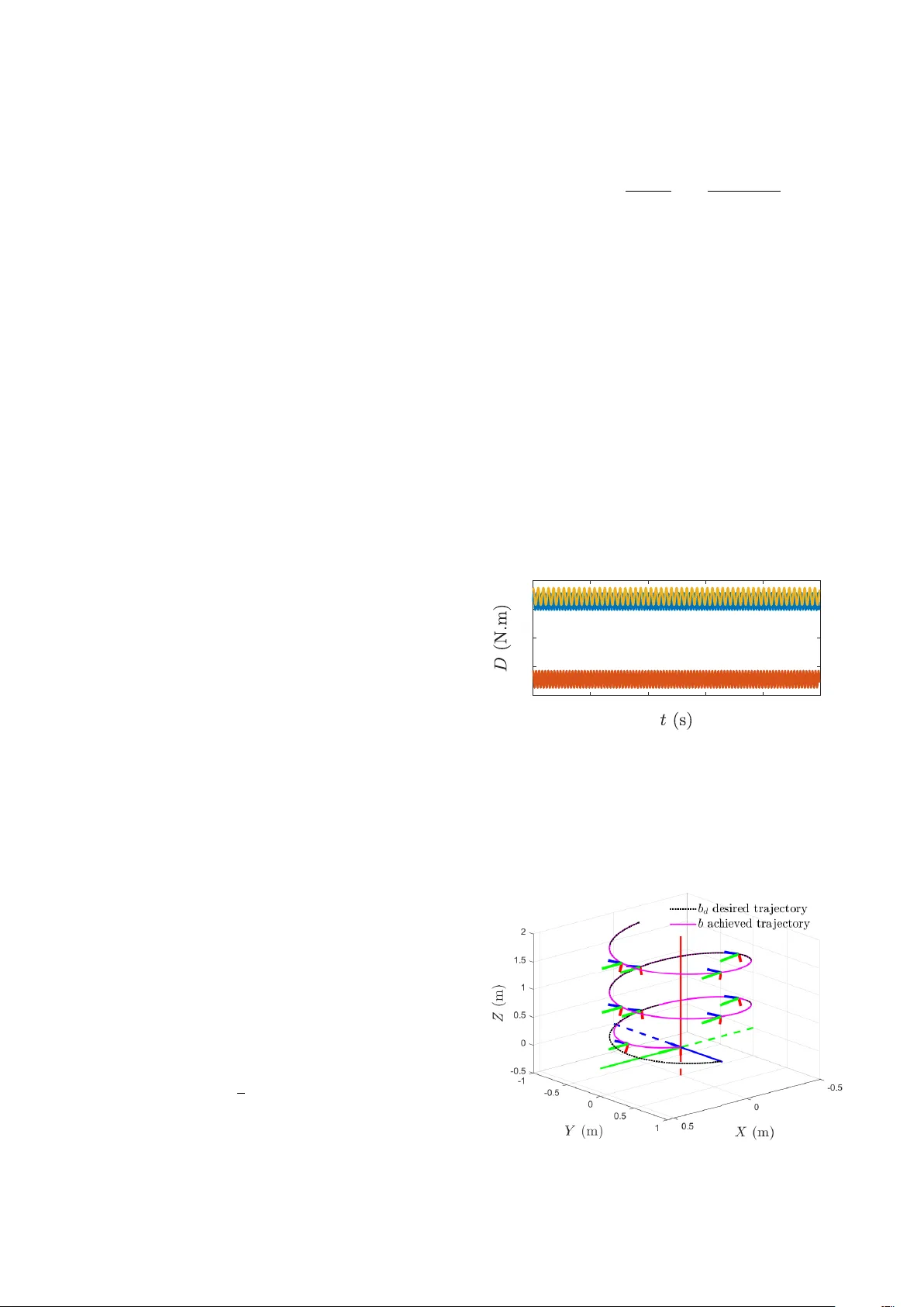
Geometric PID-type attitude tracking contr ol on SO(3) Hossein Eslamiat , Ningshan W ang , Amit K. Sanyal Department of Mechanical and Aerospace Engineering, Syracuse University , Syracuse, NY 13244, USA Abstract This article dev elops and proposes a geometric nonlinear proportional-integral-deriv ative (PID) type tracking control scheme on the Lie group of rigid body rotations, SO(3). Like PD-type attitude tracking control schemes that have been proposed in the past, this PID-type control scheme exhibits almost global asymptotic stability in tracking a desired attitude profile. The stability of this PID-type tracking control scheme is shown using a L yapunov analysis. A numerical simulation study demonstrates the stability of this tracking control scheme, as well as its rob ustness to a disturbance torque. In addition, a numerical comparison study shows the e ff ectiv eness of the proposed integrator term. K e ywor ds: Geometric control, Lie groups, L yapunov stability 1. Introduction Classical PID control schemes are widely used in practice and hav e se veral applications due to their ease of design and tunable properties. PID controllers create a control input based on a tracking error , which is the di ff erence between the actual output and a desired (reference) output. This control input has three terms: one proportional to the error, one proportional to the time inte gral of the error , and another term proportional to the time deriv ative of the error . Using PID feedback has the advantage of eliminating steady state error (using an integral term) and reducing oscillations (using a deriv ativ e term) [1]. In addition, when the mathematical model of a plant is not kno wn and hence analytical design methods cannot be used, PID con- trollers prove to be very useful [2]. The popularity of PID con- trollers can be attributed partly to their good performance in a wide range of operating conditions and partly to their func- tional simplicity [3]. Some PID controllers ha ve been proposed for rigid body attitude tracking by utilizing local coordinates or quaternions, such as the ones in [4, 5, 6, 7], ho we ver , these su ff er from singularities or unwinding [8]. Unwinding occurs when in response to certain initial conditions, a closed loop tra- jectory undergoes a homoclinic-like orbit that initiates near the desired attitude equilibrium. For more details on unwinding, see [9, 10]. Geometric mechanics is the interface for applying geomet- ric control to mechanical systems. This approach results in con- serving features of the configuration space without the need of local coordinates or parameterization. An early work extending classical PD control to mechanical systems e v olving on config- uration manifolds is [11], where PD-type control was used to stabilize a desired configuration. It is worth noting that controls Email addr esses: heslamia@syr.edu (Hossein Eslamiat), nwang16@syr.edu (Ningshan W ang), aksanyal@syr.edu (Amit K. Sanyal) for such systems are defined on the tangent space of the configu- ration manifold. In subsequent years, others ha ve proposed v ar- ious geometric PD-type controllers, such as in [12, 13, 14, 15]. If there is a bounded parameter error or disturbance, a geomet- ric PD controller can guarantee global boundedness of tracking errors, although, they might not con ver ge to zero. By choosing su ffi ciently large PD gains, the errors can be made arbitrarily small. Ho wever this can result in amplifying undesirable noise, saturating actuators, and requiring large control e ff ort. This, alongside the added robustness, motiv ates adding an integrator to a PD type controller . Research on geometric PID-type control includes [16], in which the authors consider control of a mechanical system on a Lie group. They propose an inte gral action, ev olving on the Lie group, to compensate the drift resulting from a constant bias in velocity and torque inputs. Howe ver , they assume a constant time-in variant bias, and only discuss feedback stabilization and not the feedback tracking problem. The work in [17] defines an integral term by putting the deriv ative of integral error equal to the intrinsic gradient of the error function plus a v elocity error term. Howe ver , since the deri vati ve of the integral term is not on the tangent space, the integrator is nonintrinsic. Therefore, the integrator depends on the coordinates chosen for the Lie algebra of the Lie group, unlike the intrinsic PID controller proposed in [18]. A more recent work [19] considers the tracking prob- lem and proposes a PID controller for a rigid body with inter- nal rotors. This builds on the previous PID controller designed in [18], where it is sho wn an intrinsic (geometric) inte gral ac- tion ensures that tracking errors con verge to zero, in response to constant velocity commands. Follo wing up on this prior work, [19] dev elops an intrinsic PID controller on SO(3) for at- titude tracking applications. The proposed PID-type controller and tracking algorithm can work in conjunction with trajectory generation algorithms such as in [20, 21, 22, 23, 24, 25, 26]. A generated trajectory can be considered as the desired trajectory Pr eprint submitted to Systems and Contr ol Letters September 17, 2019 and be tracked by the algorithm presented in this paper . This paper is organized as following. Section 2 formulates the problem by introducing coordinate frames used, reference attitude trajectory and attitude dynamics. Section 3 discusses tracking error kinematics and dynamics. Section 4 proposes the geometric PID controller , along with its stability proof. Section 5 is dedicated to a Lie group variational integrator (LGVI) dis- cretization and numerical v alidation, and comparison with a PD type controller and discussion of disturbance-free case. Finally , section 6 concludes the paper and gives directions for future work. 2. Problem F ormulation The treatment in this paper is general and can be applied to vehicles modeled as rigid bodies, e.g., spacecraft, unmanned underwater vehicles and unmanned aerial v ehicles like quadro- tors. 2.1. Coor dinate frames The two coordinate systems used to define the attitude of a rigid body are inertial and body-fixed coordinates. Attitude of the vehicle is defined as the rotation from body-fixed frame to inertial frame and is denoted R ∈ SO(3). For attitude track- ing, we also define a desired attitude trajectory in time, denoted R d ( t ). In addition, we denote by Ω the angular velocity and Ω d denotes the desired angular velocity . 2.2. Refer ence Attitude Generation The desired attitude trajectory for the rigid body is assumed to be generated and av ailable a priori. As an example for rotor- craft unmanned aerial vehicles (U A Vs) the desired attitude tra- jectory can be generated from the position trajectory , by using the kno wn dynamics model and actuation. Let m and J denote mass and inertia of a rigid body , respectively . The rotational dynamics of the rigid body is giv en by: ˙ R = R Ω × , (1) J ˙ Ω = J Ω × Ω + τ , (2) where τ is the input torque and the cross map:( · ) × : R 3 → SO(3) is giv en by [27]: x × = x 1 x 2 x 3 × = 0 − x 3 x 2 x 3 0 − x 1 − x 2 x 1 0 . 3. T racking err or kinematics and dynamics on TSO(3) The attitude tracking error is defined by [27]: Q = R T d R . (3) T aking the time deri vativ e results in: ˙ Q = ˙ R T d R + R T d ˙ R = ( R d ( Ω d ) × ) T R + R T d R Ω × = R T d R Ω × − ( Ω d ) × R T d R = Q Ω × − ( Ω d ) × Q = Q ( Ω − Q T Ω d ) × = Q ω × , (4) where ω = Ω − Q T Ω d is the angular velocity tracking error . As a result, J ˙ Ω = J d d t ( ω + Q T Ω d ) = J ( ˙ ω + ˙ Q T Ω d + Q T ˙ Ω d ) = J ( ˙ ω + ( Q ω × ) T Ω d + Q T ˙ Ω d ) = J ( ˙ ω + Q T ˙ Ω d − ω × Q T Ω d ) (5) Figure 1: T racking errors Figure (1) shows a schematic of tracking errors for a quadro- tor U A V model, as the di ff erence between the desired trajectory and actual trajectory . In this figure, ˜ b denotes position tracking error and ˜ v denotes translational velocity tracking error , both defined in inertial frame. 4. Main Result Lemma 1 Let h X , Y i denote tr X T Y and e 1 , e 2 , e 3 be unit vectors in x, y, z dir ections, r espectively . Let I denote the 3 × 3 identity matrix and K be: K = k 1 0 0 0 k 2 0 0 0 k 3 wher e k i ar e distinct positive scalars, and define S K ( Q ) as: S K ( Q ) = 3 X i = 1 k i ( Q T e i ) × e i , (6) such that d d t h K , I − Q i = ω T S K ( Q ). Then h K , I − Q i is a Morse function on SO(3) . The proof of Lemma 1 is giv en in [28] and is omitted here for brevity . Theor em 1 Let k P , k D , k I ∈ R + denote pr oportional, derivative and inte gra- tor feedback gains, r espectively , and let S K ( Q ) be defined as in Lemma 1. Let F I ∈ R 3 ' so (3) be the pr oposed inte grator term given by: J ˙ F I = − k p S K ( Q ) − k D ω, F I (0) = 0 . (7) 2 Considering attitude dynamics of a rigid body as in equations (1)-(2), then the following contr ol law: τ = k I F I − k P S K ( Q ) − k D ω + J ( Q T ˙ Ω d − ω × Q T Ω d ) − J Ω × Q T Ω d , (8) leads to asymptotically stable trac king of ( R d , Ω d ) , wher e ( Q , ω ) ar e trac king error s given by (3)-(4). Pr oof Let V : SO(3) × R 3 → R + be a L yapunov candidate gi ven by: V = ¯ V + k p h K , I − Q i , (9) where ¯ V = 1 2 n ( F I − ω ) T J ( F I − ω ) + ω T J ω o . (10) Note that by Lemma 1, h K , I − Q i is a Morse function on SO(3), so is V . By comparing equation (5) and dynamics equation (1) we get: J ˙ ω + J ( Q T ˙ Ω d − ω × Q T Ω d ) = J Ω × Ω + τ , (11) then, J ˙ ω = J Ω × Ω + J ( ω × Q T Ω d − Q T ˙ Ω d ) + τ . (12) As a result, ω T J ˙ ω = ω T [ J Ω × Ω + J ( ω × Q T Ω d − Q T ˙ Ω d ) + τ ] . (13) Consider equation (9), according to Lemma 1, by taking time deriv ative of V we get: ˙ V = ˙ ¯ V + k p ω T S K ( Q ) . (14) T aking time deri vativ e of ¯ V in equation (10) giv es ˙ ¯ V = ( F I − ω ) T J ( ˙ F I − ˙ ω ) + ω T J ˙ ω, (15) where J ˙ ω is as expressed in equation (12), and F I as in equation (7). Consider equation (13), and set: J Ω × Ω + J ( ω × Q T Ω d − Q T ˙ Ω d ) + τ = k I F I + J Ω × ω − k P S K ( Q ) − k D ω. (16) This giv es the control torque as: τ = k I F I − k P S K ( Q ) − k D ω + J ( Q T ˙ Ω d − ω × Q T Ω d ) − J Ω × Q T Ω d . (17) Then as a result ω T J ˙ ω = − k P ω T S K ( Q ) − k D ω T ω + k I ω T F I . (18) Using equation (18), and replacing equation (15) in (14) results in: ˙ V = − k I F T I F I + 2 k I ω T F I − k D ω T ω. (19) By setting k D = k I + k DI where k DI > 0, we get: ˙ V = − k DI ω T ω − k I ( F I − ω ) T ( F I − ω ) ≤ 0 . (20) Considering equations (9) and (20) and e voking the inv ariance- like theorem 8.4 in [29] (which uses Barbalat’ s lemma), we can conclude the following. As t → ∞ , both ω and ( F I − ω ) approach 0. Therefore, as t → ∞ , F I → 0. In addition, we can conclude that as t → ∞ , h K , I − Q i → 0 and hence Q → I . Therefore the tracking errors ( Q , ω ) conv erge to ( I , 0) in an asymptotically stable manner . This means that the pro- posed control law in equation (17) leads to asymptotically sta- ble tracking of the desired attitude trajectory ( R d , Ω d ). 4.1. Robustness to disturbance tor que The stability result of Theorem 1 guarantees asymptotic con- ver gence of tracking errors ( Q , ω ) to ( I , 0) when there is no dis- turbance. If there exist a bounded disturbance torque D , track- ing errors will con ver ge to a bounded neighborhood of ( I , 0). Theorem 2 giv es a specific relation between the size of a neigh- borhood of ( I , 0) and disturbance torque D , to guarantee conv er- gence of tracking errors ( Q , ω ) to that neighborhood of ( I , 0) . Theor em 2 Let D be a disturbance torque that is bounded in norm by a scalar γ , i.e., k D k ≤ γ , acting on the dynamics of the system given by equation (2), as follows: J ˙ Ω = J Ω × Ω + τ + D . (21) Then with the contr ol law given by equation (17), the tracking err ors ( Q , ω ) con ver ge to a neighborhood of ( I , 0) given by N ( I , 0) : = { ( Q , ω ) : k (2 ω − F I ) k γ ≤ k DI k ω k 2 + k I k F I − ω k 2 } , (22) asymptotically in time. Pr oof By considering disturbed dynamics in equation (21) and follow- ing similar steps as in the proof of theorem 1, it can be verified that for the disturbed system ˙ V becomes: ˙ V = − k DI ω T ω − k I ( F I − ω ) T ( F I − ω ) + (2 ω − F I ) T D . (23) The (2 ω − F I ) T D term is upper bounded by (2 ω − F I ) T D ≤ k (2 ω − F I ) k k D k ≤ k (2 ω − F I ) k γ, (24) and hence, ˙ V is upper bounded by ˙ V ≤ − k DI ω T ω − k I ( F I − ω ) T ( F I − ω ) + k (2 ω − F I ) k γ. (25) Therefore, ˙ V ≤ − k DI k ω k 2 − k I k F I − ω k 2 + k (2 ω − F I ) k γ. (26) 3 Consequently , ˙ V is negati ve semi-definite if − k DI k ω k 2 − k I k F I − ω k 2 + k (2 ω − F I ) k γ ≤ 0 , (27) and that is a su ffi cient condition for asymptotic conv ergence of ( Q , ω ) to the neighborhood N ( I , 0) . The size of this neighbor - hood is giv en by (22). For numerical simulations in the next section, we introduce a time-varying disturbance and show how the proposed PID- type controller e ff ectiv ely compensates for disturbance, com- pared to a geometric PD-type controller . In addition, we com- pare our geometric PID-type controller with a classic ”non- geometric” PID controller . 5. Numerical Simulation For simulation purposes, we consider a quadrotor U A V . The complete control of a quadrotor U A V has two loops: the outer loop position control (translational) and the inner loop attitude control (rotational). The attitude should change such that the desired position trajectory is achiev ed. In this paper we are looking at the inner loop of attitude control, and proposing a geometric PID type controller for it. Howe ver , to hav e mean- ingful simulations, we would like to utilize a position controller as well, in conjunction with our proposed attitude controller . Hence for the outer loop of position, we use the translational controller in equation (18) of [30], as giv en below: f = e T 3 R T mge 3 + P ˜ b + L v ( R ν − v d ) − m ˙ v d . (28) T o make meaningful comparisons, we use this outer loop po- sition controller in all the following simulations, while v arying the inner loop attitude controller for our comparison purposes. In addition, a desired attitude trajectory based on the quadrotor U A V’ s position trajectory is considered, and then tracked by the proposed algorithm. The desired position trajectory is a helix; going up in the z direction, as sho wn with a black dotted line in Fig. 3. 5.1. Discr etization by LGVI Discretization of equations of motion is done by utilizing a Lie Group V ariational Integrator (LGVI), which, in contrast to general purpose numerical integrators, preserves the structure of configuration space without parameterization or re-projection. The LGVI scheme used in this work was first proposed in [31]. The time step for discretization is a constant h = t k + 1 − t k . Here ( . ) k denotes a parameter of the system at time step k . The dis- crete equations of motions are: R k + 1 = R k F k , Ω × d k + 1 = 1 h log( R T d k R d k + 1 ) , J Ω k + 1 = F T k J Ω k + h τ k , where F k ≈ exp h Ω × k ∈ SO(3) is ev aluated using Rodrigues’ formula: F k = exp f k × = I + sin k f k k k f k k f × k + 1 − cos k f k k k f k k 2 ( f × k ) 2 , (29) where f k = h Ω k . This guarantees that R k ev olves on SO(3). For more details on discretization using LGVI please refer to [31]. 5.2. Simulation Results The quadrotor model considered in the simulations has the following ph ysical properties: J = d iag (0 . 0820 , 0 . 0845 , 0 . 1377) , m = 4 . 34 kg , (30) and the time step in simulations is h = 0 . 01s. T o demonstrate the performance of the proposed geometric PID-type controller, and show e ff ecti veness of the novel integrator term, we intro- duce a time-v arying disturbance torque to the system with com- ponents shown in Fig. 2, and then compare the results with the geometric PD-type attitude controller of [30]. 0 2 4 6 8 10 -0.3 -0.2 -0.1 0 0.1 Figure 2: Components of disturbance torque D and how they change with time The disturbance sho wn in the abov e figure consists of the sum of constant and sinusoidal terms. The simulations were done using Matlab to encode the LGVI algorithm and the con- trol laws. Figure 3: 3D tracking 4 Figure 3 shows how the position and attitude trajectories con verge to the desired trajectory using the proposed PID-type attitude tracking control in conjunction with the position track- ing controller in equation (28). 0 2 4 6 8 10 0 0.2 0.4 0.6 Figure 4: Position error norm vs T ime Figure 4 shows the magnitude of position tracking error ov er time, and how it con ver ges to zero. 0 2 4 6 8 10 0 0.2 0.4 0.6 0.8 Figure 5: V elocity error norm vs Time 0 2 4 6 8 10 38 40 42 44 Figure 6: Thrust vs T ime Figure 5 shows associated velocity tracking error magnitude con verging asymptotically to zero as expected. Figure 6 shows the thrust magnitude required to track the desired position tra- jectory . 0 2 4 6 8 10 -1.5 -1 -0.5 0 0.5 1 1.5 Figure 7: Angular velocity tracking error dynamics vs time Figure 7 sho ws components of the angular velocity track- ing error , ω , and that the y con verge asymptotically to zero with time. 0 2 4 6 8 10 0 0.1 0.2 0.3 0.4 0.5 Figure 8: Attitude tracking error vs time Figure 8 shows the asymptotic con vergence of the attitude tracking error with time. 0 2 4 6 8 10 0 2 4 6 8 10 Figure 9: Magnitude of Control torque vs time Figure 9 shows the magnitude of the proposed control torque ov er time. 5.3. E ff ectiveness of the inte grator term E ff ectiv eness of the integrator term in the proposed geomet- ric PID-type attitude control is shown by the follo wing compar - ison: Under the same disturbance torque of Fig. 2, we use the ge- ometric PD-type attitude controller of [30] to track the same trajectory , and compare the results with our proposed geomet- ric PID-type attitude controller . 5 0 2 4 6 8 10 -1.5 -1 -0.5 0 0.5 1 1.5 Figure 10: Angular velocity tracking error dynamics vs time for PD-type con- troller of [30] Figure 10 sho ws that for the PD-type controller , compo- nents of ω do not con verge to zero but oscillate with noticeable amplitudes about it. On comparing this figure with Fig. 7, we see that the geometric PID-type controller shows significantly better performance. 0 2 4 6 8 10 0 2 4 6 8 10 Figure 11: Magnitude of Control torque vs time for PD-type controller of [30] Figure 11 shows rapid oscillations in control that will likely not be realizable by , and therefore should not be implemented on, a quadrotor UA V . Comparing Fig. 9 with Fig. 11, the geometric PID-type controller shows remarkably better perfor- mance with negligible oscillations. In addition, Figure 11 shows the large magnitude of the required control torque gi ven by the geometric PD-type controller . Comparing Fig. 9 with the Fig. 11, we can see much less required control e ff ort was needed by the geometric PID-type controller compared to the geometric PD-type controller . 0 2 4 6 8 10 0 0.1 0.2 0.3 0.4 0.5 For PD case For PID case Figure 12: Norm of attitude tracking error for the proposed PID-type controller and the PD-type controller in [30] Figure 12 shows norm of the attitude tracking error for both PD and PID-type controllers. The PID-type controller sho ws this error to be decreasingly more smoothly and with lesser os- cillations than the PD-type controller . Overall, the comparison in this subsection shows that the proposed PID-type controller has significant adv antages over a PD-type controller in steady state performance as well as distur- bance attenuation. It tracks the same maneuvering attitude tra- jectory better while requiring significantly less overall control e ff ort under the influence of a time-varying disturbance torque. 5.4. Comparing with zer o disturbance case Another interesting observation can be made by comparing the performance of the proposed PID-type controller under in- fluence of disturbance, which was presented in section 5.2, with its performance when there is no disturbance ( D = 0), while tracking the same desired trajectory . If disturbance is zero, then the proposed PID controller, gives the following results in our numerical simulation. 0 2 4 6 8 10 -1.5 -1 -0.5 0 0.5 1 1.5 Figure 13: Angular velocity tracking error dynamics vs time for D = 0 Figure 13 shows components of the angular velocity track- ing errors over time and that they con verge asymptotically to zero. This case ( D = 0) can be thought of as an ideal case, and by comparing Fig. 7 with the above figure, we can see how little the performance of the PID-type controller changes under the influence of disturbance. The time plots in Fig. 7 show a sim- ilar tracking profile to the ideal case of zero disturbance (Fig. 13). 0 2 4 6 8 10 0 2 4 6 8 10 Figure 14: Magnitude of Control torque vs time for D = 0 Figure 14 sho ws the control torque magnitude, as giv en by the proposed PID-type controller when there is no disturbance, i.e., D = 0. Again considering this case as an ideal case, we see how well the PID-type controller performs in the presence of disturbance: the profile in Fig. 9 is similar (with minor os- cillations) to that of Fig. 14. 6 T o summarize, in this subsection we compared the perfor- mance of the PID-type attitude tracking controller for two sit- uations; one when there is no disturbance torque (ideal case) and the other in the presence of a disturbance torque. W e ob- served that under a disturbance torque the proposed controller performs well, and results in similar (but slightly de graded) per- formance as in the ideal case of zero disturbance. 5.5. Comparing with a classic non-geometric PID contr oller In this part, we utilize a classic non-geometric PID con- troller gi ven in [32] as the attitude controller . Following are the results of this simulation. As can be seen from the div erging errors, this non-geometric PID does not perform well with our LGVI dynamics engine. 0 2 4 6 8 10 0 50 100 150 200 250 Figure 15: Position error norm vs T ime for non-geometric PID 0 2 4 6 8 10 0 50 100 150 200 Figure 16: V elocity error norm vs Time for non-geometric PID In Figures 15 and 16 diver ging position error norm and ve- locity error norm are shown, respecti vely . 0 2 4 6 8 10 -4 -3 -2 -1 0 1 10 6 Figure 17: Angular velocity tracking error dynamics for non-geometric PID 0 2 4 6 8 10 0 1 2 3 Figure 18: Attitude tracking error for non-geometric PID Figures 17 and 18 show attitude and angular velocity track- ing errors and how the y perform. From this simulation it can be inferred that the geometric PID controller performs better with the LGVI, compared to a classic non-geometric PID controller that can not enforce the er- rors to zero in conjunction with the position controller in equa- tion (28). 6. Conclusion and Future W ork In this work a geometric PID-type attitude tracking control scheme w as de veloped and its stability w as sho wn theoretically using L yapunov analysis on the state space of rigid body atti- tude motions. Analysis of robustness to disturbance torque w as presented. Numerical simulations confirmed the performance of the attitude controller, ev en in the presence of an oscillat- ing disturbance torque, in comparison with a geometric PD- type attitude controller, and a non-geometric PID controller . In the near future, we plan to implement this attitude control scheme in software-in-the-loop (SITL) simulations using the open source PX4 software for a particular quadrotor U A V con- figuration. This will be followed by hardware implementation on the corresponding U A V platform. Acknowledgements The authors acknowledge support from the National Sci- ence Foundation a ward CISE 1739748. References References [1] G. F . Franklin, D. J. Powell, and A. Emami-Naeini, F eedback Contr ol of Dynamic Systems , 4th ed. Upper Saddle Ri ver, NJ, USA: Prentice Hall PTR, 2001. [2] K. Ogata, Modern Contr ol Engineering , ser . Instrumentation and controls series. Prentice Hall, 2010. [Online]. A v ailable: https: // books.google.com / books?id = W u5GpNAelzkC [3] R. Dorf and R. Bishop, Modern Control Systems . Pearson Prentice Hall, 2011. [Online]. A vailable: https: // books.google.com / books?id = lerbSAAA CAAJ [4] J. T . . W en and K. Kreutz-Delgado, “The attitude control problem, ” IEEE T ransactions on Automatic Contr ol , vol. 36, no. 10, pp. 1148–1162, Oct 1991. [5] C. Li, K. L. T eo, B. Li, and G. Ma, “ A constrained optimal PID-like controller design for spacecraft attitude stabilization, ” Acta Astr onautica , vol. 74, pp. 131 – 140, 2012. [Online]. A vailable: http: // www .sciencedirect.com / science / article / pii / S009457651100381X 7 [6] J. Su and K.-Y . Cai, “Globally stabilizing proportional-integral-deri vati ve control laws for rigid-body attitude tracking, ” Journal of Guidance, Con- tr ol, and Dynamics , vol. 34, pp. 1260–1264, 07 2011. [7] K. Subbarao and M. Akella, “Di ff erentiator -free nonlinear proportional- integral controllers for rigid-body attitude stabilization, ” J ournal of Guid- ance Contr ol and Dynamics - J GUID CONTR OL DYN AM , vol. 27, pp. 1092–1096, 11 2004. [8] N. A. Chaturv edi, A. K. San yal, and N. H. McClamroch, “Rigid-body attitude control, ” IEEE Contr ol Systems Magazine , vol. 31, no. 3, pp. 30– 51, June 2011. [9] S. P . Bhat and D. S. Bernstein, “ A topological obstruction to continuous global stabilization of rotational motion and the unwinding phenomenon, ” Systems and Control Letter s , vol. 39, no. 1, pp. 63 – 70, 2000. [Online]. A vailable: http: // www .sciencedirect.com / science / article / pii / S0167691199000900 [10] C. G. Mayhew , R. G. Sanfelice, and A. R. T eel, “On path-lifting mecha- nisms and unwinding in quaternion-based attitude control, ” IEEE Tr ans- actions on Automatic Contr ol , vol. 58, no. 5, pp. 1179–1191, May 2013. [11] D. E. K oditschek, “The application of total energy as a Lyapunov function for mechanical control systems, ” February 1989. [12] F . Bullo and R. M. Murray , “Proportional Deri vati ve (PD) control on the euclidean group, ” in pr oceedings of 3rd European Control Conference , 1995. [13] T . Lee, M. Leok, and N. H. McClamroch, “Geometric tracking control of a quadrotor UA V on SE(3), ” in 49th IEEE Confer ence on Decision and Contr ol (CDC) , Dec 2010, pp. 5420–5425. [14] D. H. S. Maithripala, J. M. Berg, and W . P . Dayawansa, “ Almost-global tracking of simple mechanical systems on a general class of Lie groups, ” IEEE T ransactions on Automatic Contr ol , v ol. 51, no. 2, pp. 216–225, Feb 2006. [15] R. Hamrah, R. R. W arier, and A. K. Sanyal, “Discrete-time stable tracking control of underactuated rigid body systems on SE(3), ” in 2018 IEEE Confer ence on Decision and Contr ol (CDC) , Dec 2018, pp. 2932–2937. [16] Z. Zhang, A. Sarlette, and Z. Ling, “Integral control on Lie groups, ” Sys- tems and Contr ol Letters , v ol. 80, pp. 9 – 15, 2015. [17] F . Goodarzi, D. Lee, and T . Lee, “Geometric nonlinear PID control of a quadrotor U A V on SE(3), ” 07 2013, pp. 3845–3850. [18] D. Maithripala and J. M. Berg, “ An intrinsic PID controller for mechanical systems on Lie groups, ” Automatica , v ol. 54, pp. 189 – 200, 2015. [Online]. A vailable: http: // www .sciencedirect.com / science / article / pii / S0005109815000060 [19] A. Nayak, R. N. Bana var , and D. H. S. Maithripala, “ Almost-global track- ing for a rigid body with internal rotors, ” European J ournal of Control , vol. 42, pp. 59 – 66, 2018. [20] M. W . Mueller, M. Hehn, and R. D’Andrea, “ A computationally e ffi cient motion primitive for quadrocopter trajectory generation, ” IEEE T ransac- tions on Robotics , vol. 31, no. 6, pp. 1294–1310, Dec 2015. [21] Y . Bouktir , M. Haddad, and T . Chettibi, “Trajectory planning for a quadrotor helicopter, ” in 2008 16th Mediterranean Conference on Con- tr ol and Automation , June 2008, pp. 1258–1263. [22] M. Cutler and J. How , Actuator Constrained T rajectory Generation and Contr ol for V ariable-Pitch Quadr otors . American Institute of Aeronautics and Astronautics, 2017 / 03 / 19 2012. [Online]. A vailable: http: // dx.doi.org / 10.2514 / 6.2012- 4777 [23] H. Eslamiat, Y . Li, N. W ang, A. K. Sanyal, and Q. Qiu, “ Autonomous waypoint planning, optimal trajectory generation and nonlinear tracking control for multi-rotor uavs, ” in 2019 18th European Contr ol Conference (ECC) , June 2019, pp. 2695–2700. [24] D. Mellinger and V . K umar , “Minimum snap trajectory generation and control for quadrotors, ” in Robotics and A utomation (ICRA), 2011 IEEE International Confer ence on . IEEE, 2011, pp. 2520–2525. [25] B. T . Ingersoll, J. K. Ingersoll, P . DeFranco, and A. Ning, ser . AIAA A VIA TION Forum. American Institute of Aeronautics and Astronautics, Jun 2016, ch. UA V Path-Planning using Bezier Curves and a Receding Horizon Approach, 0. [Online]. A vailable: https: // doi.org / 10.2514 / 6.2016- 3675 [26] Y .Li, H.Eslamiat, N.W ang, Z.Zhao, A. K. Sanyal, and Q.Qiu, “ Au- tonomous waypoints planning and trajectory generation for multi-rotor U A Vs, ” in Pr oceedings of Design Automation for CPS and IoT , 2019. [27] A. Sanyal, N. Nordkvist, and M. Chyba, “ An almost global tracking con- trol scheme for maneuverable autonomous vehicles and its discretiza- tion, ” IEEE T ransactions on Automatic Contr ol , vol. 56, no. 2, pp. 457– 462, Feb 2011. [28] M. Izadi and A. K. San yal, “Rigid body attitude estimation based on the Lagrange-dAlembert principle, ” Automatica , vol. 50, no. 10, pp. 2570 – 2577, 2014. [29] H. K. Khalil, Nonlinear systems . Prentice Hall, 2002. [30] S. P . V iswanathan, A. K. Sanyal, and E. Samiei, “Integrated guidance and feedback control of underactuated robotics system in SE(3), ” Journal of Intelligent and Robotic Systems , vol. 89, no. 1, pp. 251–263, Jan 2018. [Online]. A vailable: https: // doi.org / 10.1007 / s10846- 017- 0547- 0 [31] N. Nordkvist and A. K. Sanyal, “ A Lie group variational integrator for rigid body motion in SE(3) with applications to underwater vehicle dy- namics, ” in 49th IEEE Confer ence on Decision and Control (CDC) , Dec 2010, pp. 5414–5419. [32] P . Pounds, R. Mahony , and P . Corke, “Modelling and control of a large quadrotor robot, ” Contr ol Engineering Pr actice , v ol. 18, no. 7, pp. 691– 699, 2010. 8
Original Paper
Loading high-quality paper...
Comments & Academic Discussion
Loading comments...
Leave a Comment