Long range battery-less PV-powered RFID tag sensors
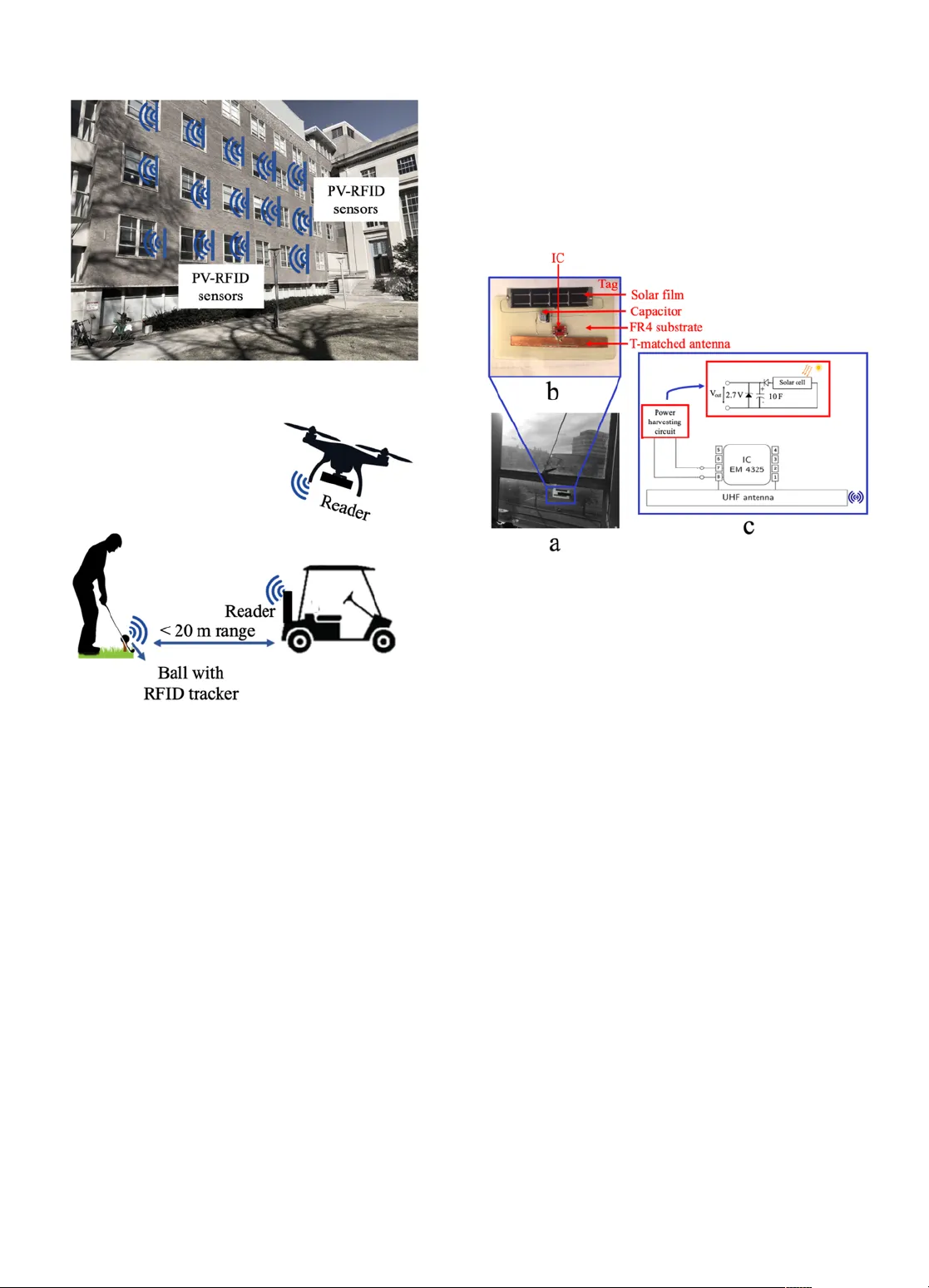
Communication range in passive Radio-Frequency Identification (RFID) front-end devices is a critical barrier in the real-world implementation of this low-cost technology. Purely passive RFID tags power up by harvesting the limited RF energy transmitt…
Authors: Sai Nithin R. Kantareddy, Ian Mathews, Rahul Bhattacharyya
1 Long range battery - less PV - powered RFID tag sensors Sai Nithin R. Kanta r eddy , Ian Mathews, Rahul Bhattacharyya, Ian Marius Peters, T onio Buonassisi, and Sanjay E. Sarma Abstract — Communication range in passive Radio - Frequency Identification (RFID) front - end devices is a critical barrier in the real - world implementation of this low - cost technology . Purely passive RFID tags power up by harvesting the limited RF energy transmitted by the interrogator , and communicate by backscattering the incident signal. This mode of comm unication kee ps manufactur ing costs bel ow a few cents per tag, but the limited powe r availabl e at the tag unde rmines long - range deploymen t. In this pa per , we present an approach to use Photovoltaics (PV) to augment the available energy at the tag to improve read range and sensing capabilities. We provide this extra - energy to the RFID integrated circuit (IC) using m inimum additional electronics yet enabling persistent sensor - data acquisition. Current and emerging thin - film PV technologies have significant po tential for b eing very low - cost, hence eliminating the barrier for implemen tation and making of PV - RFID wireless sensors. We reduce the long - range PV - RFID i dea to pra ctice by creating functional prototypes of i) a wireless building environment sensor to monitor temperature, and ii) an em bedded tracker to find lo st go lf balls . The read rang e o f PV - RFID is enhanced 8 times compared to conventional passive devices. In ad dition, the PV - RFID tags persistently transmit large volumes of sensor data (>0.14 million measurement s per day) without using ba tteries. For communication range and energy persis tence, we observe good agre ement between calculated estimates and experimenta l results . We hav e a lso id en tifi ed av enu es fo r f utu re res ear ch to de vel op lo w - cost PV - RFID devices for wir eless sensing in the midst of the other competitive wireless technologie s such as Bluet ooth, Zigbee, Long Range (LoRa) back scatter etc . Index T er ms — B attery - less S ensors, Energy Harvesting, Int ernet of Things, Photov oltaics, RFID, Wireless Sensing —————————— u —————————— 1 I NTRODUCTION he Inter net of Things (IoT) market is projected to initiate growth of wireless sensor production. According to McKinsey, the over all annua l value of consu mer and Industrial IoT technologies will reach around $3.9 to $11.1 trillion b y 2025 [1] . This will be a result of massive sensor deployment and real - time data acquisition for control, optimization and data - driven predictions in various applications. Around 67 billion IoT devices across industry segments are expected to be deployed on the network by 2025 creating a massive demand for sensor infrastructure [2] . Ultra - High Frequency (UHF) Radiof requency Identific ation (RFID) technology is well positioned to provi de the needed low - cost sensors [3] , especially where pervasive object tracking or wir eless sensing is required. Moreover, industries that have already invested in UHF RFID hardware for inventory tracking can economically leverage the ex isting infrastructure for other functionalities such as sensing and inventory quality mon itoring. The rea der - tag communication protocol is standardized, facilitating data interoperability in sensor networks [4] . There are billions of RFID tags already in circulation that work on this globally standard Gen2 air - interface proto col in Industrial, Scientific and Me dical (ISM) frequency ban ds . As a result, RFID technology has become popular for inexpensive, wireless object identification across a broad array of industry supply chains over the last decade [5] . RFID’s abili ty to ident ify, trace and trac k information usi ng easily deployable tags is now enabling applications beyond supply chain management, in new areas of sensing [6] – [8] , actuation [9] , and even user interaction [10] . RFID tags are used as st andalone identifiers and sensors, as well as RF - front end for other off - the - shelf commercially available sensors [11], [12] . RFID t ags ar e clas sified into passive, semi - passive and active tags. The integrated circuit (IC) on the passive tags i s powered by harvesting the limited RF energy transmitted by the interrogat or/reader, and communicate by backscatter ing the incident signal. Although this implementation reduces the manufactur ing c ost by keepi ng IC costs low, limit ed powe r available at the tag limits the long - range communication and power hungry sensing capabilit ies. In semi - passive t ags, an external battery powers t he IC without consuming the incident RF energy , thereby making more RF energy dispensable for backscat tering over a long distance [13] . In ———————————————— • Sai Nithin R. Kant areddy is with the Department of Mechanical Enginee r- ing, Massachusetts In stitute of T echnology , MA - 02139. E - mail: ni- thin@mit.edu • Ian Mathews is with the MIT PV La b and the Department of Mechanical Engineering, Massachus etts Institute of T echnology , MA - 02139. E - mail: imathews@mit.edu • Rah ul Bhattachar yya is with Auto - ID Labs and the Department of Me- chanical Engineering, Massachusetts Institute of T echnology, MA - 02139. E- mail: rahul_b@mit.edu • Ian Marius Peters is with the MIT PV L ab and the Department of Mechan- ical Engineering, Ma ssachuset ts Institute of T echnology , MA - 02139. E - mail: impe ters@mit.e du • To n i o B u o n a s s i s i i s w i t h t h e M I T P V L a b a n d t h e D e p a r t m e n t o f M e c h a n i - cal Engineering, Massachusetts Institute of T echnology, MA - 02139. E - mail: buon assisi@mit .edu • Sanjay E. Sarma i s with Auto - ID Labs and the Department of Mechanica l Engineering, Massachus etts Institute of T echnology , MA - 02139. E - mail: sesarma@mit.edu T 2 IEEE INTERNET OF THIN GS JOURNAL, MANUSCRIPT ID active RFID, a battery - powered on - board trans mitter broadcasts the RF signal without requiring any energy from the reader. Howev er, battery - assisted wireless devices, including RFID tags, pose several design constraints such as limited lifecycle, scheduled replacement cycles, cost, size, weight, sh ape, lithiu m waste, etc. [14] – [16] . A s olution to this pro blem i s t o us e P hotovoltaics (PV) to partially or f ully reduce the dependence on batteries. There are also other non - PV ambient energy harvesting systems to power wire less - sensors [17] – [19] . However, these technique s require close proximity to the corresponding energy sources such as human body, power lines or tempe rature gradients. Other emerg ing techniq ues such as o ffloading power packets from licensed communication bands for wireless energy harvesting for IoT will require further research in high efficiency RF - DC ener gy converters [20] . With the widespread availabi lity of light as an e nergy source both indoors and outdoors, photovoltaics are a convenient option to serve the energy needs of wireless sensors [21] – [24] . Therefore, we pr opose PV - RFI D sensor plat form tha t uses harvested energy from PV to powerup the IC and offers extended range compared to conventional passive RFID. Figure 1 is an illustr ati on of flexible PV - RFID sensor communicating with RFID reader over 10 - meter distance. Available literature shows t he use of PV - powered RFID concept on multi - port tags (2 ICs) in [25] , Intel’s Wirele ss Identification and Sensing Platform (WISP) in [26] , and Ultra - Wideb and ( UWB) t ags i n [27] . Although these studies show an i ncrease in the read range, none of them present a persistently transmitted sensor measurement over a long time duration. Moreover, using two ICs in the multi - port tags doubles the cost compared to a si ngle t ag. PV - powered Intel’s WISP is a relatively power - hungry device, which requires both RF and PV energy harvesting. On the other hand, UWB tag protocol is not standardized, and has limited commercial use. Therefore, there is a need to show PV - powered long - range wireless sensors capable of transmitting high - volume sensor m easurements using an established communication protocol like UHF RFID. Previously, the MIT PV L ab designed and developed a solar - powered GPS tracker with cellular communication for real - world application , and demonstrated the trac ker’s performance on Singapore roads [28] . We also suggested how an adaptive power syst em for IoT sensors can reduce the battery requirement by 90% [2 9] . Extending such analysis to RFID wo uld unl ock id eas f or ble nding e merging PV technologies with established low - cost wireless technology. In this paper, we show how a PV - RFID e nvironment sen sing tag that persistently measures temperature over a day is designed. We also show how a PV - RFID tag can be conformally embedded int o objects such as golf balls for wireless tracking. Fut ure data - driven IoT technologies rely on mass deployable low - cost wireless sensors that ar e capable of transmitting continuous sensor data. Ach ieving this hig h- volume data acquisition yet keeping the costs low is a technical challenge. We pro pose a simple device architecture for PV - RFID with/without intermediate energy storage to lower the costs. We reduce the idea to practice by creating functional prototypes and test the devices for read range and sensed data. In Section 2 , we describe the design considerations and strategies to integrate R FID and PV into a single system. In Section 3 , we discuss the results and inferences from testing the functional prototype s. Conclusions and potential future work are presented in Section 4. 2 DESIGN In this section, first , components comprising a RFID system and the limitations arising from the power deficit are discussed. Next, two applications for the PV - RFID are discussed along with the design details of the prototypes. Later, how photovoltaics are suitable to fill the power gap in RFID is described. 2.1 RFID T ag, Range li mitation and Power - gap The tag and the r eader are the two main physical components of a RFID system. The r eader wirelessly interrogates the tags at speeds up to 1,000 tags/sec (theoretical rate) [30] ,and delivers the tag - data t o the user. The tag itself is a simple impedance - matched antenna conne cted across an IC that processes tag’s RF backscattering function by switching between the two impedance s tates (low and high) as a way of modulating the signal. The working princi ple of a UHF RFI D setup is described in the additional information section. Maximum power transmitted by the reader is constrained by the Federal Communications Commission (FCC) (or similar regional organizations) at 1 W (30 dBm), assu ming an antenna with maximum of 6 dB i gain. Only a fraction of this transmitted RF po wer i s rec eived at the IC after path losses and polarization mismatches . According to F riis electroma gnetic transmi ssion equation, the read range is proportional to the square root of the transmission coefficient [31] . Transmission coefficient is the measure of ho w well the ante nna’s impedance matches with the IC’s impedance. Transmission coefficient is affec ted when t he tag designed for free - space environment is attached to an object with diele ctric backgr ound. Lossy dielectri c materials such as concrete walls, human body and water significantly affect the transmission coefficient (impedance matching ) and the resulting read range. One way to solve this problem is b y designing a well - matched ant enna speci fic to th e background Figure 1 : Schematic i llustration of a PV - RFID sensor KANTAREDDY, S.N.R. ET AL.: LONG RANGE BATTERY -L ESS PV - POWERED RFID TAG SENSORS 3 dielectric , and an alternate approach is to use robust tag detection schemes as outlined in [32], [33] . If the RF power available at the IC is greater than the minimum po wer requ ired to power - up the IC (called the IC’s sensitivity), the modulated signal is backscat tered, and the reader can receive the tag data. Some of the ICs, such as EM 4325 by EM Microelectronics, can function in dual modes, i.e., in both purely - passive and semi - passive modes. In semi - passive modes, this IC can take power from an external source such as PV cell. As a result, more of the RF energy is available for backscattering, which increases the read range. This extra - power from solar cell also enables continuous sensor measurement s to be t aken and t ransmitted to the r eader. Read range i s compared for PV - RFID a nd passive RFID tags using Frii’s transmission equation for free - space (described in the additional information section). Mathemati cally, t he passiv e UHF tag re ad range pe rformance is determined by the radia tive forward link given b y ! "# $ % &' ( )*+ ( ,-*.-, /0 1 2 3 4 2 /0 3 5 . [1] Therefore, 6 $ 7 ! 89 : ;<= : >?<@?> 5 ! "# 3 A B CD $ EFGHIJGI 3 A K % LM % NO , [2] w here P IC : power received at the IC, P TX : power transmitted by the reader, d : range or distance between the reader and the IC, d Passive , d PV - RFID : range in pass ive and PV - RFID cases, λ : wavelength o f the RF si gnal, G tag , G reader : gain of tag - antenna and reader - antennas and τ : transmis sion coefficient. Tag can backscatter i f the power received at the I C ( P IC ) is greater than the IC’s sens itivity. Today, many passive RFID ICs offer sensitivities around - 21 dBm. In PV - RFID, we used EM 4325 IC, which offer s - 31 dBm [38] in the semi - passive mode (when externa l powe r is suppl ied). The 10 dBm gain in the sensitivity by going from passive to semi - passive (such as PV - RFID) contri butes t o the extr a range. Figure 2 plots the estimated range (d) using the above equation s with the conditions set as ! "# $ A P QR A 6ST fo r passive and ! "# $ AP UR A 6ST for PV - RFID cases ass uming 5 $ VWX and overall gain ( : ;<= : >?<@?> Y $ VWX at 915 MHz. 6 Z<[[\]? $ EFGHIJGI 3 A K % LM ^_ `2Wa [3] 6 Zb c de"f $ EFGHIJGI 3 A K % LM ^_ `gWa [4] Theoretically, ranges between 40 and 50 m ar e poss ible with PV - RFID tags, which is signific antly more t han th e 10 m read range achievable by traditional passive tags (see Figure 2 ). Achieving any higher read ranges requires improvements in the reader and t ag sensitivities. State - of - the - art reader s’ receive sensitivity is limited to - 80 dBm, therefore, as the reader and tag separation is increased, after a distance, backscattered signal strength is lower than readers ’ sensitivity. However, the practical read range wil l be lower due to many factors including antenna gai n, antenna - IC impedance match, reader receive sensitivity, temperature, multi - path interference, cont act losses, and background dielectric impedance. With this potential increase in range, one can even monitor the footprint of an Airbus A 380’s wing (~40 m) with a single reader reducing the RFID infrastr ucture (cable s, readers, antennas, mount s, etc.) costs. 2.2 Applications We design P V - RFID devices for two cas es whi ch b enefit from the extra - power at the t ags: a s imple att achable bui lding environment sensor to measure window’s temperature and an embedded tracker to find the lost golf balls. Figure 3 (a) is an illustration of these a pplications where 10 - 100’s of battery - less sensors create a building environment sensing netwo rk and RFID augmented golf fie ld. Every opening in the building such as windows, vent s, or exhaust s can be augmented with PV - RFID tags to moni tor environme ntal parameters such as air inflow, temperature, humidity, etc. This real - time sensor data is useful to develop modern data - driven models, for example, models to ru n o ptimized and e nergy effi cient air - conditioning systems. Figure 3 (b) shows an illustratio n of RFID augmented golf field, which is similar to t he commercial Topgol f arenas [34] . Increase in read range due to PV - RFID decrea ses the number of readers and antennas r equired to cover the entire area of a golf field. Additionally, the ext ra - power can be used to power the embedded electronics to inform analytics if the player wants to know the bal l spin using embedded accelerometers to analyze player’s performance in the f uture. Figure 2 : Comparison of read range between passive and PV - RFID tags. Note: FCC assumes an an tenna with 6 dB i gain 4 IEEE INTERNET OF THIN GS JOURNAL, MANUSCRIPT ID 2.2.1 Buil ding environment sensor The sen sor cons ists of an antenna T - matche d [35] to the EM4325 IC contai ning an on - board temperature s ensor. An amorphous silicon (a - Si) solar cell is used to augm ent the power at the IC, which increases the range and capability to transmit continuous temperature measurem ents. A functioning prototype in use, attached to an MIT building’s window, is shown in Figure 4 (a) - (b). As shown in the device’s circuit schematic in Figure 4 (c), a 2.7 V Zener diode is connected across the 10 F capacitor to prevent overcharging beyond its rated capacity. Another diod e is used in s eries with the solar cell to prevent backflow of the current when the output voltage of the solar cell is lower than the capacitor’s terminal voltage. All components are assembled on an FR4 substrate with velcro backing in a form factor easy to attach to window panes , building walls or other objects. Two prototype vari ations are made, one with a larger capacitor size (10 F) and the other with smaller capacitor size (1 mF), to show different persistent levels in operation. Large energy backup i n the former variant comes at the cost of expensive super cap and larger footprint of the product. Addi tionally, different types capacitors have different service times before the capacitance changes significantly from its rated value. Ceramic capacitors t end to have l onger service ti mes in the order of few year. Therefore, in real - world implementation, th e des igner has t o car efully pick the capacitor type and size based on the cost, required output voltage, service time, required backup and product aesthet ics . 2.2.2 Embedded tracker PV - RFID tags are fl exible and easy to embed insid e objects such as a golf ball to create embeddable tags that require no frequent maintenance. We can set up 100 - 1000s of nodes permanently with minimum human inter vention, for example, when sensors are located in hard to reach places such as the inside of sports balls, equipment, building walls , roads, etc. We demonstrate this concept of embedding PV - RFID tags , by developing an embedded tracker to find los t gol f balls from a few meters distance. Embedding PV - RFID is challenging as the mass and s urface topography of the golf b all have a spe cific function that restricts the shape, size as well as the number of embeddable electronics. In an earlier paper [36] , we proposed a conformal 3D antenna design to reduce the cost of manufactur ing tracker - embedded golf balls. With the conformal antenna placed between the inner core and the outer shell, these smart - golf balls can be manufactured with minimum cha nges to the existing manufactu ring proc ess. However, the r ange of the purel y passive golf balls is aroun d 1 m. Wit h a functiona l prot otype, we sh ow how using PV - RFID increases the tracking range to above 10 m. The prototype (see Figure 5 (a) - (b)) consists an embedded tracker and a flexible solar cell wrapped around the inner core to be conformal to existing design. Device’s circuit schematic in Fi gure 5 (c) shows a solar cell directly connected to the terminals of the IC. Since an opaque golf ball does not allow the solar cell to work, we repl aced the standard white ou ter shell with a 3D printed transparent material with transmittance (a) (b) Figure 4 : Prototypes of a buildi ng temperature sensor: (a) sensor attached to a window, (b) components placeme nt, and (c) schematic of electronic circuit Figure 3 : Illustration p otential applications: buil ding envi- ronment sensor (a ); object trac ker for outdoor sports (b). KANTAREDDY, S.N.R. ET AL.: LONG RANGE BATTERY -L ESS PV - POWERED RFID TAG SENSORS 5 value of around 0.8. The solar cell can harvest the light reaching thro ugh the transparent layer and powerup the IC . 2.3 Photov oltaics to fil l the power gap Designing a PV - RFID tag involves select ion of appropriate cell area, capacitor size, antenna geometry and a dielectric substrate. Solar cell area and the capacitor size affects how much energy is ava ilable at the ta g an d how l ong t he t ag can persist in the absence of ambient light. Antenna geometry and substrate’s material should be de signed so as to match the impedance of the chip for maximum backscatterin g of RF energy. We also looked at what percentage of the time the device can per sistently operate taking into account the year - round average insolation at the location and different commercially available capacitor sizes. To achieve a 100% availability, the required minimum capacitor size is on the order of 1 – 10 F (refer additional information section). However, the larg e capac ities affect the charging time, a nd with it the required cell area. Additionally, charge stored in a capacitor self - dissipates due to the leakage currents which vary from as low as 1 µ A to above 50 µ A. For a reasonable charging time of few minutes with the 10 F super capacitor, we select a PV module of 12 cm 2 area. We also looked at how the ter minal vo ltage i n the c a- pacitor changes over few cycles. Figure 6 shows three possi- ble phases occurring during the operation of the PV - RFI D system over a 72 hr duration: directly powered by solar cell, powered by the energy stored in the capacitor, and a blackout phase with no sufficient energy. For example, the device re- quires ~1.5 V and ~3.0 V of threshol d voltage for read/write and EEPROM operations, respectively. W e execute read/write commands to acquire the sensor - data from the PV - RFID tag, therefore, the IC consumes ~ 1 0 µ A at 1.5 V [37] . Stored e n ergy is limited to 2.7 V to prevent overchargi ng of the cap acitor. This results in a sa wtooth w aveform with sh arp charging times for the voltage across the IC as shown i n the figure. At time = 0, capacitor has no charge, therefore, voltage across the IC is zero. Then the capacitor steeply charges to the maximum volt age of 2.7 V due to the ener gy from the solar cell. When the ambient light is available, the device is directly powered by the s olar cell, as a result, the capacitor is kept fully charged and the device still operates. In the next phase, when the solar cell’s outp ut vol tage drops below the capaci- tor’s voltage, the device is then powered by the capacitor until the voltage drops below 1.5 V. In the third phase, the capaci- tor’s terminal voltage is not sufficient to powerup the IC, therefore, the extra - range is lost until the next ambient light phase. Furthe r analysi s on the availabilit y of the device and the effect of discharge cu rrents can be found ad ditional infor- mation se ction. 3 RESUL TS AND DISCUSSION In this section, we evaluate the performance of the devices, and i dentify few criti cal iss ues affecting the practi cal implementation of PV - RFID in various appl ications. Read range in RFID network, or any other wireless sensor ne twork, is a critical parameter that determines the positioning of physical gateways/readers and antennas. The infrastructure cost proportionally increases with the number of readers and antennas set up. PV - RFID incr eases this read range by providing extern al power to the IC and maximizes the backscattered signal strength. Stronger si gnals from the backscattering tag al lows us to increase the tag - reader separation distance. This enables us to reduce the infrastructu re size required to traditionally cover lar ge spaces such as warehouses, build ings, semi - trailers, golf courses, etc. PV - RFID read range is tested using Tagformance, a sta ndard precision RFID t esting experi ment by Voyantic. Figures 7 (a) and 7 (b) show th e increase in read range of the building env ironment sensor and embedded tracker, respectively. Measured read range is consistent within +/ - 2 m variation over Figure 5 : Prototypes of a golf ball with an embedded tracker enclosed in a transparent outer layer: (a) ball in testing, (b) internal components placement, and (c) sche- matic of electroni c circuit Figure 6 : Showing simulated ope rational phases of the PV - RFID system (usin g a 1 F capacit or). Terminal volt- age across the IC is plotted from the s tart of the device to next 72 hrs. 6 IEEE INTERNET OF THIN GS JOURNAL, MANUSCRIPT ID a frequency sweep from 800 – 1000 MHz (containing standard ISM band) with 6 - 10 times higher than passive RFID. The frequency depend ent variation ob served in the fi gures is majorly dependent on how well the tag’s antenna is designed as well as on t he effect of surrounding dielectric materials in the environment. This is also the reason why the same PV - RFID tag sh ows different boost in rang e in two different cases. As ment ioned earlier, IC used in PV - RFID func tions i n two modes wit h two di fferent impedances . Designi ng an an tenna through finite element simulations to match single IC’s impedance is straightforward , but performing optimization to match tw o differ ent imped ances nee ds more complex models. This complex optimizati on of antenna’s design is not performed in this paper, resulting in variation in the read range. The ext ra energy provide d by PV cell to RFID also allows for continuous sensor measurements and data transmission. The envir onment senso r is deployed to wireless ly monitor temperature fluctuation of a window in one of the MIT’s buildings (see earlier Figure 3 (a)). The sensor is interrogated by Impinj’s Speedway R400 reader at an ave rage of 4 temperature measurements per second from a distance of 2 m in an environment with 120 other random tags. The reader is placed i nside the buildi ng, and the sensor is attached on the outside surf ace of the window us ing Velcro. 133,911 temperature data points are collected in a 24 hr time period using an automatic low - lev el reader protocol (LLRP) implementation on a modified python’s sl l urp library. Standard Gen 2 protocol allows for the reader to send read/writ e commands to the tag in t he access mode. Tag’s IC stores new temperature measurements in its user memory. Whenever a temperature measurement is desired, our code triggers a read command to access correspondi ng 4 words from the tag’s user memory. If there is mo re than one tag in the vicinity, we select the particular tag and issue a read command. Procedure to issue read/write commands is clearly d escribed in the LLRP protocol and even implem ented in the commercial software such as Impinj’s Itemtest/Multi - Reader. To emphasiz e the relation between the energy backup and capacitor’s size, two prototypes with 10 F and 1 mF capacitors are t ested, an d the t emperature data from these protot ypes is shown in Figure 8 . As expected, the data from the prototype with 10 F capacitor is continuous even during the phase with no ambient light resulting in 100% (a) (b) Figure 8 : Temperature data of the build ing's window pane ob tained by 133,911 m easurements per sensor over 24 hr dura- tion among other 120 random tags in the enviro nment Figure 7: Increase in range of PV - RFID environment sen- sor (a) and embedded tracker (b) KANTAREDDY, S.N.R. ET AL.: LONG RANGE BATTERY -L ESS PV - POWERED RFID TAG SENSORS 7 persistence. The miss ing temperature data points in the plot correspond to the practical network connecti on errors, and unrelated to the ener gy backup. On the other hand, prototype with smaller energy backup (1 mF) stop s transmitting data after 15 mins into the no - ambient - light phase. Leakage currents and the energy consumption by the IC determine how long th e device can function in no - light conditions. Comparision between device’s availability with leakage currents is shown in the additional information section . In the larger capacitors, leakage currents dominate over the energy consumption by the IC. However, in the potential system - on - chip packages with tiny energy buffers, operation parameters (read/wri te, interrogati on frequency, etc.) will significantly determine the device’s availability in no - light conditions. Replacing batteries wi th PV cel ls improves longevity of the device, reduces maintenance needed during the product life cycle, maximizes sens or - data t hroughput, realizes always - on tags, a nd red uces lith ium waste. Additionally, flexible PV - RFID conforms to t he shape of the object s allowin g the wireless sensors with a power sou rce to b e embedded inside the objects. Currently RFID tags are mass - manufactured at around 10 cents per tag. If the current tag manufacturing is coupled wi th po te nti al ro ll - to - ro ll ma nu fa ct ur ing of em e rgi ng th in - film PV technologies, we could manuf acture long r ead range PV - RFID tags on a single subst rate at low costs. These PV - RFID tags with extended range could have potential use as access cards, markers on roads assisting self - driving cars, lightweight sensors for ae rospace , deflection sensors for structural health monitoring , etc. This places PV - RFID in a competitive position with Zi gbee, BLE and LoRa backscatter devices , which offer long range communication, but at higher costs, in applications requiring 10s of meters of range. However, it is important to mention that battery - powered BLE, Zigbee devices will provide higher data - rate s and LoRa backscatter [38] offers even longer ranges (100s – 1000s of meters range]. BLE and Zigbee offer higher data rates due to larger bandwidths, but require higher power consumption and a better energy management system than RFID. LoRa backscatter’s data rate is lower than RFID, but offer s longer communicat ion ranges . It is feasible, that PV could be integrated into LoRa and other comparably lower - power communication protocols, extending their range and increasing their data - transmission frequency. PV - RFID also pr ovides extra - power dispensable at the IC that enables new sensing modalities [7] , that are not currently feasible due to th e lim ited R F en ergy. Extra - power also enables battery - less high - frequency sampling required to measure vibrations in equipment maintenance. Other potential markets in t he near future could be agriculture sensors, long range asset trackers, space - related sensors, etc. 4 CONCLUSIONS Read range is a limitation in re al - world deploy ment o f passive RFID tags for object tracking and wir eless sensing. In this paper, we examined the use of photovoltaics to increase the ra nge b y pro viding additional power to the tag ICs. Extra - power at the IC not only enhances the tag’ s ability to backscatter RF energy needed for the extra - range, but also i ncreases the capabili ty to measure and transmit sensor data. These flexible s ensors are also s uitable for embeddi ng in 3D objects for long duration sensing where replacing batteries is not feasible. Therefore, PV - RFID enabl es the crea tion of autonomous, lo ng range, low - cost and persistent wireless sensors. We reduced t he PV - RFID idea to pract ice by creat ing functional prototypes of a building environment sensor to measure tempera ture, and a n embedde d trac ker to find lost golf balls. We tested the devi ces for read range and sensor data acquisition using a standard industri al RFID setup. The measured range of the P V - RFID is around 8 times higher than that of a conv entional passive tag. This enables us to read PV - RFID t ags sp read ov er la rge ar eas us ing a smaller number of readers and anten nas, decreasing infrastruc ture costs. The PV - RFID se nsor is also shown to acqui re 0.14 million measurement s du ring a 24 hrs cycl e, wh ich shows how battery - less sensors can measure and transmit fine - grain environmental data at very low cost. For communication range and energy persistence, we observe good agreement between calculated estimates and experimental resul ts. We have also shown t hat PV - RFID is flexi ble and ea sy to embed inside objects such as a golf ball to create embeddable tags that require no frequent m aintenance. In addition to increasing range and enabling continuous sensor measurements, extra energy from solar cells can en- able new transduction modalities on the tag, which are not easy to execute due to l imited ener gy at the IC . Passive tags are already mass - manufa ctured a t low cost, therefore , by coupling with emerging thin - film PV manufacturing pro- cesses, we can potentially mass - manufactur e economical long read range tag senso rs. APPENDIX Please see the additional information section for background material. A CKNOWLEDGMENT S Authors would like to ack nowledge the sources of funding for this work. S.N.R.K. has received funding from GS1 organization through the GS1 - MIT AutoID labs co llab- oration. I.M. has received funding from the European Union’ s Horizon 2020 research and innovati on pr ogramme under the Marie Skłodo wska - Curie grant agreement No. 746516. I.M.P . was financially supported by the DOE - NSF ERF for Quantum Energy and Sustainable Solar T ec hnologies (QESST) and by funding from Singapore's National Research Foundation through the Singapore MIT Alliance f or Research and T echnology's “Low energy electronic systems (LEES)” IRG. R EFERENCES [1] J. Manyika et al. , “The Internet of Things: Mapping the value 8 IEEE INTERNET OF THIN GS JOURNAL, MANUSCRIPT ID beyond the hype,” McKinsey Gl obal Ins titute , vol. 1, no. June, p. 144, 2015. [2] IHS M arkit, “The Internet of Things : a m ovement , n ot a market,” Critical Io T Insights , pp. 1 – 9, 2017. [3] S. B. Miles, S. E. Sarma, and J. R. W illiams, RFID technology and applications . New Y ork: Cam bridge U niversity Press, 2008. [4] GS1, “EPC radio - freq uency identity protocols generation - 2 UHF RFID specification for RFID air interface,” GS1 standards , pp. 1 – 152, 2015. [5] K. Pahlavan, P . Krishnamurthy , and Y . Geng, “Localization challenges for the emergence of the smart world,” IEEE Access , vol. 3, pp. 3 058 – 3067, 2015. [6] D. De Donno, L. Catarinucci, and L. T arricone, “A battery - assisted sensor - enhanced RFID tag enabling heterogeneous wirel ess sensor networks,” IEEE Sensors Journ al , vol. 14, no. 4, pp. 1048 – 1055, 2014. [7] S. N. R. Kantareddy , R. Bhattac haryya, and S. Sarma, “UHF RFID tag IC power mode switching for wireless sensing of res is tiv e a nd el ec troc he m ica l t ra ns du ct io n mo d ali ti es ,” 2018 IEEE International Conference on RFID (RFID) , p p. 1 – 8, 2018. [8] M. S. Khan, M. S. Islam, and H. Deng, “Design of a rec on fi gu ra bl e R FI D s en si ng ta g a s a ge ne ri c s en si ng platform toward the future internet of things,” Internet of Things Journal, I EEE , vol. 1, no. 4, pp. 3 00 – 310, 2014. [9] S. Naderiparizi, A. N. Parks, Z. Kapetanovic, B. Ransford, and J. R. Smith, “W ISPCam: A battery - free RFID camera,” 2015 IEEE International Conference on RFID, RFID 2015 , pp. 166 – 173, 2015. [10] R. Parada, J. Melia - Segui, M. M orenza - Cinos, A. Carreras, and R. Pous, “Using RFID to detect interactions in ambient assisted living environ ments,” IEEE In telligent Systems , vol. 30, no. 4, pp. 16 – 22, 2015. [1 1] A. P . Sample, D. J. Y eager , P . S. Powledge, A. V . Mamishev , and J. R. Smith, “Design of an RFID - based battery - free programmable sensing platform,” IEEE T ransactions on Instrumentation and Measurement , vol. 57, n o. 1 1, pp. 2608 – 2615, 2008. [12] S. S. Anjum et al. , “Energy Mana gement in RFID - Sensor Networks: T axonomy and Challenges, ” IEE E Inter net of Things Journal , vol. 4662, no. c, 2017. [13] H. Liu, M. Bolic, A. Nayak, and I. Stojmenov i ć , “T axonomy and challenges of the integration of RFID and wireless sensor networks,” IEEE Network , vol. 22, no. 6, p p. 26 – 32, 2008. [14] A. Gol dsmith, “Design chal lenges for ener gy - constrained ad hoc wireless networks,” IEEE Wireless Communications , no. August, pp. 2 – 22, 2002. [15] C. Ó. Mathúna, T . O’Donnell, R. V . Martinez - Catala, J. Rohan, and B. O’Flynn, “Energy scavenging for long - term deployable wir eless sensor networks,” Ta l a n t a , vol. 75, no. 3, pp. 613 – 623, 2008. [16] J. Akerberg, M. Gidlund, and M. Bjorkman, “Futur e r esear ch challenges in wireless sensor and actuator ne tworks targeting industrial automation,” 2011 9th IEEE International Confere nce on Industri al Informatic s , pp. 410 – 415, 201 1. [17] B. Iezzi, K. Ankir eddy , J. T widdy , M. D. Losego, a nd J. S. Jur , “Printed, metallic thermoelectric generators integrated with pipe insulation for powering wireless sensors,” Applied Energy , vol. 208, no. September , pp. 758 – 765, 2017. [18] P. M a h a r j a n , M . S a l a u d d i n , H . C h o , a n d J . Y. P a r k , “ A n indoor power line ba sed magnetic field energy harvester fo r self - powered wireless sensors in smart home applications,” Applied Ener gy , vol. 232, no. October , p p. 398 – 408, 2018. [19] F. D e n g et al. , “Multisou rce Energy Har vesting System for a Wi r e l e s s S e n s o r N e t w o r k N o d e in the Field Environment,” IEEE Internet of Things Journal , vo l. PP , no. X, p. 1, 20 18. [20] J. Ho and M. Jo, “Offloading W ireless Energy Harvesting for IoT Devices on U nlicensed Bands,” IEEE Internet of Things Journal , vol. PP , n o. c, pp. 1 – 1, 2018. [21 ] I. M athews, P . J. King, F . Staf ford, and R. Frizzell, “Performance of III - V solar cells as indoor light energy harvesters,” IEEE Journal of Photov oltaics , vol. 6, no. 1, pp. 230 – 235, 2016. [22] G. Qiao, G. Sun, H. Li , and J. Ou, “Heterogen eous tiny energy: An appealing opportunity to power wireless sensor motes in a corros ive environme nt,” Applied Energy , vol. 131 , pp. 87 – 96, 2014. [23] D. Ma, G. Lan, W . Xu, M. Hassan, and W . Hu, “SEHS: Simultane ous energy harvesting and sensing using piezoelectric energy harvester ,” Proceedings - ACM/IEEE International Conference on Internet of Things Design and Implementation, IoTDI 2018 , p p. 201 – 212, 2018. [24] X. Y ue et al. , “Dev elopment of an Indoor Photovolt aic Energy Harvesting Module for Autonomo us Sensor s in Building Air Quality Applicat ions,” IEEE Internet of Things Journal , vol. 4, no. 6, pp. 2092 – 2103, 2017. [25] A. E. Abdulhadi and R. Abhari, “Multiport UHF RFID - tag antenna for enhanced energy harvesti ng of self - powered wirel ess sensors,” IEEE T ransactions on Industrial Informatics , vol. 12, no. 2, pp. 1 – 16, 2016. [26] A. P . Sample, J. Braun, A. Parks, and J. R. Smith, “Photovoltaic enhanced UHF RFID tag an tennas for dual purpose energy harvesting,” 201 1 IEEE International Confere nce on RFID, RFID 201 1 , pp . 146 – 153, 201 1. [27] A. Ramos, D. Girbau, A. Lázaro, A. Collado, and A. Georgi adis, “Solar - power ed wireless temperature sensor based on UWB RFID with self - calibration,” IEEE Sensors Journal , vol. 15, no. 7, p p. 3764 – 3772, 2015. [28] N. Sahrei, S. M. W atson, A. Pe nnes, I. M. Pe ters, and T . Buonassisi, “Design approach for solar cell and battery of a persistent solar powered GPS tracker Design of a solar tracking interactive kiosk,” Japanese Journal of App lied Physics , vol. 56, no. 8S2, 2 017. [29] N. Sahraei, E. E. Looney , S. M. Wa t s o n , I . M . P e t e r s , a n d T . Buonassisi, “Adaptive power consumption improves the rel ia bi lit y o f s ol ar - powered devices for internet of things,” Applied Energy , vol. 224, no. October 2017, pp. 322 – 329, 2018. [30] P. P e r i s - Lopez, J. C. Hernandez - Castr o, J. M . Estevez, and A. Ribagorda , The Internet of things: from RFID to the next - generation pervasive networked systems . Auerbac h Publications, 2008. [31] P. N i k i t i n , K . V. S . R a o , a n d S . L a z a r , “ A n o v e r v i e w o f n e a r field UHF RFID,” 2007 IEEE Int ernational Confe ren ce on RF ID , IEEE RFID 2007 , pp. 1 67 – 174, 2007. [32] M. J o, C. G. Lim, and E. W . Zimmers, “R FID tag detect ion on a water content using a back - propagation learning machine,” KSII T ransactions on Internet and Information Systems , vol. 1, no. 1, pp. 19 – 32, 2007. [33] M. Jo, H. Y . Y oun, S. H. Cha , and H. C hoo, “ Mobile RFID t ag detection influence factors and prediction of tag detectability ,” IEEE Sensors Journa l , vol. 9, no. 2, pp . 1 1 2 – 11 9 , 2009. [34] M. D. Helderman, “Golf ball and identificat ion system (Pat ent),” 1996. [35] G. Marrocco, “The art of UHF RFID antenna design : impedance matching and siz e - red uc ti on t ec hn iq ue s, ” IEEE Antennas and Propag ation Magazine , vol. 50, no. 1 , p p. 1 – 21, 2008. [36] S. N. R. Kantareddy , R. Bhattacharyya, and S. Sarma, “T owar ds low - cost object tracking : E mbedded RFID in golf balls using 3D printed masks,” in IE EE International Confere nce on RFID , 2017, pp. 137 – 143. [37] E. Microelectr onic, “T echnical specification sheet for 18000 - 63 T ype C ( Gen2 ) and 18000 - 63 T ype C / 18000 - 64 T ype D ( Gen2 / TOT AL ) RFID IC EM4325,” http://www .emmicroelectronic.com/sites /default/files/public/pr od ucts/datasheets/43 25 - ds_0.pdf , 2015. . [38] V. T a l l a , M . H e s s a r , B . K e l l o g g , A . N a j a f i , J . R . S m i t h , a n d S . Gollakota, “LoRa Backscatter: Enabling The V ision of Ubiquitous Connectivity ,” 2017. KANTAREDDY, S.N.R. ET AL.: LONG RANGE BATTERY -L ESS PV - POWERED RFID TAG SENSORS 9
Original Paper
Loading high-quality paper...
Comments & Academic Discussion
Loading comments...
Leave a Comment