Lead-Lag-Shaped Interactive Force Estimation by Equivalent Output Injection of Sliding-Mode
Estimation of interactive forces, which are mostly unavailable for direct measurement on the interface between a system and its environment, is an essential task in various motion control applications. This paper proposes an interactive force estimat…
Authors: Michael Ruderman
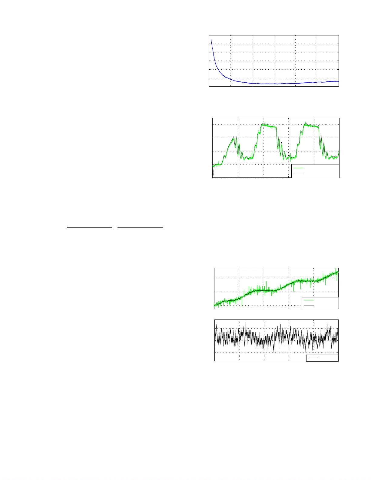
Lead-Lag-Shaped Interac ti v e F orce Estimati on by Equi v ale nt Output Injection of Sliding-Mode Michael Ruderman University of Agder (UiA), Post box 422, 46 04-Kristiansan d, Norway Email: michael.ruderm an@uia.no Abstract —Estimation of in t eractiv e for ces, which are mostly unav ailable for direct measurement on the in terface between a system and its en vironment, is an essential task in various motion control applications. This p aper proposes an interactive for ce estimation method, b ased on t h e well-k n own equivalent output injection of the second-order sliding mode. The equivalent output injection is used to obtain a frequency-unshaped qu antity that appears as a matched external disturbance and encompasses the interactive fo rces. Afterwards, a universal lead-lag shaper , dependin g on dynamics of the motion control syste m coupled with its en vironment, is used to extract an in teractiv e for ce quantity . Once identified , the lead-lag shaper can be app l ied to the given system structure. An experimental case stu dy , using a valv e- controlled hydraulic cylinder counteracted by the d ynamic load, is demonstrated with an accurate estimation of the i nteractiv e fo rce, that in comparison to the reference measurement. I . I N T R O D U C T I O N A N D BAC K G RO U N D Motion c o ntrol applications ar e of ten d ealing with weakly known intera c ti ve forces, which dir ectly affect the contr olled system pe rforman ce and can , in worst case, even provoke instabilities. The co ntrol technolo g ies, where com plying f orces between the system and its environment are cru c ial for a predefined and safe operation, rang e from the nano scale touch- ing devices [1] and medical mechatronics [2], [ 3] to the humano id-like [4], [ 5] and indu strial [6] robo tics, equally as bulky hyd raulic system s [7], [8], he r e just to refer to some of them. While structural dif ferences between the m o tion- and force-co ntrolled sy stem s and their relationship to m echanical impedanc e [9], by inter a ction with environment, have been highligh ted in an ele gant way in [10], the issues related to cou- pling of the interactive force s proved to be challenging. This is especially when shaping the d e sire d endpo in t impedan ce in the real-world servo-systems, see e.g. [11]. Besides, mo re recent experimental s tudies, e.g. [12] in ro botics, demonstrate that an accurate and robust estimation of the co ntact, correspond ingly external, forc e s and torq ues remains a non- tr i vial task, even for re lati vely simple (that case rigid) en vironmental couplin gs and specific tunin g of the mo deled disturbance d ynamics. A. Interaction with en vir on ment For analyz in g coup lings of an inter activ e force, occurrin g on the environmental inter face, con sider a generic two-po rt representatio n S of the actu ated motion system (i.e . ser- vomechanism) wh ich interacts with its en v ironmen t, see blo ck diagram shown in Fig. 1. Recall that the two-p o rt mode ls, correspo n dingly networks, with the associated effort ( F 1 , F 2 ) and flow ( V 1 , V 2 ) variables, and their product representing the instantaneou s input and outp ut power and, hence, energy tr a ns- fer , are particulary useful fo r mo deling interactio n between servomechanisms and en vironments. That allows specifying a mechanical imp edance and de sig ning an imped ance controller [9] which, wh en h as a varying closed-lo o p stiffness, can be seen as a gene ral fo rm of the motion contro l [1 0]. S [ ] 1 2 , T F V [ ] 1 2 , T V F Fig. 1. Ge neric tw o-port of servo mechanism wi th its en vironment. Considering , in the most simple case, a line a r two-po rt model of an in te r activ e motion system (cf. Fig. 1 ), one c a n recogn ize th at the 2 × 2 squa r e matrix S will contain the transfer fun ctions relating to ea ch other th e velocity and force at each po rt, cf. [11]. It is evident that while S ii describe the transfer characteristics of a servomechanism and en vironment, correspo n dingly , the S ij transfer fu n ctions w ith i 6 = j are responsible for the cr oss-couplin g s between both. Assuming i = 1 , 2 for the servomech a nism and en vironment, respecti vely , and S to be regular in terms of invertibility , one can write F 1 V 2 = S − 1 V 1 F 2 (1) for reverse transfer charac teristics of th e co upled interactive system. Introdu cing ¯ S ≡ S − 1 , o ne can recog nize th at the forces of the s ervomechanism a nd en vironmental are additio n - ally balanced by the rate of in duced relati ve motion , meanin g F 1 = ¯ S 12 F 2 + ¯ S 11 V 1 . It is evident that an u nconstraine d relativ e mo tion, i.e. ¯ S 12 ∨ F 2 = 0 , allows to determine the flow quantity o f servomechan isms f rom its effort co unterpa r t and vice versa. As implication, the forward transfer fun ction ¯ S 11 is mostly assumed to be known, corre sp onding ly iden tified, for the used nomin al ser vomech anism. On the contr ary , the cross-coup ling transfer ch aracteristics ¯ S 12 of en vironme n tal interconn ection can be bare ly available an d , as implication , hinder the estimation of external effort variables. Ther efore, an approp riate estimation, or approxim ation, of th e e n viron- mental co uplings can be crucial fo r proper ly rec onstructing the interactive forces which affect the overall contro lled sy stem. Since an interface between the system and its environment is applicatio n-specific, in the most cases, a suitable reshapin g of the interac ti ve fo rce estimate is req uired, onc e th e effort variable F 2 is of a primary inter est. It is worth no tin g that in the most simp le case of a directly matched interactive force (h ere one can think on an ab solutely rigid manipulator h itting a stif f obstacle with unity restitution coefficient and zero d amping) ¯ S 12 will yield the unity or constant transfer characteristics. On the other hand, when thinkin g about a standard so lid (also called Zener) mod el of the viscoelastic type, see e.g. [13] for fundam entals, one can assume ¯ S 12 ( s ) = a b s + 1 c s + 1 , where a, b, c > 0 coe fficients bear the corr e sponding elasticity and viscosity con stants of the associated en vironme n t. Obvi- ously s is the Lap lace variable of the transfer fu nction. O n e can r ecognize th at the a b ove transfer f unction coin c id es with the lead or lag element, for c < b or c > b respecti vely . Wit h the same line o f argumentatio n , various struc tu ral prope rties of en vironmen tal interfaces, like for example thermo-rh e ological, creeping and relaxation, equ ally as v isco -elasto-plastic ef fects, can be incorp orated into shaping the external interactive forces. In general, we assume a gen eric lead-lag sh aper ¯ S 12 ( s ) = a n Y k =1 b k s + 1 c k s + 1 , (2) with a > 0 a nd b k , c k ≥ 0 , while the lead -lag o rder n ≥ 1 is the free structu r al par ameter, dep ending on principles and mechanisms of the interactive force cou plings. B. Contribution and structur e of the paper This paper is contr ibuting to ro bust estimation of the interactive f orces, associate d with environmen ta l impact and constrained respo nse, when no explicit pa r ametric modeling o f the environment interface is provided. The p rincipal structural proper ties of an interactive fo rce, which is ba ck-pro p agated to the actu a to r dynamics of contr o lled mo tion system, are assumed as g e n eral lead-lag characteristics, cf . Section I-A. The cor r espondin g order of the lead-lag shap er is u nderstood to be rather case-specific, that m eans d ependin g o n the prin c ipal behavior of both, mo tion control system and its environment. The pr oposed meth od relies on th e so-called equivalent outpu t injection, see e .g. [14], [15] for d etails, o f the secon d-orde r sliding mode [16], [ 17]. Recall that the latter is ro bust to the unknown bou nded perturb ations, has a finite- tim e convergence proper ty , and is suitab le f o r using th e sing le outpu t of second - order systems, for ma in taining those in the slidin g-mod e . It should also be n oted that an equivalent approach , but inv olving more d etailed explicit modelin g o f n ominal sy stem dy namics, has been recently shown [ 1 8] fo r th e same experimen tal data. Follo wing assumptions are made for the rest of the paper . (i) a time- continuo us system dyn a m ics is unifor mly con- sidered, d espite all real- tim e imp lem entations are using the forward E uler discr etization sche m e 1 . ( ii) in itial conditio ns are negligible so that the transient phases, equally as con vergence phase to the sliding- m ode, are taken o u t ev aluation, corre- sponding ly perf o rmance assessment. ( iii) neither noise by- effects nor sliding- mode related chatterin g ar e within the sco pe of the r ecent work an d, therefor e , neglected in both the an alysis and exper im ental ev aluation. (iv) f or the sake o f g enerality , especially in relation to a robust shaper d esign in frequ ency- domain and lack of an acc urate friction identification (see e.g . [19] for more d etails o n frictional uncertainties) th e dynamic friction effects a r e taken o ut of consider ation. 1 Assumption (i) is justified by the sampling time of 1 millisecon d – twice smaller in the order of magnitude than the time constant s of the system demonstrat ed in the experiment al case study of this work. The main content of th e paper is organized as follows. In Section II the secon d-ord e r sliding mode, correspo ndingly th e associated exact differentiator , a re summarize d fo r the sake of clarity . An optimal parame ter setting, accord in g to [20], is briefly ad d ressed. Th e prop osed estimatio n of in te r activ e force s is describ e d in Section II I, to gether with the cor r espondin g lead-lag shaping of equiv alent output injection. An experi- mental case study , dedicated to pred ic tin g the interactive lo ad forces in a co ntrolled h ydraulic cylinder system, is pr ovid ed in Section IV. The pa p er is concluded by Section V. I I . S E C O N D - O R D E R S L I D I N G M O D E The so-called secon d-orde r sliding mode, see e.g . [16], [17] for fund amentals, app ears when a sliding variable σ satisfies σ = ˙ σ = 0 , (3) while σ = σ ( t, x ) ∈ R is a sufficiently smooth function of time t and system states x , and und e rstood in the Filippov sense [21]. The ma in issue with using h igher ( th an first) o rder sliding modes is the demand on system states to be available, correspo n dingly measura b le 2 . This mean s fo r f ulfilling (3), both σ and ˙ σ sho uld b e d eterminable as f rom th e system states, cf. with Chapter 3 in [1 6]. Single excep tion is the well- known supe r-twisting algorithm (ST A) [24] wh ich needs the measuremen t of σ on ly , fo r steering the system into the second - order slidin g mode . ST A driv es both σ, ˙ σ → 0 in finite tim e, so that a second-or der sliding mode o ccurs af ter the system reaches the glob ally stab le origin ( σ , ˙ σ ) = 0 . Based th e reupon , the first-ord er robust differentiator, intro- duced by Levant in [25], can be written as ˙ ˆ x 1 = K 1 p | e | | e | − 1 e + ˆ x 2 , (4) ˙ ˆ x 2 = K 2 | e | − 1 e. (5) It aims at p roviding an exact e stima tio n of unavailable ˙ σ ( t > T ) ≡ ˆ x 2 quantity , after a finite co n vergence time T > 0 . The estimator dyna mics, given b y (4), (5), is dr iven by the output erro r e = σ − ˆ x 1 , while only the slidin g variable σ ( t ) is available fr om the system measuremen ts. For the approp riately c hosen estimator gains K 1 , K 2 > 0 , which are the ST A para meters [25], th e robust exact differentiator e nsures conv ergence of the states estimation , i.e. e = ˙ e = 0 , and that after finite- time transients. This is ge n erally valid fo r an upper bound ed second-o rder d ynamics, where | ¨ σ | ≤ L = const < ∞ denotes th e Lipschitz constant to be known. The po siti ve constant L is u nderstoo d to u pper boun d the match ed, but unknown, disturb ances of th e n ominal seco nd-or der dynamics. For an optimal ST A ga in setting , one can assume K 1 = 2 . 028 p K 2 , K 2 = 1 . 1 L, (6) as has bee n describ ed and a nalyzed in detail in [2 0]. Her e is is worth notin g th at the ST A gain setting (6) aim s for min im izing the amplitude of fast oscillations, i.e . amplitude o f chattering , in the closed-loop o f ST A estimato r . Further, one can notice that the a bove K 2 -selection, with respect to L , is th e standard one, also for the HOSM d eriv ati ves, as initially pr oposed in 2 This is excluding the approach es where the high-order s liding -mode (HOSM) dif ferent iators [22], [23 ] are used for reconstructin g the dynamic system states from the gi ven single output measurement. [25] and later confir med in mu ltiple works, see e.g . [22], [26], [20]. Th e optimal gain setting (6) has also been recently ev al- uated with experiments in [27]. From the above, it is obvious that an appro p riate gains assignment requir e s the up p er boun d of the disturb ed seco nd-or d er d ynamics to be k nown. This is a well-kn own and studied issue when designin g the ST A- based estimator s, equally as c o ntrol algorith m s, see e.g. [2 8]. If L is unavailable fr om some nomin al system d escription, correspo n dingly design , its approx imativ e estimation is to be obtained ba sed o n the exper imental data. An examp le of such identification appro ach aim ed for determ ining L is shown further on in Section IV, within the provided experimental case study . I I I . E S T I M A T I O N O F I N T E R A C T I V E F O R C E S For estimating the in teractiv e forces o f environment, con- sider a perturb ed seco nd-or der dynam ic system a s ¨ σ = f ( u, σ , ˙ σ, t ) + ξ ( t ) . (7) The unper tu rbed (n ominal) system d ynamics is captured by f ( · ) , including the line ar scaling factor o f the ine r tial mass m . The most simple case, of an actuated un constrained mo - tion 3 , on e a ssum es f = m − 1 u − d ( ˙ σ ) where an a vail- able inpu t value is equivalent to the co ntrolled force of the servomechanism, i.e. u ≡ F 1 . The induc ed motion dyn am- ics is cou nteracted by the velocity-d ependen t dam ping d ( · ) , that is (m ostly) the Coulomb and/o r viscou s friction, both inherent fo r the moving bod ies with be arings, co rrespon dingly contact surfaces, of an actuated relative d isplacement. For a controlled servomechan ism co upled with its environment, the interactive forces are provoking an unkn own, yet up per bound ed, p erturbatio n ξ ( t ) . Th e boun dedness assumption of the p erturbation d y namics follows direc tly fro m the naturally limited in teractive f orces, fo r which | F 2 | < F max is guaran teed for th e finite system acceler ations, input excitations, and some constant F max . Th e bounded ness assumptio n argues again in fa vor of the lead-lag shaped coupling s with environment, cf. (2), me a ning it exclude s the free integrators or d ifferentiators when d etermining ¯ S 12 . W e also stress that d u e to the bo unded - ness assumption of the perturb ed second-or der dynamics, the second-o rder sliding mod e appe ars particulary suitable fo r a robust e stima tio n of the unkn own inter activ e fo r ces. For the p e rturbed c a se of an exact differentiator (4), (5) we introduce th e state estimation error ˜ x 2 = ˙ σ − ˆ x 2 which dynamics is, consequen tly , g overned by ˙ ˜ x 2 = f ( · ) + ξ ( t ) − K 2 | e | − 1 e. (8) Note that th e no minal system dyn amics, here and in the following, is written without explicit argume n ts, this for the sake of simplicity an d for not fo rcing oneself to have time- varying an d full-state-depe ndent dyn amics. The finite-time conv ergence to the second-o rder sliding mo de set ensures that there exists a tim e con stant T > 0 such tha t for all t ≥ T the following ide ntity holds 0 ≡ ˙ ˜ x 2 [15], thus leading to K 2 | e | − 1 e = f ( · ) + ξ ( t ) . (9) Thereup on, an eq u iv alent outp u t injec tion, cf. [15], is χ ≡ K 2 sign( e ) = f ( · ) + ξ ( t ) . (10) 3 The case is considere d in the experiment al study provided in Section IV. Theoretically , an e q uiv alent output injection is deter mined by an infinite switchin g f requen cy of the d isco ntinuou s ter m, which is maintain ing the converged second-o rder sliding mod e. It imp lies th at the spectra l distribution of equiv alent outpu t injection contains b oth, the known part of the m otion d y namics and un known cou pled interactive forc es, in additio n to hig h - frequen t oscillations of th e sliding -mode known as chatter in g [16], [17]. Since the p ractical fin ite- sampling of an estimato r (in origin al work [ 15] also called ob server ) pro duces a hig h but finite switchin g fr equency , the necessity to a p ply a filter to χ becomes self-evident. Most simple case, a finite impulse response (FIR) u nity gain low-pass filter , denoted by h , can be design ed in fre quency dom ain and u sed as a chatter in g cut- off o perator . Th is, rather standard [1 7], filtering ap proach th a t allows u sing an eq u iv alent outp ut injection , will indispensab ly provoke an addition a l phase lag in the estimate ˆ ξ ( t ) ≡ h χ ( t ) − f ( · )( t ) = ξ ( t ) + ε ( t ) . Here ε ( t ) is th e dynam ic pertur bation difference cau sed b y the filtering process, while ε ( s ) → 0 for ω → 0 , f or ω to be the angu lar f requency . Theref ore, the filtering by h causes no errors in the lower frequencies. Instead of low-pass filtering the equ ivalent o utput injection, we make use of the lead-lag transfe r characteristics of the en vironmen tal coupling s, cf. Section I-A. W ith out loss of generality an d n eeds of specif ying th e polyn omial co e fficients and order of (2), we can distinguish two p rincipally different classes of environmental interfaces – of the le a d- or o f the lag- type at h ig her ang ular frequen cies ω . While b oth will appro ach the a -gain at stead y-state, i.e. for ω → 0 , an applica tion- specific finite gain enhan cement will be otherwise expected for the lead- type interfaces at ω → ∞ . Consequen tly logical, a lag-type en vironmen tal interface will exhibit a fin ite g ain- reduction at high f requenc ies, i.e. at ω → ∞ . Falling back on a viscoelasticity type interface mo deling, as explained in Section I-A, some ge n eral rem a rks ca n be drawn to attention . If, du ring the princip al b ehavior o f environmental interface, the elasticity will be dominatin g over v iscosity , a lag-type coupling of th e interactive force s can be expected . On the contrary , a lead- type environmental co upling is to be expected when the v iscosity effects o n the interface domina te over elasticities in the structure. One should keep in mind that th e above disting uishing between the lead- and lag-typ e in terfaces refer to an upp er b ound of the excitation frequen cies. At the same time, an application-sp ecific shaping of th e overall transfer char acteristics of th e coup ling interface is required for 0 < ω < ∞ , thus giving re asoning to the generic shaper (2). The above con siderations allow for using the lead-lag shaper and, with the introd uced transfer function G ( s ) ≡ m ¯ S − 1 12 ( s ) , design ing an infinite impu lse respon se ( IIR) filter g ( · ) , which is the inv erse Lap lace tr ansform of G . It is worth emphasizing that the transf e r characteristics, captured by G , do no t reflect an (artificially) injected low-pass filter, but have a direct relation ship to the cou pling in te r face pr operties of th e system S , cf . Section I-A. Hence, the estimated interactive force can be ob tained from the equiv alent outpu t injection as ˆ F 2 ( t ) = g K 2 sign( e )( t ) − f ( · )( t ) . (11) An essential p oint, to b e eq ually mention ed her e, is that an unav ailable system state can enter th e nomin al dyna mics f ( · ) . This c a se, the state estimate, e.g. ˆ x 2 , h as to be used instead of the u nmeasurab le system q uantity . Y et th is lead s to a feedback - coupled estimator dynamics and, as a log ical consequence , to an additio nal initial per turbations f ( ˆ x 2 )( t ) − f ( ˙ σ )( t ) for t < T , i.e. bef ore the finite-time co n vergence o f the ro bust d ifferentia- tor , cf. Section II. Still, when fairly req uiring the bo unded n ess of an initial state d iscrepancy and BIBO chara cteristics of the nominal dynamic map f ( · ) , on e can n eglect the tran sien t pha se t < T and assumes f ( ˆ x 2 ) ≈ f ( ˙ σ ) ∀ t > T , i.e. once the system is in slidin g-mod e. For the related co n vergence analysis a nd observer stability , in spite of a feedback -coupled estimation dynamics, an interested reader is refer red to [29]. I V . E X P E R I M E N T A L C A S E S T U DY The experim e n tal case stud y is accomp lished on a valve- controlled hydraulic cylinder system, cou nteracted by another cylinder wh ic h a p pears as a dynamic sy stem lo a d. Both cylin- ders are rig id ly c oupled to each other via a sen sing force-ce ll, that allows for dir ect refere nce measur ement of the interacti ve forces which we aim to estimate, co rrespond ingly p redict. More technical details on the experimental setu p of hydraulic system in use can be fo u nd in [30], [31]. The single system parame ter identified prio r to the expe r- imental stud y is the overall lum p ed moving m ass m , which appears as a scaling factor in the tota l force balance. Both , th e shaping lead-lag dyna mics G ( s ) = 1 . 7 2 . 84 × 10 − 5 s + 1 0 . 0013 7 s + 1 · 2 . 38 × 10 − 5 s + 1 0 . 0128 4 s + 1 , (12) and the unknown Cou lo mb friction coefficient γ , resulting in f = m − 1 u − γ sign( ˆ x 2 ) = 0 . 5 882 u − 160 sig n ( ˆ x 2 ) , (13 ) are identified simultaneously , by a standard num erical mini- mization routin e, u sing the measured reference force data. Since L r emains th e single unkn own design param eter of the ST A-based estimator, th e propo sed approac h a im s a t determinin g it v ia numerica l optimization . Th at is perfo rmed on experimenta l data o f th e single measured o utput. Here it is worth to re call that the referen ce fo rce measurem ent can be unav ailable d uring the design stage. Solving minimizatio n min L N X i =1 e ( L ) 2 , (14) of the squared outp u t error yields L = 3 . 1 . Here N is the size of the m easured and ST A-estimated data , while the o utput err or e dep ends o n the L -assignment affecting the ST A-gains cf. (6). The c umulative squar ed erro r (14) is shown in Fig. 2 ag ainst the varying L , ou t of which an optimal L -value is r ead off. The ref erence measur e d interacti ve fo rce, used for the above paramete r s identification , is shown versus the estimated one in Fig. 3. One can recogn ize both time series ar e well in accord with each other, and that fo r transient, oscillating, and qu asi steady- state values of lower (about 10 00 N) an d higher (about 6000 N) amp litu des. T he c o rrespon ding motion profile, with the measured an d estimated quantities of relative displacement and velocity , a re shown in Fig. 4 (a) an d (b) respectively . One can reco g nize a relatively h igh le vel of the displacement measuremen t no ise which indirec tly argue s in 0 1 2 3 4 5 6 0 0.5 1 1.5 2 2.5 3 L Squared error Fig. 2. Cumulati ve squared error against va rying L . 0 0.5 1 1.5 2 2.5 −2000 0 2000 4000 6000 time (sec) interactive force F 2 (N) reference measured estimated Fig. 3. Estimated intera cti v e force ˆ F 2 versus reference measured F 2 . fa vor of the r obust sliding - mode-b ased estimation scheme. From Fig. 4 (b) o ne can fur ther recogn ize, that the relative motion is with relatively low velocity a mplitudes. The velocity pattern is freq uently o scillating in a stick-slip mann er , also with multip le spor adic ze r o-crossing s, that is typical for slower displacements under impact o f a high process n oise and external perturba tio ns, c f . Fig. 4 (a). 0 0.5 1 1.5 2 2.5 0 0.004 0.008 time (sec) position (m) (a) measurement estimation 0 0.5 1 1.5 2 2.5 −0.02 0 0.02 time (sec) velocity (m/sec) (b) estimation Fig. 4. Traj ectori es of induced m otion with interacti v e force, measured versus estimate d relati ve displacement (a) and estimated relati v e velocit y (b) Another set of u nseen data, i.e. not involv ed into parame- ters iden tification, has been equally used f or ev aluating the estimation of an in teractiv e force. Here the estimated and referenc e measured interactive f orce values are shown opp osite to eac h other in Fig. 5. T his time, the inter activ e fo rce has mo re steeply periodic pea ks, co ming from the saw-shaped profile of th e app lied coun teracting load, an d the longe r steady -state 0 0.5 1 1.5 0 2000 4000 6000 time (sec) interactive force F 2 (N) reference measured estimated Fig. 5. Estimated interacti ve force ˆ F 2 versus reference measured F 2 . plateaus in- between, c f. Fig. 5. Also here on e can recog nize a good accord between the estimation and m e asurement. V . C O N C L U S I O N S For robust estima tio n of the unknown interactive for c es, a method b ased of the seco nd-or d er sliding- mode and a ssocia te d equiv alent o utput in jec tion principles has been proposed. It is shown that, depend ing on the system dy namics and intera c ti ve force cou plings, which appe ar as m atched perturba tions, the equiv alent o utput injection can be resh a ped via the stan- dard lead-la g tr ansfer character istics. Design of the estimation method is presented along with the p a rametrization of an exact differentiator [25] and the pr oposed strategy of re shaping the e quiv alent ou tput injection quantity . An experimental case study , showing an accur a te estimation of the in teractiv e fo rce in the dy namically loaded valve-controlled h ydraulic cylinder with high measureme n t and pro cess n oise, is p rovided for ev aluation o f the proposed method. A C K N O W L E D G M E N T This work has r eceiv ed fun ding f rom the European Unio n Horizon 2020 research and innovation pr ogramm e H20 20- MSCA-RISE-2016 und er the gr a n t agreement No 734832. Discussions with Prof. Leon id Fridman on equ i valent output injection princip les are f urther gratefully acknowledged. R E F E R E N C E S [1] M. Sitti and H. Hashimoto, “T el eopera ted touch feedback from the surfac es at the nanoscale : m odelin g and experiment s, ” IEEE /ASME T rans. on Mechat r onic s , vol. 8, no. 2, pp. 287–298, 2003. [2] S. Katsura, W . Iida, and K. Ohnishi, “Medical mechatronic s - an applic ation to haptic forces, ” Annual Revie ws in Contr ol , vol. 29, no. 2, pp. 237–245, 2005. [3] N. Z emiti, G. Morel, T . Ortmaier , and N. Bonnet, “Mechatronic design of a new robot for force control in minimally in vasi v e surgery , ” IEEE/ASME T rans. on Mec hatr onics , vol. 12, no. 2, pp. 143–153, 2007. [4] D. Pratti chizz o, M. Malvezz i, M. Gabicci ni, and A. Bicchi, “On motion and force controll abili ty of precision grasps with hands actuate d by soft synergi es, ” IEE E T rans. on Robotics , vol. 29, pp. 1440–1456, 2013. [5] F . Abi-Farra j, B. Henze, C. Ott, P . R. Giordano, and M. A. Roa, “T orque-based balancing for a humanoi d robot performing high-force intera ction tasks, ” IEEE R obotic s and Automatio n Letter s , vol. 4, no. 2, pp. 2023–2030, 2019. [6] A. Alcocer , A. Robertsson, A. V alera, and R. Johansson, “Force estimati on and control in robot manipulators, ” IF A C Procee dings V ol- umes , vol. 36, no. 17, pp. 55–60, 2003. [7] N. Niksefat and N. Sepehri, “Design ing robust force control of hydraulic actua tors despite system and env ironmenta l uncertai nties, ” IEEE Con- tr ol Systems Magazine , vol. 21, no. 2, pp. 66–77, 2001. [8] J. Koi vum ¨ aki and J . Mattila, “Stability-g uarante ed force-se nsorless contac t force/motio n control of hea vy-duty hydrauli c manipul ators, ” IEEE Tr ans. on Robotics , vol. 31, no. 4, pp. 918–935, 2015. [9] N. Hogan, “Impedance control : An approach to manipulat ion, ” J ournal of dynamic systems, measurement , and contr ol , vol. 107, no. 1, 1985. [10] K. Ohnishi, N. Matsui, and Y . Hori, “Estimation, identifica tion, and sensorless control in motion control system, ” Pr oceedi ngs of the IEEE , vol. 82, no. 8, pp. 1253–1265, 1994. [11] S. P . Buerger and N. Hogan, “Complementary stabil ity and loop shaping for improv ed human–robot interac tion, ” IEE E T rans. on Robotics , vol. 23, no. 2, pp. 232–244, 2007. [12] A. W ahrburg, J. B ¨ o s, K. D. Listmann, F . Dai, B. Matth ias, and H. Ding, “Motor -curren t-based estimation of cartesian contact forces and torques for robotic manipulato rs and its applicati on to force control , ” IEE E T rans. on Autom. Science and Eng. , vol. 15, pp. 879–886, 2018. [13] N. W . Tschoegl, The phenomenolog ical theory of linear visco elastic behavio r: an intr oduc tion . Springer Science, 2012. [14] C. Edwards, S. K. Spurgeon, and R. J. Patt on, “Sliding mode observers for fault detectio n and isolation, ” Automatica , vol. 36, no. 4, pp. 541– 553, 2000. [15] J. Davil a, L. Fridman, and A. Poznyak, “Observa tion and identificat ion of m echani cal s ystems via second order sliding modes, ” Int. Journa l of Contr ol , vol. 79, no. 10, pp. 1251–1262, 2006. [16] W . Perruquetti and J. P . Barbot, Sli ding mode contr ol in enginee ring . M. Dekke r Publisher , 2002. [17] Y . Shtessel, C. Edwards, L. Fridman, and A. Lev ant, Sliding mode contr ol and observation . Springer , 2014. [18] M. Ruderman, L . Fridman, and P . Pasol li, “V irtu al sensing of load forces in hydraulic actuators using second- and higher-order sliding modes, ” Contr ol Engineering Practice , vol. NN, no. pp, 2019. [19] M. Ruderman and M. Iwasak i, “Observer of nonlinear friction dynamics for motion control, ” IEEE T ran s. on Industrial E lect r onics , vol. 62, no. 9, pp. 5941–5949, 2015. [20] U. P . V ent ura and L. Fridman, “Design of super-twisti ng control gains: a describi ng functio n based methodology , ” Automatic a , vol. 99, pp. 175– 180, 2019. [21] A. Filippov , Differ ent ial equations with discontinuo us right-hand sides . Kluwer Academic Publishers, 1988. [22] A. Le v ant, “Higher-orde r sliding modes, dif ferenti ation and output- feedbac k control, ” Int. Jo urnal of Contr ol , vol. 76, pp. 924–941, 2003. [23] E. Cruz-Zav al a and J. A. Moreno, “Le v ant’ s arbit rary order exa ct dif- ferenti ator: A L yapun ov approach, ” IE EE T ran s. on Automatic Contr ol , pp. 1–1, 2018. [24] A. Le v ant, “Sliding order and sliding accurac y in sliding m ode control, ” Int. J ournal of Contr ol , vol. 58, no. 6, pp. 1247–1263, 1993. [25] A. L e v ant, “Robust ex act differen tiati on via s liding mode techn ique, ” Automat ica , vol. 34, no. 3, pp. 379–384, 1998. [26] M. Reichhartin ger and S. Spurgeon, “ An arbitrary -order diffe renti ator design paradigm with adapti v e gains, ” Int. Journa l of Contr ol , vol. 91, no. 9, pp. 2028–2042, 2018. [27] M. Ruderman and L. Fridman, “Use of second-orde r sliding mode observe r for low-ac curac y s ensing in hydraulic machine s, ” in IEEE 15th Int. W orkshop on V ariable Structur e Systems and Sliding Mode Contr ol (VSS18) , 2018, pp. 315–318. [28] A. L e v ant, “Principl es of 2-sliding m ode design, ” Automatica , vol. 43, no. 4, pp. 576–586, 2007. [29] J. Davila , L. Fridman, and A. Le v ant, “Second-order sliding-mode observe r for mechanical systems, ” IEEE T rans. on Automatic Contr ol , vol. 50, no. 11, pp. 1785–1789, 2005. [30] P . Pasolli and M. Ruderman, “Lineariz ed piece wise af fine in control and s tates hydraulic system: Modeling and identificati on, ” in IEEE 44th Annual Confere nce of the Industrial Electr onics Society , 2018, pp. 4537–4544. [31] P . Pasolli and M. Ruderman, “Hybrid state feedback position- force control of hydraulic cylinder , ” in IEEE Int. Confere nce on Mechat r onic s (ICM) , 2019, pp. 54–59.
Original Paper
Loading high-quality paper...
Comments & Academic Discussion
Loading comments...
Leave a Comment