Optimal Planning and Operation of Multi-Frequency HVac Transmission Systems
Low-frequency high-voltage alternating-current (LF-HVac) transmission scheme has been recently proposed as an alternative solution to conventional 50/60-Hz HVac and high-voltage direct-current (HVdc) schemes for bulk power transfer. This paper propos…
Authors: Quan Nguyen, Surya Santoso
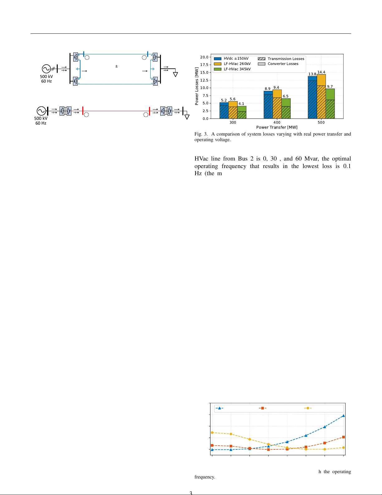
c 2019 IEEE. Personal use of this material is permitted. Permission from IEEE must be obtained for all other uses, in any current or future media, including republishing this material for advertising or promotional purposes, creating ne w collectiv e works, for resale or redistrib ution to servers or lists, or reuse of any cop yrighted component of this work in other works. Optimal Planning and Operation of Multi-Frequenc y HV ac T ransmission Systems Quan Nguyen, Student Member , IEEE, and Surya Santoso, F ellow , IEEE Abstract —Low-frequency high-voltage alternating-current (LF-HV ac) transmission scheme has been recently pr oposed as an alternativ e solution to con ventional 50/60-Hz HV ac and high-voltage direct-current (HVdc) schemes f or b ulk power transfer . This paper proposes an optimal planning and operation for loss minimization in a multi-frequency HV ac transmission system. In such a system, con ventional HV ac and LF-HV ac grids are interconnected using back-to-back (BTB) con verters. The dependence of system MW losses on con verter dispatch as well as the operating voltage and frequency in the LF-HV ac is discussed and compared with that of HVdc transmission. Based on the results of the loss analysis, multi-objecti ve optimization formulations for both planning and operation stages are proposed. The planning phase decides a suitable voltage lev el for the LF-HV ac grid, while the operation phase determines the optimal operating fr equency and po wer dispatch of BTB con verters, generators, and shunt capacitors. A solution approach that effectively handles the variations of transmission line parameters with the rated voltage and operating frequency in the LF-HV ac grid is proposed. The proposed solutions of the planning and operation stages ar e evaluated using a multi-frequency HV ac system. The results show a significant loss reduction and improv ed voltage regulation during a 24-hour simulation. Index T erms —low-frequency transmission, optimal power flow , back-to-back conv erter , transmission planning and operation. I . N O M E N C L A T U R E Subscript ∗ denotes the transmission scheme of the power system: s 50/60-Hz HV ac transmission system, l LF-HV ac transmission system, Sets: N ∗ set of buses in a grid, D ∗ set of transmission lines, G ∗ set of buses connected to generators, L ∗ set of non-voltage-controlled buses, C ∗ set of buses connected to con verters, V ∗ set of buses connected to conv erters op- erating in voltage-controlled mode, N sh ∗ set of buses with shunt capacitors, Q sh ∗ ,k set of discrete dispatch of the shunt ca- pacitor at bus k , Parameters: P load s , Q load s loads at buses in HV ac grid s , g ∗ , b ∗ line series conductance and susceptance, V sch ∗ scheduled voltage magnitude at voltage- controlled buses, ¯ V , ¯ V lower and upper load voltage limits, ¯ I ∗ maximum line current, ¯ P ∗ maximum line real power , Y ∗ , G ∗ , B ∗ admittance, conductance, and suscep- tance matrices, α 1 , α 2 , α 3 weighting coefficients, V ariables: V l , F l optimal operating voltage and frequency of LF-HV ac transmission system l , e ∗ , f ∗ real and imaginary parts of voltages, P ∗ , Q ∗ injected power into grid from buses, P g en ∗ , Q g en ∗ generator dispatch, P conv ∗ , Q conv ∗ power from/to BTB con verters, Q sh ∗ injected reactiv e power into grid from shunt capacitors at 1 pu. I I . I N T RO D U C T I O N In spite of the increasing penetration of distributed ener gy resources in the distribution system, the transmission system plays an ev er-important role in transporting bulk po wer over long distances. Proposed supergrids in Europe and Asia, as well as, the increasing number of offshore wind farms provide a motiv ation to seek an improved and alternativ e b ulk po wer transmission scheme [1]–[3]. Compared to the con ventional 50/60-Hz high-voltage alternating current (HV ac) transmission systems, conv erter-based high-voltage direct current (HVdc) systems have shown unique benefits of unrestricted point- to-point bulk-po wer transfer capability over long distances, reduced line losses, and narro wer right of way . Howe ver , reliable HVdc operation is confronted by the immature dc circuit breakers in fault clearing. This operational challenge considerably impedes the feasibility of replicating multi-point interconnection capability of HV ac systems. Considering the limitations of conv entional HV ac and HVdc technology , growing attention has turned to an alternative solution for bulk-po wer transmission, which is called low- frequency HV ac (LF-HV ac). LF-HV ac offers the advantages of the two existing technologies, such as high power-carrying capability ov er long distance, straightforward ac protection system, and the flexibility of multi-terminal networks [4]– [6]. A significant reduction in reactance at low frequency also improv es voltage profiles and system stability [7]–[9]. Similar to HVdc systems, an LF-HV ac system requires power con verters for connection to a con ventional 50/60-Hz HV ac system, which forms a multi-frequency po wer system. Con- verter topologies proposed to perform the connection include ac/ac cyclocon verters, ac/ac modular multi-le vel con v erters (MMC), and ac/dc/ac back-to-back (BTB) con verters. In this paper , the BTB configuration is chosen as the con verter topol- ogy because it allows a smaller filter size while of fering full power and frequency control capabilities [10]–[12]. Existing control techniques and equipment in HVdc systems can also be directly adopted for BTB con verters. Sev eral research has been done to ev aluate the potential applications and performance of an LF-HV ac grid as a stan- dalone system as well as a part of a generalized multi- 1 c 2019 IEEE. Personal use of this material is permitted. Permission from IEEE must be obtained for all other uses, in any current or future media, including republishing this material for advertising or promotional purposes, creating new collectiv e works, for resale or redistribution to servers or lists, or reuse of any copyrighted component of this work in other works. frequency system. Practical 16.7 Hz LF-HV ac transmission for European offshore wind farms are proposed in [13]–[15]. In [10], [16], a laboratory-scale point-to-point LF-HV ac line is designed and simulated using a real-time hardware-in-the- loop platform to verify the concept and control capability for offshore applications. Since an LF-HV ac grid is designed to transfer bulk po wer , minimizing its losses leads to a significant total loss reduction in the entire system. In [17], a comparison of power losses and costs between HVdc and LF-HV ac transmission lines with the length up to 250 km and at a frequency range from 10 to 16.7 Hz are shown. A selection of an optimum frequency based on transmission range is also included. Howe ver , the voltage of the LF-HV ac grid, real power transfer, and reacti ve power support from BTB conv erters, which greatly affect system losses and the optimal frequency , are not discussed. Therefore, a system-wide model is mandatory to accurately e valuate suitable voltage lev els and operating frequencies for a multi-terminal LF-HV ac grid in a multi-frequency HV ac system. In [18], po wer flo w formulation and solution for such a multi-frequency system are proposed. Ho wev er , the chosen rated voltage, operating frequency , and scheduled po wer transfer do not guarantee an optimal performance in terms of losses and voltage regulation. As an extension of the existing works on the emerging LF- HV ac transmission technology , the main contributions of this paper are: • A loss study and comparison between LF-HV ac and HVdc transmission schemes, with respect to scheduled power transfer , system voltage, and operating frequenc y . The re- sults of this comparison show the need of a generalized system-wide OPF model to achiev e an optimal operation in a multi-frequency system. • Multi-period multi-objectiv e OPF formulations for planning and operation stages of a multi-frequency HV ac system. During the planning stage, a suitable voltage for the LF- HV ac grid is determined to achieve minimum losses. During the operation phase, the actual optimal frequency and dis- patch from generators, shunt capacitors, and conv erters are determined giv en real-time load data, subjected to compre- hensiv e operational constraints of all ac grids and con verters. • An scalable and effecti ve solution approach to handle the variations of transmission line parameters with the rated voltage and operating frequency in the power flo w con- straints of the LF-HV ac grid. I I I . O P E R A T I O N O F B AC K - T O - B A CK C O N V E T E R S I N A M U LTI - F R E Q U E N C Y H V AC P O W E R S Y S T E M This section briefly describes the operation of BTB conv ert- ers in a multi-frequency HV ac system. Fig. 1 shows the model and control of each BTB con verter , which consists of two VSC denoted as VSC 1 and VSC 2 . These conv erters hav e identical structures and electrical components such as a transformer, a phase reactor , and switching devices. These two con verters share a common dc-link capacitor with a constant dc voltage that allows decoupled operation of VSC 1 and VSC 2 . When n BTB conv erters are used to connect HV ac grid s and LF-HV ac grid l , the following operating modes are applied to regulate the power transfer , dc-link voltage, and/or ac terminal voltage magnitude of n -1 BTB con verters [18]: • Con verter VSC 1 , which is connected to HV ac grid s , is set to regulate real and reactiv e power (PQ mode) or real power and ac terminal voltage magnitude (PV mode). This means that P conv s,k and Q conv s,k in PQ mode or P conv s,k and V s,k in PV mode are known parameters. • Con verter VSC 2 , which is connected to LF-HV ac grid l , is set to regulate the dc-link voltage V dc,k and to control either reacti ve po wer (QV dc mode) or the ac terminal v oltage magnitude (VV dc mode). This implies that either Q conv l,k in QV dc mode or V l,k in VV dc mode is a known quantity while P conv l,k is always unknown and needs to be determined. This approach does not apply to a BTB con verter that is connected to the slack b us in LF-HV ac grid l . At the VSC 2 side of this slack conv erter , P conv l,sl and Q conv l,sl vary to account for the losses in the LF-HV ac grid and control voltage magnitude V l,sl at the slack bus. The voltage angle of the slack bus is also considered as the reference angle for other buses in grid l . At the VSC 1 side of this BTB con verter , only the reactiv e power Q conv s,sl is controlled. The real power P conv s,sl is unknown since it depends on the unknown real power P conv l,sl , Joule losses due to the resisti ve elements of transformer and reactor impedances ¯ Z T 1 , ¯ Z c 1 , ¯ Z T 2 , and ¯ Z c 2 , and switching losses in VSC 1 and VSC 2 con verters. I V . D E P E N D E N C E O F L O S S E S O N V O LT AG E , F R E Q U E N C Y , A N D R E AC T I V E P O W E R S U P P O RT I N L F - H V AC G R I D This section presents a comparison on losses between two 200-km transmission lines employing HVdc and LF-HV ac schemes, as shown in Fig. 2, under different scheduled power transfer , system voltage, and operating frequency . Back- to -Back Converter Station 50 / 60 -Hz HVac Gr id s LF -HVac Grid l I s,k V s,k Q s,k conv P s,k conv V dc ,k VSC 1 VSC 2 I c2,k V l,k Q l,k conv P l,k conv Z c2,k V c1,k Z f1,k Z c1,k Z T1,k I c1,k V c2,k Z f2,k Z T2,k I l,k + - + - V s,k * Q s,k conv * V dc ,k * V s,k + - Q s,k conv + - V l,k * Q l,k conv * V l,k Q l,k conv + - P s,k conv * + - P s,k conv V dc ,k P l,k conv * P l,k conv + - Q s,k P s,k Q s,k P s,k gen gen Q s,k P s,k load load Q l,k P l,k Q l,k P l,k gen gen Q s,k sh Q l,k sh Fig. 1. A BTB conv erter is used to connect an LF-HV ac grid to a 50/60-Hz HV ac grid: the system configuration, the interface between the two grids, and the main control blocks. 2 c 2019 IEEE. Personal use of this material is permitted. Permission from IEEE must be obtained for all other uses, in any current or future media, including republishing this material for advertising or promotional purposes, creating new collectiv e works, for resale or redistribution to servers or lists, or reuse of any copyrighted component of this work in other works. P s,1 conv Q s,1 conv P s,2 conv Q s,2 conv 200 km , 150 kV Bipolar HVdc line P l,1 conv P l,2 conv 1 pu 1 2 (a) 200 km 3-phase LF-HVa c l i ne 1 pu P s,1 conv P l,1 conv Q s,1 conv Q l,1 conv P l,2 conv P s,2 conv Q l,2 conv Q s,2 conv 1 2 V l , F l (b) Fig. 2. a) A 200-km line employing bipolar HVdc (adopted from BorWin1 system in Germany [19]), and b) an alternative configuration employing LF- HV ac transmission. The HVdc grid shown in Fig. 2(a) is operated at ± 150 kV and in bipolar topology . The number of VSCs is thus equal to that in the LF-HV ac grid. The power transfer and losses of a bipolar configuration is similar to a double circuit of monopolar 150-kV HVdc but with a significantly less ground current. The LF-HV ac grid shown in Fig. 2(b) is operated at rated voltage V l and frequency F l . The voltage at the sending- end buses, i.e. Bus 1, in both HVdc and LF-HV ac grids is kept at 1 pu. In the base case, the two lines deliv er same desired amounts of real power P conv s, 2 from an ideal voltage source in a 60-Hz HV ac grid to a remote load. Several assumptions and insights of the comparison are as follows: • The electric components such as transformers, phase reac- tors, and switching devices in all VSC stations are identical. • Reactiv e power Q conv s, 1 withdrawn from the ideal 60-Hz voltage source and Q conv s, 2 consumed by the load, which hav e similar ef fects in system losses, are set to zero for simplicity . • VSC con verters at Bus 1 and Bus 2 in the LF-HV ac grid can supply and absorb reactiv e po wer from the grid. The comparison is conducted using the PSCAD/EMTDC time- domain simulation program and verified by a power flow tool for multi-frequency HV ac - HVdc systems reported in [18]. Fig. 3 shows the total system losses, including transmission loss and con verter losses in the HVdc and LF-HV ac grids at different power transfer and rated v oltages. The operating frequency of the LF-HV ac line is fixed at 10 Hz. It is expected that a higher system voltage and/or a lo wer power transfer results in a lower transmission loss. More importantly , it is shown that the transmission losses of the LF-HV ac trans- mission lines are comparable or less than that of the HVdc transmission line. In this study , an LF-HV ac voltage of 260 kV is chosen because the corresponding line-to-neutral voltage is equal to the 150 kV line-to-ground HVdc voltage. Another LF-HV ac voltage of 345 kV is chosen because it is close to the equiv alent 300 kV line-to-line voltage of the bipolar ± 150-kV HVdc system. Fig. 4 sho ws the dependence of the transmission loss and receiving-end v oltage of the LF-HV ac line on the operating frequency when V l = 260 kV and P conv s, 2 = 400 MW . It is sho wn that for different reacti ve po wer schedules at the receiving end, the minimum transmission loss occurs at different frequencies. In this case, when the reacti ve po wer injected to the LF- 300 400 500 Power Transfer [MW] 0.0 2.5 5.0 7.5 10.0 12.5 15.0 17.5 20.0 Power Losses [MW] 5.2 5.6 4.1 8.9 9.4 6.5 13.8 14.4 9.7 H V d c ± 1 5 0 k V LF-HVac 260kV LF-HVac 345kV Transmission Losses Converter Losses Fig. 3. A comparison of system losses varying with real power transfer and operating voltage. HV ac line from Bus 2 is 0, 30 , and 60 Mv ar , the optimal operating frequency that results in the lo west loss is 0.1 Hz (the minimum analyzed frequency), 10 Hz, and 25 Hz. In general, the optimal frequency is the one at which the combination of the supplied and consumed reactiv e power from line capacitance, line reactance, and con verter results in the smallest line current. It is also important to note that VSC con verters might increase the supply or absorption of reactiv e power from the line to reduce transmission losses. Howe ver , such a decision might increase con verter losses and thus the total system losses. Fig. 5 shows the receiving-end voltage of the LF-HV ac grid corresponding to the analysis shown in Fig. 4. It can be seen that the optimal frequency that results in the best voltage regulation without reacti ve power support from the conv erter at the receiving end, i.e. Q conv l, 2 = 0 Mvar , is 0.1 Hz. Howe ver , when Q conv l, 2 is 30 Mvar or 60 Mvar , the optimal frequency in terms of voltage regulation is 15 Hz and 25 Hz, respectively . The abov e results show that rated voltage and operating frequency of the LF-HV ac grid as well as the scheduled real and reacti ve power transfer significantly affect the transmission loss and voltage regulation. Due to the nonlinear characteristic of power flo w model, it is not straightforward to determine exactly their best combination, i.e. the optimal operating point, that results in lo west system losses or best voltage regulation. Therefore, to achiev e a successful and optimal operation of a multi-frequency HV ac system, it is important to determine a suitable voltage for the LF-HV ac grid during the planning phase as well as an optimal coordination between control resources in the conv entional 50/60-Hz HV ac grid, LF-HV ac grid, and the BTB con verters connecting the grids during the 0. 1 1. 0 5. 0 10. 0 15. 0 20. 0 25. 0 30. 0 Fr e q ue nc y F l [ Hz] 6. 8 6. 9 7. 0 7. 1 7. 2 T r a nsm i ssi o n Lo sse s [ M W] Q c o nv l , 2 = 0 M va r Q c o nv l , 2 = 30 M va r Q c o nv l , 2 = 60 M va r Fig. 4. A comparison of transmission losses varying with the operating frequency . 3 c 2019 IEEE. Personal use of this material is permitted. Permission from IEEE must be obtained for all other uses, in any current or future media, including republishing this material for advertising or promotional purposes, creating new collectiv e works, for resale or redistribution to servers or lists, or reuse of any copyrighted component of this work in other works. 0. 1 1. 0 5. 0 10. 0 15. 0 20. 0 25. 0 30. 0 Fr e q ue nc y F l [ Hz] 0. 96 0. 97 0. 98 0. 99 1. 00 1. 01 Re c e i vi ng - e nd Vo l ta g e [ p u] Q c o nv l , 2 = 0 M va r Q c o nv l , 2 = 30 M va r Q c o nv l , 2 = 60 M va r Fig. 5. A comparison of receiving-end voltage of the LF-HV ac grid varying with the operating frequency . The receiving-end voltage of the HVdc grid shown in Fig. 2(a) at a similar power transfer P conv s, 2 = 400 MW schedule is 0.981 pu. P l a nni ng s t a g e - M in i m iz e s y s t e m lo s s e s a n d r a t e d v o lt a g e V l o f LF - H V a c g r id . - U s e fo r e c a s t lo a d d a t a ( o n ly m in im u m a n d p e a k - lo a d p e r io d s ). - A ll c o n t r o l r e s o u r c e s . Fix V l = V l * O pe r a t i on s t a g e - M in i m iz e s y s t e m lo s s e s a n d c a p a c i t o r s w it c h in g . - U s e m u lt i - p e r io d r e a l - t i m e lo a d d a t a . - R e m a in in g c o n t r o l r e s o u r c e s . O p t im a l r e a l - t i m e d is p a t c h A c t ua l s y s t e m R e a l - t i m e s y s t e m s t a t u s Fig. 6. The two optimization problems associated with the planning and operation phases. operation period. V . O P T I M A L P L A N N I N G A N D O P E R A T I O N O F A G E N E R A L I Z E D M U L T I - F R E Q U E N C Y S Y S T E M This section presents tw o OPF problems for planning and operation stages in a generalized multi-frequency system. The relation between the two problems are shown in Fig. 6. A. Planning Stage: Optimal V oltag e of the LF-HV ac Grid In the planning stage, an optimization problem is formulated to determine an optimal transmission voltage rating V l of LF- HV ac grid l , giv en a desired po wer transfer based on demand forecasting. Additionally , preliminary operating frequency F l and dispatch from generators, shunt capacitors, and con verters are determined. System losses are minimized by minimizing the total generation in HV ac grid s and LF-HV ac grid l . A variable vector X is defined as a combination of state variables x and control variables u as follows: X = [ x | u ] = [ e s , f s , e l , f l | V l , F l , P g en s , Q g en s , Q sh s , P g en l , Q g en l , Q sh l , P conv s , Q conv s , P conv l , Q conv l ] . (1) A weighted-sum multi-objective function comprising the total generation and optimum voltage rating of grid l is defined as follows: f ( X ) = α 1 X k ∈G s P g en s,k + X k ∈G l P g en l,k + α 2 V l . (2) Equality and inequality constraints for grids s and l as well as con verters are defined as follows: In HV ac grid s , the equality constraints g s representing the po wer balance at ev ery bus k and the voltage magnitude requirement at voltage controlled buses, are giv en by: g P s,k ( X ) = P s,k − ( P g en s,k − P load s,k − P conv s,k ) = 0 , ∀ k ∈ N s , (3) g Q s,k ( X ) = Q s,k − [ Q g en s,k − Q load s,k − Q conv s,k − ( e 2 s,k + f 2 s,k ) Q sh s,k ] = 0 , ∀ k ∈ N s , (4) g V s,k ( X ) = e 2 s,k + f 2 s,k − V sch s,k 2 = 0 , ∀ k ∈ G s ∪ V s . (5) The injected po wer P s,k and Q s,k to grid s at bus k in (3) and (4) are giv en by: P s,k = G s,k : ( e s,k e s + f s,k f s ) + B s,k : ( f s,k e s − e s,k f s ) , (6) Q s,k = G s,k : ( f s,k e s − e s,k f s ) − B s,k : ( e s,k e s + f s,k f s ) , (7) where G s,k : and B s,k : are the the k th row of the conductance and susceptance matrices G s and B s . The inequality con- straints in HV ac grid s represent the lower and upper limits of generators, discrete capacitor dispatch, and load v oltages, which are giv en as follo ws: ¯ P g en s,k ≤ P g en s,k ≤ ¯ P g en s,k , ∀ k ∈ G s , (8) ¯ Q g en s,k ≤ Q g en s,k ≤ ¯ Q g en s,k , ∀ k ∈ G s , (9) Q sh s,k ∈ Q sh s,k , ∀ k ∈ N sh s , (10) ¯ V 2 ≤ h V s,k ( x ) = e 2 s,k + f 2 s,k ≤ ¯ V 2 , ∀ k ∈ L s . (11) In LF-HV ac grid l , similar constraints as in (3) - (11) hold. V oltage constraint (11) is imposed to all buses in grid s since it is assumed that they do not to serve any loads. In addition, the rated v oltage and operating frequency are constrained as follows: ¯ F l ≤ F l ≤ ¯ F l , (12) ¯ V l ≤ V l ≤ ¯ V l . (13) For LF-HV ac grid l , line parameters vary with the rated v oltage V l and operating frequency F L . Therefore, it is important to note that the conductance and susceptance matrices G l and B l in (6) and (7) are functions of V l and F l . In this planning phase, line current and power limits in both HV ac grid s and LF-HV ac grid l are not taken into account. Such a treatment allows a tractable solution to determine the optimal rated voltage V l . In the BTB con verter systems that connects grids s and l , as sho wn in Fig. 1, the equality constraints representing the real po wer balance between VSC 1 and VSC 2 , are defined as follows: g P c,k ( X ) = P conv l,k + P J 2 ,k + P sw 2 ,k + P J 1 ,k + P sw 1 ,k − P conv s,k = 0 , (14) where the Joule loss ( P J ) and switching loss ( P sw ) at either VSC 1 or VSC 2 side are quadratic functions of the correspond- ing injected/withdrawn power P conv and Q conv as well as the voltage magnitude V s or V l at the ac terminal in grid s or grid 4 c 2019 IEEE. Personal use of this material is permitted. Permission from IEEE must be obtained for all other uses, in any current or future media, including republishing this material for advertising or promotional purposes, creating new collectiv e works, for resale or redistribution to servers or lists, or reuse of any copyrighted component of this work in other works. l , respectiv ely . The explicit form of (14) in terms of these variables in vector X is giv en as follows [18]: g P c,k ( X ) = P conv l,k + 2 a 0 − P conv s,i + P conv l,k 2 + Q conv l,k 2 e 2 l,k + f 2 l,k ( R 2 ,k + a 2 ) + v u u t P conv l,k 2 + Q conv l,k 2 e 2 l,k + f 2 l,k a 1 + P conv s,k 2 + Q conv s,k 2 e 2 s,k + f 2 s,k ( R 1 ,i + a 2 ) + v u u t P conv s,k 2 + Q conv s,k 2 e 2 s,k + f 2 s,k a 1 = 0 , (15) where a 0 , a 1 , and a 2 are gi ven coefficients of the loss quadratic function, R 1 ,k = R T 1 ,k + R c 1 ,k , and R 2 ,k = R T 2 ,k + R c 2 ,k with R T 1 ,k , R T 2 ,k , R c 1 ,k , and R c 2 ,k being the winding resistances of the transformers and phase reactors. The inequality constraints that form the feasible operating region for VSC 1 and VSC 2 include: 1) the limit of conv erter current I c 1 and I c 2 to av oid ov erheat- ing for switching devices, 2) the limit of ac-side con v erter v oltage V c 1 and V c 2 by the dc-link voltage V dc to av oid ov er-modulation, and 3) the limit of reactive po wer Q conv absorbed by VSC 1 and VSC 2 from HV ac grid s and LF-HV ac grid l , respectively . These constraints are normally con verted into equi valent con- straints of voltage magnitude and conv erter power at the ac terminal in order to be easily embedded in optimal power flow algorithms. W ithout loss of generality , the follo wing constraints are written using the notation of VSC 1 as follows [20], [21]: 1) I c 1 ,k ≤ I max c,k ⇐ ⇒ ( P conv s,k ) 2 + ( Q conv s,k ) 2 − ( I max c,k ) 2 ( e 2 s,k + f 2 s,k ) ≤ 0 , ∀ k ∈ C s (16) 2) V c 1 ,i ≤ k m V dc,i ⇐ ⇒ [ P conv s,k − ( e 2 s,k + f 2 s,k ) g 1 ,k ] 2 + [ Q conv s,k + ( e 2 s,k + f 2 s,k ) b 1 ,k ] 2 − k m V dc Z 1 ,k 2 ( e 2 s,k + f 2 s,k ) ≤ 0 , ∀ k ∈ C s (17) 3) Q conv s,k ≤ k Q S conv rated,k , ∀ k ∈ C s , (18) where k m and k Q are giv en coefficients, and where ¯ Z 1 ,k = 1/ ( g 1 ,k + j b 1 ,k ) is the combined impedances of the transformer and filters at each VSC side of the BTB conv erter station. It is important to note that the feasible operating region of a VSC formed by (16)-(18) varies with the ac terminal voltage. The properties of the formulated OPF problem during the planning stage and the solution approach are described in Section VI. B. Operation Stage: Real-T ime Operating F r equency of the LF-HV ac Grid and OPF in the Multi-F r equency System The optimal LF-HV ac transmission voltage rating V ? l deter- mined in the planning phase abo ve become a gi ven input to the OPF problem during the multi-period operation with real- time power transfer and load lev els. LF-HV ac grid l optimum operating frequency and generator/con verter/shunt capacitor dispatch in both grids s and l are now determined in the operation phase. The OPF formulation follow planning phase with the following important modifications. The variable vector is defined as in (1) but without V l because its value is now known as V ? l . The objective function of the optimization problem during the operation stage is updated to include the penalty for capacitor switching operations: f ( X ) = α 1 X k ∈G s P g en s,k + X k ∈G l P g en l,k + α 3 X k ∈N sh s ( Q sh s,k − Q sh pre s,k ) 2 + X k ∈N sh l ( Q sh l,k − Q sh pre l,k ) 2 , (19) where Q sh pre s,k and Q sh pre l,k are the dispatch of the capacitor at bus k during the previous time step. In addition to (3)-(17), the constraints for HV ac grid s and LF-HV ac grid l now also include the lower and upper limits of line power and current, which are also written herein only for grid s as follows: h I s,kj ( X ) = ( g 2 s,kj + b 2 s,kj )[( e s,k − e s,j ) 2 + ( f s,k − f s,j ) 2 ] ≤ ¯ I 2 s,kj , ∀ ( k , j ) ∈ D s , (20) − ¯ P s,kj ≤ h P s,kj ( X ) = g s,kj ( e 2 s,k + f 2 s,k − e s,k e s,j − f s,k f s,j ) + b s,kj ( e s,k f s,j − f s,k e s,j ) ≤ ¯ P s,kj , ∀ ( k , j ) ∈ D s , (21) where ( k , j ) is the line between buses k and j . While (20) is imposed to satisfy the conductor thermal limit, (21) represents the limit on power transfer to guarantee system stability . V I . P RO B L E M C H A L L E N G E S A N D S O L U T I O N A P P RO AC H It is widely kno wn that solving the OPF problem in con- ventional 50/60-Hz HV ac grid s is challenging because of the nonconv ex mixed-integer nonlinear programing (MINLP) characteristic and considerable computational requirement for real-time applications in large transmission systems. T o the best of our knowledge, no open-source/commercial solver can handle a lar ge-scale MINLP problem within a reasonable amount of time for real-time applications in power systems. In addition, a general solver does not take advantages of attract- ing computational properties of OPF constraints in power sys- tems. In this paper, a Python-based tool previously developed for solving MINLP OPF problems in large-scale unbalanced distribution systems [22] is lev eraged with modifications to account for different objectives and constraints of the planning and operation OPF problems at transmission domain. The al- gorithm in this tool is based on the predictor-corrector primal- dual interior-point (PCPDIPM) method [23], which is known for good performance when solving nonconv ex optimization problems. The technique to handle the discrete v ariables in the dev eloped tool is adopted from [24]. Considering the formulated objecti ve and constraints in Section V, the additional challenges of the proposed OPF problems in the planning and operation stages compared to the con ventional OPF problems include: 1) varying transmission line parameters in LF-HV ac grid l when rated voltage V l and frequency F l are control variables, and 2) varying constraints (15)-(18) in the con verter model. T o handle the comple xity of varying rated voltage and frequency in the OPF model of the LF-HV ac grid l , instead of 5 c 2019 IEEE. Personal use of this material is permitted. Permission from IEEE must be obtained for all other uses, in any current or future media, including republishing this material for advertising or promotional purposes, creating new collectiv e works, for resale or redistribution to servers or lists, or reuse of any copyrighted component of this work in other works. using explicit variables V l and F l as in Section V, the ratios V r and F r of the rated voltage and frequency to a voltage base and a frequency base are introduced as follows: F r = F l F base , V r = V 2 l ( V base ) 2 , (22) where V base and F base are chosen to be 500 kV and 60 Hz in this paper . The lumped parameters ( r kj , x kj , b kj ) in the equiv alent- π model of a transmission line between buses k and j at voltage base V l and frequency F l thus are determined from the given parameters ( r base kj , x base kj , b base kj ) at voltage base V base and frequency F base as follows: r kj = r base kj V r , x kj = x base kj F r V r , b kj = b base kj F r V r , ∀ ( k , j ) ∈ D l . (23) In each iteration of an OPF algorithm, these parameters and thus the conductance and susceptance matrices G l and B l are updated to re-calculate constraints (3), (4), (20), and (21) and the corresponding Jacobian and Hessian matrices in LF-HV ac grid l . Detailed deriv ations of unfamiliar entries in the Jacobian and Hessian matrices of real power balance constraint (3) for grid l are shown in the Appendix. Although these terms are not constant, the additional computational burden is not high since the number of buses in LF-HV ac grid l is significantly less than that in HV ac grid s . Regarding the second challenge, the Jacobian and Hessian matrices of variable con verter constraints are also deriv ed but not shown explicitly here due to the space limitation. V I I . C A S E S T U DY This section demonstrates the benefits of the proposed formulation in Section V and solution approach in Section VI for the planning and operation phases in a multi-frequency HV ac system during a 24-hour period. A. System Description The studied multi-frequency HV ac transmission system shown in Fig. 7 is modified from the IEEE 57-bus test system [25]. It consists of the original 138 kV 60-Hz HV ac grid and a LF-HV ac grid. The v oltage and frequency of the later are determined as the solution of the proposed planning and operation OPF problems in Section V. The HV ac grid consists of 57 buses, including one slack bus, 4 PV buses, and 37 load buses with a peak demand of 1464.3 MW . The 24-hour normalized profile of the actual loads at all buses are assumed to be similar . This grid has 78 transmission lines. T wo generators at Bus 8 and 12 in the original grid are replaced by BTB conv erters A and B. The other BTB con verters C, D, and E are connected to Bus 52, 16, and 17, respectiv ely . All of these 5 BTB con verters are scheduled to transfer activ e power from the LF-HV ac grid and support reacti ve po wer to the HV ac grid. Four capacitor banks are located at Bus 18, 25, 31, and 53 as additional reactive power sources with initial dispatches at their maximum rating of 10.01, 9, 10, and 11.88 Mvar , respectively . The LF-HV ac grid consists of 8 buses and 7 300-km trans- mission lines. There are 5 BTB con v erters, and the con verter at 8 58 12 60 52 65 1 2 3 6 16 17 Slack bus 4 5 7 29 9 10 L o ad C e n ter 64 63 62 A Slack bus B C D E Load Center 51 18 53 25 59 61 31 V l , F l 60 Hz line Low frequency lines Fig. 7. The multi-frequency power system used to validate the proposed optimal power flow formulation and solution. It consists of 60-Hz HV ac and LF-HV ac lines interconnected by BTB conv erters. Adapted from [25]. Bus 58, which is the slack bus of the LF-HV ac grid, regulates the voltage at this b us. The con verters at PV Bus 59-61 are omitted to illustrate an application of wind po wer generation at low ac frequency . B. Planning Stage In the planning stage, a suitable rated voltage V ∗ l of the LF-HV ac grid l is determined at the minimum and peak load periods. Preliminary optimal frequency F ∗ l and dispatch of generators, shunt capacitors, and BTB con v erters are also identified. The interested ranges of the rated voltage and operating frequenc y of the LF-HV ac grid are [69 - 500] kV and [1 - 60] Hz, respectiv ely . The required voltage limits of load buses in the HV ac grid are [0.94 - 1.06] pu. T able I shows the solution of the proposed planning OPF problem with dif ferent set of weighting coef ficients ( α 1 , α 2 ) in (2). When α 2 , which represents the priority of minimizing the rated voltage of the LF-HV ac grid, increases, the resulting optimal voltage V ∗ l reduces. In addition, the transmission T ABLE I S O LU T I O N O F T H E P L A NN I N G S TAG E ( α 1 , α 2 ) V ∗ l F ∗ l LF-HV ac Grid T otal Losses (kV LL ) (Hz) Losses (MW) (MW) Minimum load (1, 0.0) 357.10 14.19 3.62 (0.31%) 13.87 (1.19%) (1, 0.1) 309.70 23.38 4.13 (0.35%) 14.72 (1.25%) (1, 0.2) 256.23 33.42 5.28 (0.45%) 16.44 (1.40%) (1, 0.3) 226.93 42.80 6.14 (0.52%) 17.82 (1.52%) (1, 0.4) 208.82 41.73 6.80 (0.58%) 18.92 (1.61%) Peak load (1, 0.0) 351.17 14.35 5.45 (0.37%) 21.12 (1.44%) (1, 0.1) 340.89 19.77 5.63 (0.38%) 21.25 (1.45%) (1, 0.2) 296.26 27.16 7.22 (0.49%) 22.93 (1.57%) (1, 0.3) 268.44 33.61 8.64 (0.59%) 24.47 (1.67%) (1, 0.4) 248.63 39.84 9.70 (0.66%) 25.89 (1.77%) 6 c 2019 IEEE. Personal use of this material is permitted. Permission from IEEE must be obtained for all other uses, in any current or future media, including republishing this material for advertising or promotional purposes, creating new collectiv e works, for resale or redistribution to servers or lists, or reuse of any copyrighted component of this work in other works. 0 5 10 15 20 Time [hours] 17 18 19 20 Frequency [Hz] Fig. 8. Optimal operating frequency of the LF-HV ac grid. T ABLE II O P TI M A L P O WE R D I S P A T C H O F B T B C O N V ERT E R S I N C A S E 3 AT 5 P M . From HV ac to VSC 1 From VSC 2 to LF-HV ac Con verters P conv s Q conv s V s P conv l Q conv l V l (MW) (Mvar) (pu) (MW) (Mv ar) (pu) A -231.11 -28.31 0.9829 -231.87 56.82 1.02 B -296.28 -44.17 0.9966 -297.32 -27.43 1.0059 C -35.83 -5.85 1.0395 -36.08 -20.0 1.0088 D -200.21 -43.77 1.0237 -200.84 -20.0 1.0096 E -147.83 -54.34 1.0347 -148.30 -14.76 1.0079 losses in the LF-HV ac grid and the total losses of the multi- frequency system increase significantly less than the square of voltage reduction. Such an achievement results from the optimal dispatch from generators, shunt capacitors, and BTB con verters as well as the optimal operating frequency F ∗ l . It is also important to note that when voltage is not penalized in the objective function, i.e. α 2 = 0, the optimal voltage V ∗ l is significantly less than the upper limit 500 kV with the chosen system parameters and loading conditions in this study . At the optimal voltage and operating frequency , the corresponding reactive po wer consumed and supplied from line reactances, capacitances, and BTB con verters result in minimum line current and thus lowest MW losses. A rated v oltage of 345 kV , which is based on the results corresponding to ( α 1 , α 2 ) = (1, 0.1), is chosen for the opera- tional process in the LF-HV ac grid l . The analysis of system losses, voltage regulation, and the optimal power dispatch and operating frequency of the LF-HV ac grid is described in more detailed in the multi-period operation phase. C. Operation Stage At the chosen v oltage lev el of 345 kV , Fig. 8 shows the optimal operating frequenc y of the LF-HV ac grid during the simulated day . The resulting frequency varies within a small range of [17.59 - 19.05] Hz, which is considerably higher than the lower limit of 1 Hz. T able II sho ws the optimal dispatch at both sides of the BTB conv erters and the corresponding ac voltages at the points of connection to the HV ac and LF-HV ac grids during the peak load. The red numbers denote the binding to constraint (18) of conv erter dispatch. In addition, the dispatch of all capacitors conv erges exactly at their av ailable discrete values at all time steps. W ith fast reactive power support from BTB con verters, no capacitor switching operations are needed to regulate load voltage with respect to demand variations. Fig. 9 shows the MW losses of the multi-frequency power system and the corresponding percentages compared to the 0 5 10 15 20 T i me [ ho ur s] 10 20 30 40 50 60 70 S yste m l o sse s [ M W] 1. 26% 1. 24% 1. 30% 1. 35% 1. 45% 1. 32% 2. 38% 2. 02% 2. 59% 2. 91% 3. 47% 2. 74% OPF No OPF OPF - Fi xe d Fr e q ue nc y Fig. 9. System losses in the simulated day without and with optimal control. 0 5 10 15 20 T i me [ ho ur s] 1. 04 1. 05 1. 06 1. 07 M a x l o a d vo l ta g e s [ p u] OPF No OPF Upper li mit Fig. 10. Highest load voltages in the three cases in the simulated day . demand in three cases. In Case 1, OPF is disabled, and the system operating points are based on a given power dispatch of generators, shunt capacitors, and BTB con verters and a PF solver de veloped for multi-frequency system [18]. Case 2 corresponds to an enabled OPF with a fixed operating frequency of 5 Hz in the LF-HV ac grid. In Case 3, all dispatch resources, i.e. from generators, shunt capacitors, and BTB con verters as well as the operating frequency of the LF-HV ac grid are considered as control resources of the OPF . In both Cases 2 and 3, the capacitor switching operations are penalized by choosing ( α 1 , α 3 ) = (1, 0.2). The system losses follows the load profile, and it is less sensitiv e to load variations with optimal control. The losses are highest when OPF is disabled in Case 1 and lowest in Case 3 with all optimal control resources. At the peak load, the system losses reduce from 3.47% in Case 1 to 2.29% and 1.45% in Cases 2 and 3, respectiv ely . Although the losses in Case 2 is less than that in Case 1, it is still significantly higher than the losses in Case 3. Similarly , when a fixed dispatch is assigned for all BTB con verters and the operating frequency is v ariable, similar total losses are observed as in Case 2. These results show the importance of including the BTB con verter dispatch and operating frequency of the LF-HV ac grid as control resources in the proposed operation OPF in addition to con ventional generators and shunt capacitors. Fig. 10 shows the highest voltages at all load b uses in the studied cases during the simulated day . While ov ervoltage appears when OPF is disabled in Case 1, the optimal dispatch of the generators, shunt capacitors, and BTB con verters and the operating frequency of the LF-HV ac grid eliminate voltage violation in the system through out the day in Case 3. D. Con ver gence and Scalability The proposed solution approach in Section VI is imple- mented in Python. The con vergence tolerance is set to 10 − 6 pu 7 c 2019 IEEE. Personal use of this material is permitted. Permission from IEEE must be obtained for all other uses, in any current or future media, including republishing this material for advertising or promotional purposes, creating new collectiv e works, for resale or redistribution to servers or lists, or reuse of any copyrighted component of this work in other works. for solution feasibility , objective function, and complementary gap. A flat start is used in solving the OPF problem the planning stage, while both a flat start and preliminary solution obtained from the planning stage are used in the OPF problem for the operation phase. It is observed that these starting point strategies perform well in terms of solution accuracy , run time, and number of iterations. Both flat and warm starts lead to identical solutions in spite of the nonconv exity of the formulated OPF . The average run times per step when solving the OPF problems in the planning and operation stages are approximately 3.5 and 4.6 seconds, respectively . The longer run time in the operation phase results from the additional line current and power constraints (20) and (21). V I I I . C O N C L U S I O N This paper proposes an optimal planning and operation for a multi-frequency HV ac transmission system. The losses in the LF-HV ac grid, which includes transmission and con- verter losses, depends on the operating voltage, frequency , and con verter dispatch. Therefore, multi-objectiv e OPF-based formulations and solution approach for both planning and operation stages are formulated. The results of the planning phase show different optimal rated v oltages of the LF-HV ac grid corresponding to different weighting factors between total losses and the rated voltage in the objective function. The results of the operation phase show that the optimal frequency of the LF-HV ac grid varies within a small range between 17.5 and 19 Hz during the simulated day with a chosen load pro- files. More importantly , the operating frequency and con verter dispatch show significant impacts on reducing system losses up to 2% during the peak-load condition and elimination of voltage violations. The solution of the planning and operation stages conv erge in all time step with acceptable run time and number of iterations, which sho ws the possibility of applications in larger multi-frequency HV ac power systems, including connections to HVdc grids. I X . A P P E N D I X This Section shows the generalized deriv ations to calculate the unfamiliar entries in the Jacobian and Hessian matrices corresponding to the real power balance constraint (3) in the LF-HV ac grid, as described in Sections V and VI. Because of space limitation, only first and second deriv ativ es with respect to frequency ratio F r are shown. The subscript l and superscript base that signifies grid l and line parameters ( r base kj , x base kj , b base kj ) are dropped for simplicity . ∂ g P k ∂ F r = ∂ ∂ F r G k : ( e k ¯ e + f k ¯ f ) + B k : ( f k ¯ e − e k ¯ f ) = ( e 2 k + f 2 k ) ∂ G kk ∂ F r + X j 6 = k ( e k e j + f k f k ) ∂ G kj ∂ F r + ( f k e j − e k f k ) ∂ B kj ∂ F r ∂ 2 g P k ∂ 2 F r = ∂ ∂ 2 F r G k : ( e k ¯ e + f k ¯ f ) + B k : ( f k ¯ e − e k ¯ f ) = ( e 2 k + f 2 k ) ∂ 2 G kk ∂ 2 F r + X j 6 = k ( e k e j + f k f k ) ∂ 2 G kj ∂ 2 F r + ( f k e j − e k f k ) ∂ 2 B kj ∂ 2 F r ∂ 2 g P k ∂ F r ∂ e j = ∂ 2 g P k ∂ e j ∂ F r = ( 2 e k ∂ G kk ∂ F r + e j ∂ G kj ∂ F r − f k ∂ B kj ∂ F r , if j = k e k ∂ G kj ∂ F r + f k ∂ B kj ∂ F r , otherwise . ∂ 2 g P k ∂ F r ∂ f k = ∂ 2 g P k ∂ f k ∂ F r = ( 2 f k ∂ G kk ∂ F r + f k ∂ G kj ∂ F r + e j ∂ B kj ∂ F r , if j = k f k ∂ G kj ∂ F r − e k ∂ B kj ∂ F r , otherwise . ∂ 2 g P k ∂ F r ∂ V r = ∂ 2 g P k ∂ V r ∂ F r = ( e 2 k + f 2 k ) ∂ 2 G kk ∂ F r ∂ V r + X j 6 = k ( e k e j + f k f k ) ∂ 2 G kj ∂ F r ∂ V r + ( f k e j − e k f k ) ∂ 2 B kj ∂ F r ∂ V r where: ∂ G kj ∂ F r = 2 r kj x 2 kj F r V r ( r 2 kj + x 2 kj F 2 r ) 2 , ∂ B kj ∂ r = x kj ( r 2 kj − x 2 kj F 2 r ) V r ( r 2 kj + x 2 kj F 2 r ) 2 ∂ G kk ∂ F r = − X j 6 = k ∂ G kj ∂ F r , ∂ B kk ∂ F r = X j 6 = k − ∂ B kj ∂ F r + b kj V r 2 , ∂ 2 G kj ∂ 2 F r = 2 r 3 kj x 2 kj − 6 r kj x 4 kj F 2 r ( r 2 kj + x 2 kj F 2 r ) 3 , ∂ 2 B kj ∂ 2 F r = 2( x 5 kj F 2 r − 3 r 3 kj x 2 kj ) F r V r ( r 2 kj + x 2 kj F 2 r ) 3 , ∂ 2 G kk ∂ 2 F r = − X j 6 = k ∂ 2 G kj ∂ 2 F r , ∂ 2 B kk ∂ 2 F r = − X j 6 = k ∂ 2 B kj ∂ 2 F r , ∀ ( k, j ) ∈ D l R E F E R E N C E S [1] S. Gordon, “Supergrid to the rescue, ” P ower Engineer , vol. 20, no. 5, pp. 30–33, Oct 2006. [2] L. O. Barthold and D. W oodford, “Electric Power and DC 0 s Renais- sance, ” National Academy of Engineering, Summer Bridge on Issues at the T echnology/P olicy Interface , vol. 46, no. 2, Jul 2016. [3] J. Mov ellan, “The Asia Super Grid − Four Countries Join Together to Maximize Renewable Energy , ” Renewable Energy W orld , Oct 2016. [4] T . Funaki and K. Matsuura, “Feasibility of the low frequency A C transmission, ” in P ower Engineering Society W inter Meeting, 2000. IEEE , vol. 4, 2000, pp. 2693–2698 vol.4. [5] H. Chen, M. H. Johnson, and D. C. Aliprantis, “Low-frequency ac transmission for offshore wind power , ” IEEE T ransactions on P ower Delivery , vol. 28, no. 4, pp. 2236–2244, Oct 2013. [6] “Low frequency transmission, ” PSERC Publication, T ech. Rep., 2012. [7] T . Ngo, M. Lwin, and S. Santoso, “Steady-state analysis and perfor- mance of low frequency ac transmission lines, ” IEEE T ransactions on P ower Systems , vol. 31, no. 5, pp. 3873–3880, Sept 2016. [8] D. Rosew ater, Q. Nguyen, and S. Santoso, “Optimal field voltage and energy storage control for stabilizing synchronous generators on flexible ac transmission systems, ” in 2018 IEEE/PES T ransmission and Distribution Confer ence and Exposition (T&D) , April 2018, pp. 1–9. [9] K. W . Lao, Q. Nguyen, and S. Santoso, “Power electronic con verters for low-frequenc y HV ac transmission: Functions and challenges, ” in 2018 IEEE P ower Ener gy Society General Meeting (PESGM) , Aug 2018. [10] J. Ruddy , R. Meere, C. OLoughlin, and T . ODonnell, “Design of VSC connected lo w frequency AC offshore transmission with long HV AC cables, ” IEEE T ransactions on P ower Delivery , vol. 33, no. 2, pp. 960– 970, April 2018. [11] Y . T ang, P . B. W yllie, J. Y u, X. M. W ang, L. Ran, and O. Alatise, “Offshore low frequency AC transmission with back-to-back modular multilev el converter (MMC), ” in 11th IET International Conference on AC and DC P ower T ransmission , Feb 2015, pp. 1–8. 8 c 2019 IEEE. Personal use of this material is permitted. Permission from IEEE must be obtained for all other uses, in any current or future media, including republishing this material for advertising or promotional purposes, creating new collectiv e works, for resale or redistribution to servers or lists, or reuse of any copyrighted component of this work in other works. [12] Q. Nguyen, T . Ngo, and S. Santoso, “Power flow solution for multi- frequency AC and multi-terminal HVDC power systems, ” in 2016 IEEE P ower and Energy Society General Meeting (PESGM) , July 2016. [13] T . Russell. (2016) ScottishPower Renewables Investigates low frequency transmission for EA3. [Online]. A vailable: https://www . 4coffshore . com/windf arms/scottishpower-renewables- in vestigates- lo w- frequency- transmission- for- ea3- nid4661 . html [14] I. Erlich, F . Sheware ga, H. Wrede, and W . Fischer, “Low frequency ac for offshore wind power transmission - prospects and challenges, ” in 11th IET International Conference on A C and DC P ower T ransmission , Feb 2015, pp. 1–7. [15] J. Ruddy , R. Meere, and T . ODonnell, “Low frequency A C transmission for offshore wind power: A review , ” Renewable and Sustainable Energy Reviews , vol. 56, pp. 75–86, Apr 2016. [16] J. Ruddy, R. Meere, C. O’Loughlin, and T . O’Donnell, “Scaled hardware verification of low frequency A C transmission system for intercon- nection of offshore wind, ” in 5th IET International Conference on Renewable P ower Generation (RPG) 2016 , Sep. 2016, pp. 1–6. [17] R. Meere, J. Ruddy , P . McNamara, and T . O’Donnell, “V ariable A C transmission frequencies for offshore wind farm interconnection, ” Re- newable Ener gy , vol. 103, pp. 321 – 332, 2017. [18] Q. Nguyen, G. T odeschini, and S. Santoso, “Power flow in a multi- frequency HVac and HVdc system: Formulation, Solution, and V alida- tion, ” IEEE T ransactions on P ower Systems , vol. 34, no. 4, pp. 2487– 2497, July 2019. [19] ABB. BorWin1. [Online]. A vailable: https://new . abb . com/systems/hvdc/ references/borwin1l [20] J. Beerten, R. Belmans, and S. Cole, “ A sequential A C/DC power flow algorithm for networks containing multi-terminal VSC HVDC systems, ” in IEEE PES General Meeting , July 2010, pp. 1–7. [21] W . Feng, L. A. T uan, L. B. Tjernberg, A. Mannikoff, and A. Bergman, “ A new approach for benefit ev aluation of multiterminal VSC HVDC using a proposed mixed A C-DC optimal po wer flo w , ” IEEE T ransactions on P ower Delivery , vol. 29, no. 1, pp. 432–443, Feb 2014. [22] Q. Nguyen, H. V . Padullaparti, K. Lao, S. Santoso, X. Ke, and N. Samaan, “Exact optimal power dispatch in unbalanced distribution systems with high PV penetration, ” IEEE T ransactions on P ower Sys- tems , vol. 34, no. 1, pp. 718–728, Jan 2019. [23] G. L. T orres and V . H. Quintana, “ An interior-point method for non- linear optimal power flow using voltage rectangular coordinates, ” IEEE T ransactions on P ower Systems , vol. 13, no. 4, Nov 1998. [24] M. Liu, S. K. Tso, and Y . Cheng, “ An extended nonlinear primal-dual interior-point algorithm for reactive-po wer optimization of large-scale power systems with discrete control variables, ” IEEE T ransactions on P ower Systems , vol. 17, no. 4, pp. 982–991, Nov 2002. [25] Literature-based po wer flow test cases. [Online]. A vailable: http: //icseg . iti . illinois . edu/po wer- cases/ 9
Original Paper
Loading high-quality paper...
Comments & Academic Discussion
Loading comments...
Leave a Comment