Differential Transformation of a Motor Load Model for Time-Domain Simulation
The Differential Transformation (DT) method has demonstrated its potential in speeding up power system time-domain simulation by our previous work. This letter further derives DTs about a motor load model and proves that the nonlinear current injecti…
Authors: Yang Liu, Kai Sun
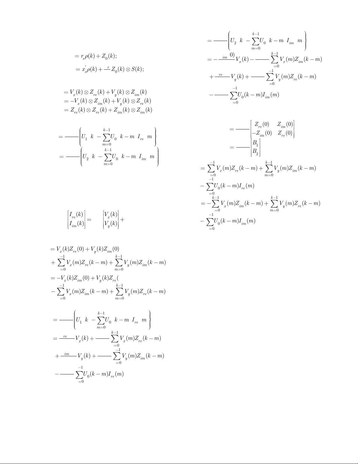
> REPLACE THI S LINE WIT H YOUR PAPE R IDENTI FICATION NUMBER (DOUB LE -CLICK HERE TO E DIT) < 1 Abstract — The Differ ential Tran sformation (DT) m ethod has demonstrated its potential in speeding up power system time-domain simulati on by our previous w ork. This letter further derives DT s about a motor load model and proves th at t he nonlinear current injection equation about a motor load can be transformed into a linear equation by means o f DT . Index Terms — Differential algebraic equation s; differen ti al transformation; dynamic simulation; motor load. I. I NTRODUCTION ifferential tran sformation (DT) method is a pro mising approach for power s ystem dynamic si mulation. I t i s introduced to power s ystem field in our recent work a nd has proved to b e effective to solve bo th the ordinar y differential equation (ODE ) model [1 ] and the differential algebr aic equation (DAE) m odel [2]. Fo r a DAE model w ith synchron ous generators and ZIP load m od els, no nlinear current injection equations were proved to satisf y a for ma ll y linear equation after DT, which is an important proper ty and has enabled a highly efficient algorith m to sol ve the DAE model without nu merical iterations . This letter f urther derives DT s about a m otor load m od el and proves that, the nonlinear current in jection equ at ion with a motor load model ca n b e transfor med into a formally lin ear equation after DT . T his demonstrates the effective ness of the DT method when applied to d ynamic load models. II. L INEAR R ELATI ONSHIP OF THE M OTO R L OAD M OD EL AFTER D IFF ER ENTIAL T RANSFORMA TION Th e Differential Transformation ( DT ) method was introduced to the power system field in [1]. A detailed introduction of t he DT method and the transfor mation rules fo r various ge neric nonli near func tions in power system models are provided in [ 1]-[2]. A. DTs o f the Motor Loa d Model A 3 rd ord er motor load model [3]-[5 ] is given b y a set of DAEs in (1)-(2), where s , v re ’, v im ’ are state variab les, meaning the m otor slip, the real and i maginary part of the tr ansient voltages ; i re and i m are the real and i maginary p art of the cu rrent This wor k was supported in part by the ERC Program o f the NSF and DOE under NSF G rant EEC-1041877 an d in part by NSF Grant ECCS-1610025. Y. L iu and K. Sun are with the Dep artment of EECS, University of Tennessee , Knoxville, TN 37996 USA (e-mail: yliu161@vol s.utk.edu , kaisun@utk.edu ). injections; v x and v y ar e the real and imaginary par t o f the terminal bus voltages; a nd the r emaining are para meters . 2 ' ' 1 1 1 ' ' ' ' ' ' ' ' 1 () 2 (( ) ) (( ) ) re re i m i m r re s s s i m re s i m r r i m s s s re i m s re r s a s b s c v i v i H r v w x x i v w s v x r v w x x i v w s v x (1 ) 2 2 2 2 2 ' 2 ' ' 2 2 2 2 2 2 , , w h e re ( ) ( ) ; x r e y i m x i m y r e re i m re i m r e i m r s s r s s r re s i m s r r r r r v z v z v z v z i i z z z z r x x r x x x z r z x s r r x s r x s (2) The DT of the differential equation (1) is given in (3), which is d erived following the si milar procedure in [1] with details omitted . 1 1 1 '' ' ' ' ' ' ' ' ' 1 ( 1 ) ( 1 ) ( ( ) ( ) ( ) ( ) 2 ( ) ( ) ( ) ( )) ( 1 ) ( 1 ) (( ) ( ) ( )) ( ) ( ) ( 1 ) ( 1 ) (( ) ( ) ( )) ( ) ( ) r e r e i m i m r r e s s s i m r e r s i m r i m s s s r e i m r s r e k S k a S k S k b S k c k H V k I k V k I k r k V k w x x I k V k x w S k V k r k V k w x x I k V k x w S k V k (3) To d erive the DT o f the algebraic current injectio n equation (2) , denote intermediate varia bles z 0 , z 1 , u 0 , u 1 and u 2 in (4)-(5). 2 ' 0 1 2 2 2 1 ( ) r s s rr r x x z z z r x s (4) 22 0 1 2 re i m x re y i m x i m y re u z z u v z v z u v z v z (5) First, DTs of z 0 and z 1 are given in (6). 1 2' 0 1 0 1 0 22 1 1 ( ) ( ) ( ) (0 ) ( ) ( ) ( ) ( ) k r s s m rr Z k r x x k Z k m Z m Z Z k r k x S k S k (6) Dif ferential T ransformation of a Motor Load Model for T ime-Domain Simulation Yang Liu, Student Memb er , IEEE , Kai S un, Senior Me mber, IEEE D > REPLACE THI S LINE WIT H YOUR PAPE R IDENTI FICATION NUMBER (DOUB LE -CLICK HERE TO E DIT) < 2 T he n, DTs of z re and z im are given in ( 7). 0 ' 0 ( ) ( ) ( ); ( ) ( ) ( ) ( ); re s r im s r Z k r k Z k x Z k x k Z k S k r (7) Thus, DTs o f u 0 , u 1 and u 2 are given in (8). 1 2 0 ( ) ( ) ( ) ( ) ( ) ( ) ( ) ( ) ( ) ( ) ( ) ( ) ( ) ( ) ( ) x r e y im x im y r e r e r e im im U k V k Z k V k Z k U k V k Z k V k Z k U k Z k Z k Z k Z k (8) Finally, DTs of the c urrent injectio n equation (2) is given: 1 10 0 0 1 20 0 0 1 () (0 ) 1 () (0 ) k re re m k im i m m I k U k U k m I m U I k U k U k m I m U (9) B. Linea r Relationsh ip Between Curr en t Injectio ns and Bus Voltages a fter DT Proposition : T he transformed current injection e quation ( 9) satisfi es a formally linear eq uation in ( 10 ). ( ) ( ) ( ) ( ) r e x i m y I k V k I k V k mm AB ( 10 ) Proof : Rewrite U 1 ( k ) and U 2 ( k ) in (8 ) as ( 11 )-( 12 ). 1 11 00 ( ) ( ) ( 0 ) ( ) ( 0 ) ( ) ( ) ( ) ( ) x r e y im k k x r e y im m m U k V k Z V k Z V m Z k m V m Z k m ( 11 ) 2 11 00 ( ) ( ) ( 0 ) ( ) ( 0 ) ( ) ( ) ( ) ( ) x im y r e k k x im y r e m m U k V k Z V k Z V m Z k m V m Z k m ( 12 ) Then (9) is written as ( 13 )-( 14 ). 1 10 0 0 1 0 00 1 0 00 1 0 0 0 1 () (0 ) (0 ) 1 ( ) ( ) ( ) (0 ) (0 ) (0 ) 1 ( ) ( ) ( ) (0 ) (0 ) 1 ( ) ( ) (0 ) k re r e m k re x x r e m k im y y i m m k re m I k U k U k m I m U Z V k V m Z k m UU Z V k V m Z k m UU U k m I m U ( 13 ) 1 20 0 0 1 0 00 1 0 00 1 0 0 0 1 () (0 ) ( 0 ) 1 ( ) ( ) ( ) (0 ) (0 ) (0 ) 1 ( ) ( ) ( ) (0 ) (0 ) 1 ( ) ( ) (0 ) k im i m m k im x x i m m k re y y r e m k im m I k U k U k m I m U Z V k V m Z k m UU Z V k V m Z k m UU U k m I m U ( 14 ) Finally, b y defining A m and B m in ( 15 ) w it h B 1 and B 2 defined in ( 16 ), the linear relationship ( 10 ) is satisfied. 0 1 2 0 ( 0 ) ( 0 ) 1 ( 0 ) ( 0 ) (0 ) 1 (0 ) re i m i m re ZZ ZZ U B B U m m A B ( 15 ) 11 1 00 1 0 0 11 2 00 1 0 0 ( ) ( ) ( ) ( ) ( ) ( ) ( ) ( ) ( ) ( ) ( ) ( ) k k x re y i m m m k re m kk x i m y re m m k im m B V m Z k m V m Z k m U k m I m B V m Z k m V m Z k m U k m I m ( 16 ) III. C ONCLUSION This letter extends the linear r elationship in [2 ] to the motor load model. It is pro ved that the nonlinear current injection equation of a m o tor load m o del also satis fies a linear relationship. This d emonstrates the ad aptability of the DT me thod to other types of load models. R EFERENCES [1] Y. L iu , K . Sun, R. Yao, B. W ang, "Po wer sy st em time do main simulation using a differential transformation method," IEEE Trans. Power Syst. , in press. [2] Y. Liu, K. Sun, " Solving P ower System Diffe rentia l Alge braic Equations Using Differe ntial Transformatio n ," arXiv:190 3.00935 , 2 019 . [3] P. Kundur, N. J. Ba lu , M. G. Lauby, Po wer system stability and control . McGraw -hill New York, 1994. [4] F. Milano, Power system modelling and scripting . Springer Science & Business Media, 2 010. [5] B. Wang, N. Du an, K. Sun, “A Time -Power Series Based Semi-A nalytical Approach for Power System Simulatio n,” IEEE Trans. Power Syst. , vol . 34, No. 2, pp. 84 1-851, March 20 19
Original Paper
Loading high-quality paper...
Comments & Academic Discussion
Loading comments...
Leave a Comment