Long-Duration Fully Autonomous Operation of Rotorcraft Unmanned Aerial Systems for Remote-Sensing Data Acquisition
Recent applications of unmanned aerial systems (UAS) to precision agriculture have shown increased ease and efficiency in data collection at precise remote locations. However, further enhancement of the field requires operation over long periods of t…
Authors: Danylo Malyuta, Christian Brommer, Daniel Hentzen
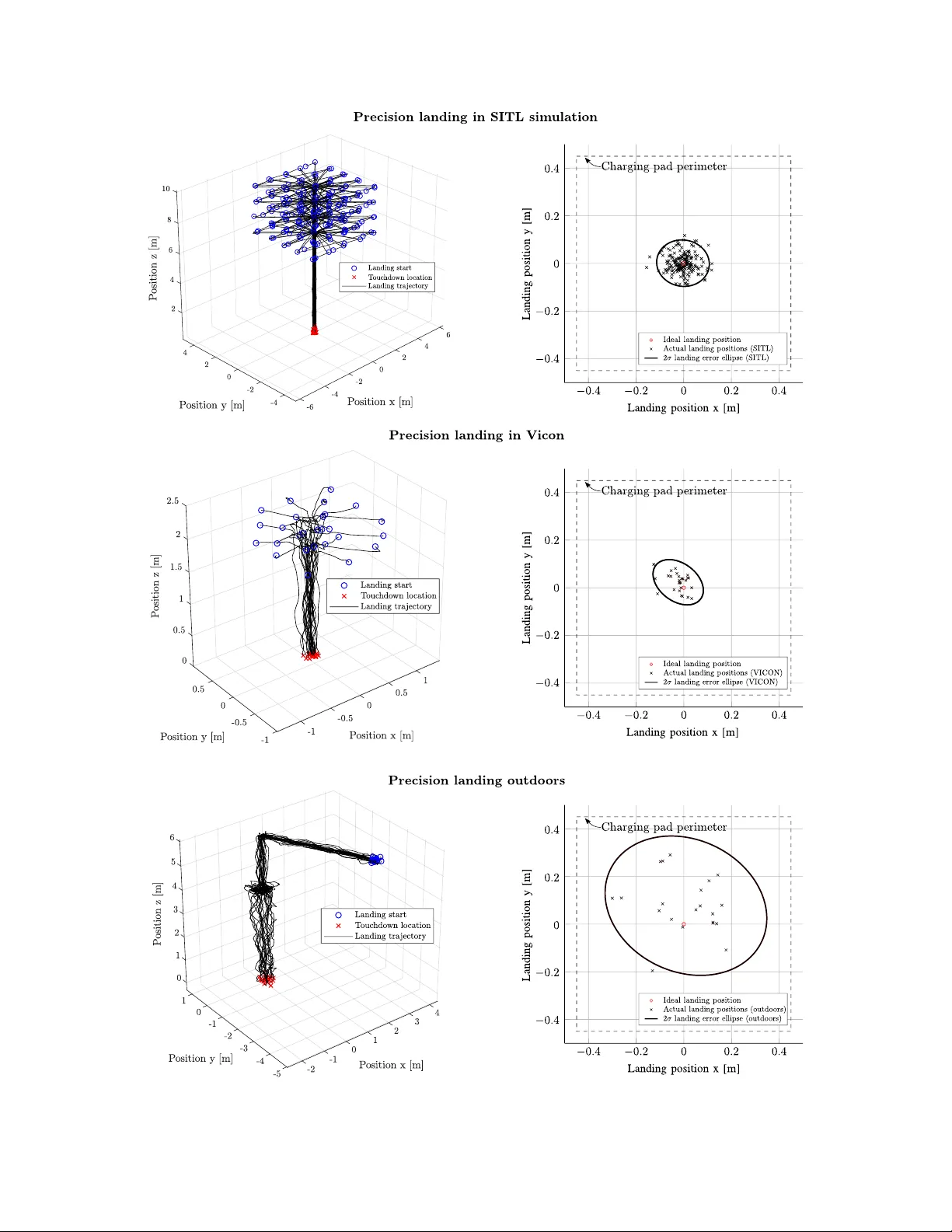
Long-Duration F ully Autonomous Op eration of Rotorcraft UAS for Remote-Sensing Data Acquisition Dan ylo Malyuta Autonomous Con trol Lab Univ ersity of W ashington Seattle, W A 98195 danylo@uw.edu Christian Brommer Con trol of Netw ork ed Systems Group Alp en-Adria-Univ ersit¨ at Klagenfurt Klagenfurt, Austria 9020 christian.brommer@ieee.org Daniel Hen tzen Jet Propulsion Lab oratory California Institute of T echnology P asadena, CA 91109-8099 daniel.r.hentzen@jpl.nasa.gov Thomas Stastn y Autonomous Systems Lab ETH Z ¨ uric h Z ¨ uric h, Switzerland 8092 thomas.stastny@mavt.ethz.ch Roland Siegw art Autonomous Systems Lab ETH Z ¨ uric h Z ¨ uric h, Switzerland 8092 rsiegwart@ethz.ch Roland Bro c k ers Jet Propulsion Lab oratory California Institute of T echnology P asadena, CA 91109-8099 brockers@jpl.nasa.gov Abstract Recen t applications of unmanned aerial systems (UAS) to precision agriculture ha ve shown increased ease and efficiency in data collection at precise remote lo cations. Ho wev er, further enhancemen t of the field requires operation o ver long p erio ds of time, e.g. da ys or w eeks. This has so far b een impractical due to the limited flight times of such platforms and the requiremen t of h umans in the loop for op eration. T o o vercome these limitations, we prop ose a fully autonomous rotorcraft UAS that is capable of p erforming rep eated flights for long-term observ ation missions without any h uman interv en tion. W e address t w o key tec hnologies that are critical for such a system: full platform autonomy to enable mission execution indep endently from h uman op erators and the ability of vision-based precision landing on a rec harging station for automated energy replenishment. High-level autonomous decision making is implemented as a hierarch y of master and slav e state machines. Vision- based precision landing is enabled by estimating the landing pad’s p ose using a bundle of AprilT ag fiducials configured for detection from a wide range of altitudes. W e provide an extensiv e ev aluation of the landing pad pose estimation accuracy as a function of the bundle’s geometry . The functionality of the complete system is demonstrated through tw o indo or experiments with a duration of 11 and 10.6 hours, and one outdo or exp eriment with a duration of 4 hours. The UAS executed 16, 48 and 22 flights resp ectively during these exp eriments. In the outdo or exp eriment, the ratio b etw een flying to collect data and c harging was 1 to 10, whic h is similar to past w ork in this domain. All flights w ere fully autonomous with no h uman in the loop. T o our b est knowledge this is the first researc h publication ab out the long-term outdo or op eration of a quadrotor system with no human in teraction. 1 In tro duction 1.1 Motiv ation The F oo d and Agriculture Organization of the United Nations predicts that foo d pro duction will hav e to increase by 70 p ercent b y the year 2050 in order to feed a pro jected additional 2.2 billion p eople (F o o d and Agriculture Organization of the United Nations, 2009). Precision agriculture, also known as smart farming, is a data-driv en approac h that helps to address this challenge b y using sensing tec hnology to increase farming efficiency . Data is collected for v ariables like plant and animal health, crop yields, organic matter conten t, moisture, nitrogen and pH levels. T o complemen t sensors moun ted on farming v ehicles, fixed- wing and rotorcraft Unmanned Aerial Systems (UAS) can be equipped with RGB, thermal and h yp ersp ectral cameras and flo wn o v er fields in order to create cost-effective and on-demand orthomosaic maps of bioph ysical parameters. The market for such robots is pro jected to b e the second-largest in the commercial drone sector (Goldman Sac hs, 2017). Rotorcraft UAS are ideal assets for deploying sensors and instruments in a 3D en vironment. Because they can ho ver and fly slowly , rotorcraft enable pin-p oint data gathering and can b e op erated in dense environmen ts suc h as under tree canopies that are inaccessible to traditional fixed-wing platforms. In the agricultural domain, an imp ortant application is the rep eated acquisition of the same target to capture changes in en vironmental prop erties such as plant water usage ov er the diurnal cycle. This is of increasing imp ortance for ecosystem monitoring applications where accurate measuremen ts of plant health parameters are desired do wn to leaf-level resolution of individual plants. Figure 1: Example deploymen t of a hexacopter UAS (a) with a hypersp ectral camera (b) to collect data for ND VI calculation with centimeter accuracy (c). The autonomy engine in this pap er can b e deploy ed on such a system as a future application. T o v alidate the feasibility of UAS remote sensing of relev an t data at high spatial resolutions, extensive data acquisition trials were carried out in collab oration with NASA’s Jet Propulsion Lab oratory environmen tal scien tists. Figures 1a and 1b show a hexarotor with a six-band visible and near-infrared (VNIR) camera and a thermal infrared camera payload that was used during sev eral campaigns at the W est Side Research and Extension Center (WSREC) at Fiv e Poin ts, California, to capture the diurnal cycle of plant water usage. Figure 1c illustrates a stitc hed map of the normalized difference v egetation index (NDVI) as an example data pro duct of one flight. The map’s pixel resolution of approximately 5 cm is b eyond what can b e curren tly ac hieved with orbital or traditional airb orne instruments. The autonom y engine developed in this pap er can b e deplo yed on such a quadrotor as a p otential future application. 1.2 Con tributions Because the typical flight endurance of a quadrotor system with payload is relatively short (t ypically 10- 20 min), long-term op eration currently requires humans in the lo op for energy replenishment (e.g. battery c harging). This makes con tinuous observ ations o ver long p erio ds of time impractical. T o solve this issue, w e prop ose a system that is capable of fully autonomous rep eated mission execution, including automated rec harging to replenish its batteries after a data collection flight is completed. Our main contribution is the dev elopmen t and outdo or deploymen t of a high-lev el autonomy engine that is executed on-board the UAS and which implements the capability of robust fully autonomous repeated data acquisition. This includes flight control for take-off and landing, GPS-inertial state estimation, system health monitoring including the execution of emergency b ehaviors, recharging and mission data handling. Once the autonomy engine is started, the system has the logic and softw are-hardware interfaces necess ary to op erate indefinitely without h umans in the lo op. The system is nov el by b eing human-indep endent and op er ating outdo ors . T o the b est of our kno wledge, there ha ve been no publications to date on quadrotor-type UAS platforms capable of autonomous recharging whic h hav e b een flown outdo ors for extended perio ds of time. Hence, prior w ork that demonstrates UAS rec harging has relied on the idealistic state estimation accuracy offered b y indo or motion capture systems. Since GPS-only lo calization is not sufficiently accurate for precision landing on a c harging pad, our work augmen ts the sensor suite with a monocular camera. In this con text, we present an extensiv e analysis seeking to find a landing pad fiducial mark er lay out that maximizes landing accuracy . 1.3 Notation The following notation is used throughout the rep ort. Scalars are low ercase (e.g. a ), v ectors are low ercase b old (e.g. a ) and matrices are upp ercase (e.g. A ). The p osition of frame { b } in frame { a } is written p b a . The quaternion active rotation from { a } to { b } is written q b a and the corresp onding rotation matrix is C q b a . The homogeneous transformation matrix T ab tak es homogeneous vectors in { b } to { a } . Raw measurement quan tities carry a hat, e.g. ˆ p b a , while filtered quan tities carry a tilde, e.g. ˜ p b a . 1.4 Outline This pap er is organized as follows. Section 2 surveys existing work on long-duration autonomy and vision- based landing, the tw o key enabling technologies for our system. The hardware and softw are architectures are then describ ed in Section 3. Sections 4, 5 and 6 detail the navigation, guidance and control subsystems resp ectiv ely whic h enable the UAS to execute fligh t tasks. The autonom y engine itself is presented in Section 7. Field tests with the system in environmen ts of increasing complexity , up to real world conditions, are then giv en in Section 8, follow ed by a discussion of future work and conclusion in Sections 9 and 10. 2 Related W ork In this section we review related work in our tw o main areas of contribution, the ability to replenish energy for long-duration autonom y and vision-based precision landing. 2.1 Long-duration Autonomy Sev eral rotorcraft UAS that are capable of autonomous, long-duration mission execution in b enign indo or (VICON) environmen ts hav e previously app eared in literature. F o cusing on the recharging solution to extend individual platform fligh t time and a multi-agen t scheme for constant op eration, impressive op eration times ha ve b een demonstrated ((V alenti et al., 2007): 24 h single vehi cle exp eriment; (Mulgaonk ar and Kumar, 2014): 9.5 h with m ultiple v ehicles). Recharging metho ds v ary from wireless c harging (Aldhaher et al., 2017) to con tact-based c harging pads (Mulgaonk ar and Kumar, 2014) to battery sw ap systems (T oksoz et al., 2011; Suzuki et al., 2011). While wireless charging offers the most flexibility since no physical contact has to b e made, charging currents are lo w resulting in excessiv ely long charging times and are hence not an option for quic k redeploymen t. How ev er, in teresting results hav e b een sho wn in (Aldhaher et al., 2017) demonstrating wireless p ow ering of a 35 g/10 W micro drone in hov er flight. On the other end of the sp ectrum, battery sw ap systems offer immediate redeploymen t of a UAS, but require sophisticated mechanisms to b e able to hot swap a battery , and a p o ol of charged batteries that are readily a v ailable. This mak es such systems less attractiv e for maintenance free and cost effective long-term op eration. 2.2 Vision-based Landing Our work uses a down w ard-facing mono cular camera to estimate the p ose of the landing pad in the world frame using AprilT ag visual fiducial markers (W ang and Olson, 2016). W e believe that a monocular camera is the c heap est, most light w eigh t and p ow er efficien t sensor choice. Alternativ ely , GPS and R TK-GPS systems suffer from precision degradation and signal loss in o ccluded urban or can y on en vironmen ts (Jin et al., 2016). Laser range finder systems are hea vy and consume considerable amounts of energy . Last but not least, stereo camera setups ha ve limited range as a function of their baseline versus vehicle-to-pad distance. Sev eral landing approac hes exist in literature for lab eled and unlab eled landing sites. (Y ang et al., 2012) presen t a mono cular visual landing metho d based on estimating the 6 DOF p ose of a circled H marker. The same authors extend this work to enable autonomous landing site search b y using a scale-corrected PT AM algorithm (Klein and Murray , 2007) and relax the landing site structure to an arbitrary but feature- ric h image that is matc hed using the ORB algorithm (Rublee et al., 2011). (F orster et al., 2014; F orster et al., 2015) use SV O to estimate motion from a do wnfacing mono cular camera to build a probabilistic 2 dimensional elev ation map of unstructured terrain and to detect safe landing spots based on a score function. (Bro c kers et al., 2011; Bro ck ers et al., 2012) develop a fully self-contained visual landing navigation pip eline using a single camera. With application to landing in urban environmen ts, the planar character of a ro oftop is leveraged to p erform landing site detection via a planar homography decomp osition using RANSAC to distinguish the ground and elev ated landing surface planes. Ho wev er, landing algorithms whic h build elev ation maps and p erform generic landing sp ot detection trade their robustness for the abilit y to land in unlab eled en vironments. By placing visual fiducial markers at or near the landing zone, one can use visual fiducial detector algorithms to estimate the landing pad p ose more reliably , i.e. with less false p ositives and negatives. Curren tly one of the most p opular visual fiducial detectors and patterns is the AprilT ag algorithm (Olson, 2011) which is renowned for its sp eed, robustness and extremely low false positive detection rates. The algorithm w as up dated b y (W ang and Olson, 2016) to further impro v e computational efficiency and to enable the detection of smaller tags. AprilT ag has b een applied multiple times for MA V landing (Brommer et al., 2018; Ling, 2014; Kyristsis et al., 2016; Boro w czyk et al., 2017; Chav es et al., 2015). Similar visual fiducials are seen around the landing zones of b oth Amazon and Go ogle delivery drones (Amazon, 2016; Vincen t, 2017) as well as of some surveying drones (Wingtra, 2017). Our approach is the same as that of (Brommer et al., 2018). W e improv e ov er (Ling, 2014; Kyristsis et al., 2016) by using a bundle of several tags for impro v ed landing pad p ose measurement accuracy . (Boro wczyk et al., 2017; Chav es et al., 2015) app ear to also use a tag bundle, how ev er they deal with a moving landing platform and feed individual tag p ose detections into a Kalman filter. Our approach is to use a p ersp ectiv e- n -p oint solution to obtain a single p ose measuremen t using all tags at once. After obtaining ra w tag pose estimates from the AprilT ag detector, our approach uses a recursiv e least squares (RLS) filter to obtain a common tag bundle p ose estimate. A relev ant previous work on this topic is (Nissler et al., 2016) in which a particle filter is applied to raw tag detections and R LS is compared to RANSA C for bundle p ose estimation. Because the demonstrated accuracy impro vemen t is marginal (ab out 1 cm in mean p osition and negligible in mean attitude) and RANSAC has disadv antages lik e ad ho c threshold settings and a non-deterministic run time, we prefer RLS for its simplicit y . Nevertheless, RANSA C and its more adv anced v ariations (Hast et al., 2013) can be substituted into our implementation. Other work in vestigated fusing tag measuremen ts in RGB space with a depth comp onent (Jin et al., 2017) with impressive gains in accuracy . One can imagine this approac h b enefiting landing accuracy at lo w altitudes, ho wev er down w ard-facing stereo camera moun ting on drones raises several concerns like weigh t, vibration effects and space av ailability . Our approac h, how ev er, is not limited to AprilT ags, which can b e substituted or com bined with other Figure 2: Autonomous UAS data acquisition cycle. 1: the v ehicle is placed on the landing station to start the op eration. 2: takeoff to safe altitude. 3: mission execution. 4: vision-based precision landing. 5: recharging and data do wnloading. mark ers for sp ecific applications. A v ast num b er of markers is av ailable targeting different use-cases (Jin et al., 2016; Y ang et al., 2012; Fiala, 2005; Olson, 2011). P atterns include letters, circles, concentric circles and/or p olygons, letters, 2 dimensional barco des and sp ecial patterns based on top ological (Bencina et al., 2005), detection range maximizing (Xu and Dudek, 2011) and blurring/o cclusion robustness considerations (Bergamasco et al., 2016). 3 System Ov erview Our system consists of t w o ma jor components: the aerial v ehicle with its on-board autonom y soft w are (autonom y engine) and a landing station whic h integrates a charging pad, a base station computer for do wnloading data, and a wireless router for communication with the UAS while landed. T o deploy the system, a user connects the landing station to a p ow er outlet and places the UAS on top of the landing surface as sho wn in Figures 2 and 3. After providing a w aypoint based mission profile, a start command commences the op eration of the system. All actions of the UAS from then on are fully autonomous with no human inv olv ement. The autonomy engine implemen ts v arious mission sp ecific b eha viors to guide the v ehicle, including health monitoring and emergency resp onse that are explained in Section 7. Figure 3: Landing station with visual bundle (left), c harging pad (righ t), and UAS. The recharging pro cess starts automatically when the quadrotor mak es contact with the 90 × 90 cm charging surface. 1 (Na vigation camera) USB 2.0 mvBlueF OXMLC200wG downfacing camera w ith a 100 ◦ F OV lens 2 (P ayload) FLIR Ax5-series thermal camera 3 5 GHz dual band WiFi mo dule 4 T rimble BD930-UHF GPS receiv er 5 3-axis magnetometer 6 UHF an tenna 7 GPS an tenna 8 R C receiver 9 Leg c harging contacts 10 CR C C6S LiPo balance charger 11 Odroid XU4 na vigation computer 12 3S1P 6200 mAh LiP o battery holder 13 AscT ec AutoPilot Board 14 AscT ec Po w er Board Figure 4: Hardw are elements on our test UAS (mo dified AscT ec Pelican). Figure 5: On-b oard hardw are arc hitecture and information flow. Solid and dashed lines represent information and energy flo ws resp ectively . Comm unication proto cols are lab elled where known. 3.1 Hardw are Architecture Figure 4 illustrates the main hardw are elements of our test UAS. Figure 5 displa ys the quadrotor on-b oard hardw are architecture. Solid lines represent information flow and are lab elled whenev er the communication proto col is known, and dashed lines represent energy flow. The gray blocks in Figure 5 lab el the comp onen ts that host the fligh t softw are developed in this work. T o minimize rec harging time, we use a contact-based, commercially av ailable charging solution (Skysense, 2018) to provide ample charging current to the on-board charging electronics. The c harging pad consists of an arra y of individual contact patches that cov er a 90 × 90 cm flat area. Charging is triggered b y the c harging pad electronics once contact to the charger on-board the UAS is made via leg contacts. Charging status is monitored online by the autonom y engine, which prepares for the next flight once the battery is sufficien tly charged. While landed, the vehicle connects to the base station computer via WiFi to downlink mission data and to receiv e even tually up dated mission plans (e.g. mission-end command from a user). 3.2 Soft w are Ar c hitecture Figure 6 illustrates the full autonomy system as an information flow diagram. Sensors feed information to the Single Sensor F usion (SSF) state estimator (W eiss et al., 2012), mo dified to handle multiple sensors, and to the visual landing navigation subsystems. These supply the control, guidance and autonomy algorithms Figure 6: Sensor and soft ware system blo ck diagram. Gray blo cks are part of the softw are subsystem. with na vigational information necessary for stabilization, tra jectory generation and state machine transitions. The con trol subsystem is then resp onsible for tra jectory tracking and desired motor sp eed computation. 3.3 Mission Architecture The UAS executes a mission profile depicted in Figure 2. Before each take-off, the system initializes the on-b oard state estimator and passes a series of pre-flight chec ks that include testing for an adequate battery v oltage level and motor nominal p erformance. The vehicle then p erforms a take-off maneuver by issuing a vertical velocity command to its lo w-level velocity controller to climb to an initial altitude. Once a safe altitude is reached, the mission execution module within the autonom y engine takes ov er. A mission is defined as a set of wa yp oin ts connected b y individual tra jectory segmen ts that are calculated using p olynomial tra jectories follo wing the approac h of (Mellinger and Kumar, 2011; Ric hter et al., 2016). A tra jectory trac king mo dule plays the mission tra jectory forward in time by issuing p osition references to the low-lev el p osition controller. During mission execution, a system health observer monitors all critical comp onents of the UAS and issues emergency messages to the autonomy engine to implemen t fail-safe behaviors (e.g. return-to-home, emergency-landing on lo w battery or state estimation failure). After the mission is completed, the UAS returns to the vicinit y of the landing station using the recorded GPS p osition of the take-off lo cation. Our vision-based landing navigation algorithm then detects the landing station AprilT ag fiducials with its downfacing camera. Once the landing lo cation is accurately detected, a landing maneuver is executed by first hov ering ov er the landing lo cation and then issuing a tra jectory with a fixed descent velocity that passes through the center of the c harging pad surface. T ouc hdown is triggered Figure 7: Vision-based landing navigation blo ck diagram. A do wnfacing camera feeds images to a radial undistorter. AprilT ag markers are detected in the resulting images and their p ose is jointly estimated via a p ersp ectiv e- n -p oint solution. An RLS estimator smo othens the resulting signal based on a curren t estimate of the measuremen t v ariance. b y detecting zero velocity b elow a minimum altitude threshold. 4 Na vigation The navigation subsystem is resp onsible for estimating the UAS state and the landing pad p ose in the world frame. The landing pad pose estimation is designed to pro vide a sufficiently accurate pose estimate to b e able to land on a 90 × 90 cm surface. The vehicle p ose estimator is designed to work in an outdo or environmen t suc h as a crop field. 4.1 Visual Landing Navigation Figure 7 details our landing site detection algorithm. The downfacing camera feeds a distorted 752 × 480 px gra yscale image, I raw , into the image undistorter. The latter remo ves radial distortion in the image via the ideal fish-eye lens mo del (Dev ernay and F augeras, 2001), pro ducing the un-distorted image I pin assumed to b e pro duced by a pinhole camera with calibration matrix K ∈ R 3 × 3 . The unmo dified AprilT ag 2 implemen- tation (APRIL Lab oratory , 2016) identifies AprilT ag markers in I pin and for each tag with ID i pro duces a homography matrix H i ∈ R 3 × 3 . Assuming that at least one tag is detected, a p ersp ective- n -point solver (Op enCV, 2017) pro duces an AprilT ag bundle p ose measurement ˆ p l w , ˆ q l w of the landing pad in the world frame. This measurement is passed to a recursive least squares (RLS) estimator to output ˜ p l w and ˜ q l,ya w w where the latter is a pure y a w quaternion b ecause we assume the landing pad to b e level. The RLS outputs are then used for landing navigation. The algorithm is executed on a single core of an Odroid XU4, except for the AprilT ag 2 detector which runs on t wo cores, and achiev es a measuremen t frequency of approximately 7 Hz as sho wn in Figure 8. Estimation of the landing pad p ose using a tag bundle has several adv an tages. First, by pro viding more Figure 8: Landing bundle p ose measuremen t frequency . The median is 6.5 Hz. Figure 9: Rigid b o dy transforms from each tag’s lo cal frame to the landing pad frame. Generic tags i , j and k are shown. p oin ts to compute the homography matrix, the landing pad p ose measurement b ecomes more accurate and robust to effects lik e tag corner detection error. F urthermore, a bundle can be composed of larger and smaller tags suc h that it is visible from a wide range of altitudes (see Section 8.1.1). 4.1.1 Bundle Calibrati on T o compute ˆ p l w and ˆ q l w , the transformation matrix from each tag to the landing pad frame must b e known. This is shown in Figure 9 and the computation of these transforms is called landing bundle calibration. Because the landing pad p ose directly affects the desired UAS landing p ose (see Section 4.1.2), calibration is crucial for successful system op eration. Our calibration approach is to place the UAS do wnfacing camera with the landing bundle visible, forming a rigid b o dy transform triad as sho wn in Figure 10. F or the calibration pro cess, a “master” AprilT ag mark er is placed at the same p osition and y aw as desired for the UAS and the do wnfacing camera resp ectively during landing (see Figure 11). The unkno wn calibration transform T lt i is giv en by: T lt i = T − 1 cm T ct i . (1) Figure 10: Rigid transform triad formed during the calibration pro cess betw een the camera frame, the master tag/landing pad frame and the i -th tag frame. Ho wev er, every standalone tag p ose measurement con tains error due to effects from image blur, pixelation, etc. The result of single-measurement computation (1) is therefore not reliable. F or this reason, a statistical approac h is taken and a sequence of several hundred ˆ T ct i and ˆ T cm is collected. These measurements are then combined into a geometric median p osition and a mean quaternion attitude of each tag relative to the landing pad frame. Computational details are pro vided in (Malyuta, 2018). 4.1.2 Landing Ali gnmen t The UAS can align itself with the landing pad by using landing pad p ose estimate ˜ p l w and ˜ q l,ya w w . F or this purp ose, consider the alignment scenario depicted in Figure 11. The desired attitude of the camera is to lo ok straight down at the landing pad frame, hence q l c des corresp onds to a 180 ◦ rotation ab out the x -axis. As shown in Figure 11, we hav e all the elements necessary to compute the desired b o dy p ose such that the UAS is center-aligned with the landing frame and the camera is facing do wn with a ya w implicitly defined b y the master tag during the calibration step of Section 4.1.1: q align = ( q l c des ⊗ ˜ q c b ) − 1 ⊗ ˜ q l,ya w w , (2) p align = ˜ p l w + ( h align − ˜ p l w,z ) e z , (3) Figure 11: F rame setup for pad-aligned b o dy frame p ose computation during the initial part of the landing phase. where h align is the desired altitude ab o v e the landing pad prior to final descent and e z = (0 , 0 , 1). Once aligned, the landing autopilot descends the UAS un til touchdo wn as describ ed in Section 7.5. 4.2 V ehicle Pose Estimation The state estimation subsystem computes the v ehicle p ose to b e used for guidance and control. F or this purp ose the SSF algorithm (W eiss et al., 2012) is extended to fuse multiple sensors. In particular, we use an IMU, a GPS for position and velocity , a pressure sensor for impro ved height estimation, and a 3-axis magnetometer for ya w observ abilit y during hov er and constant v elo city flight. W e denote by { b } , { g } , { m } and { p } the b o dy (i.e. IMU), GPS, magnetometer and pressure sensor frames resp ectively and use the follo wing state vector: x state = ( p b w , v b w , q b w , b ω , b a | {z } Core state , p g b , q m b , m w , b p , p p b ) , (4) where b ω ∈ R 3 , b a ∈ R 3 and b p ∈ R are the gyroscop e, accelerometer and pressure sensor biases and m w ∈ R 3 is a normalized magnetic field vector. The core state p ortion of (4) together with the raw gyroscop e b o dy rate measurement is used for control and guidance. During the landing phase, the landing pad p ose estimate ˜ p l w and ˜ q l,ya w w is used to re-lo calize the landing pad in the world frame. This is necessary due to drift in the GPS sensor during long fligh ts. 5 Guidance The guidance subsystem is resp onsible for generating con trol reference signals with the aim of following a sp ecific tra jectory or arriving at a sp ecific destination (Grewal et al., 2007). This section describ es the guidance philosophy and main asp ects, while further computational details are pro vided in (Malyuta, 2018). The guidance subsystem is designed with the ob jectives of b eing computationally light weigh t and capable of generating predictable tra jectories that are dynamically feasible and that enable the UAS to explore an obstacle-free 3D volume via p oint-to-point constan t velocity segments. Among existing metho ds that mini- mize snap (Mellinger and Kumar, 2011; Rich ter et al., 2016; Burri et al., 2015; de Almeida and Akella, 2017), jerk (Mueller and D’Andrea, 2013; Mueller et al., 2015) and energy (A¸ cıkme¸ se and Plo en, 2007; Blackmore et al., 2010), our approach is to compute the tra jectories as fully constrained 9-th order p olynomials that are smo oth up to snap at their endp oints. This av oids online optimization and, in our exp erience, makes the planned tra jectory m uch more readily predictable than the other approaches. Figure 12: Illustration of a tra jectory and p olynomial interpolation p oints. All quadrotor tra jectories are comp osed of sequences of either segmen t 1 or 2. 5.1 T ra jectory Segments A mission is comprised of a sequence of tra jectory segments. As shown in Figure 12, there are tw o main t yp es of tra jectories. The first, a transfer tra jectory , interpolates all deriv ativ es up to snap smoothly b etw een an y t w o v alues in a fixed amount of time. The second, a mission tra jectory , is a set of constan t v elo cit y segmen ts b etw een user-defined w a yp oin ts where transitions b etw een different velocities are filleted by transfer tra jectories. Figure 13 shows a typical example of a generated wa ypoint mission, with the UAS b o dy frame sampled along its length. W e also provide the ability to hov er at any wa ypoint in the mission tra jectory , whic h o ccurs at the first and second to last wa yp oints in Figure 13. It can b e seen that the tra jectory consists mostly of constan t v elo city segments. Our approach ensures that these segmen ts b etw een user- defined w aypoints are straight, which is desirable for most remote sensing applications. 5.2 T ra jectory Sequencer The tra jectory sequencer aggregates individual tra jectory segmen ts in to a contin uous sequence of tra jectories. This is implemented as a doubly-linked list where each element stores the tra jectory segmen t, a timestamp and a type which is either single or cyclic where in the former case the tra jectory is flown only once and in the latter it is repeated un til being ab orted by other means such as a low battery charge flag. As describ ed in Figure 14b, we additionally provide a volatile element whic h enables executing one-time transfer tra jectories to correct for v ery large tra jectory tracking errors. Figure 13: An example wa ypoint tra jectory . Corresp onding UAS b o dy frame, magenta velocity and black acceleration are shown at 2 second time interv als. Bo dy frame attitude is obtained via the flat output to state map (Mellinger and Kumar, 2011). 6 Con trol W e use a three-stage cascaded control architecture shown in Figure 15 to track the reference tra jectories output b y the tra jectory sequencer. The stages are, from outer- to inner-most lo op: translation, attitude and b o dy rate controllers. A cascaded control ler has the adv an tage that inner lo ops provide faster disturbance rejection and reduce the effect of nonlinearities (Skogestad and Postleth waite, 2005), which is b eneficial for accurate trac king. The controller is executed on the AscT ec HLP as shown in Figure 5. The guidance subsystem forms the outermost lo op. It is executed at 20 Hz and outputs a reference p osition p ref , a reference velocity v ref , a reference ya w ψ ref and optionally a feed-forward acceleration a ff and feed- forw ard bo dy rates ω ff . All quan tities are obtainable from our polynomial tra jectories via differen tial flatness theory (Mellinger and Kumar, 2011). T ranslation control forms the next inner lo op and consists of a pre-filtered tw o degree of freedom PID con troller (Skogestad and Postleth w aite, 2005) which outputs a desired vehicle acceleration a ref . Since a ref defines a reference thrust vector, the translation controller may b e thought of as a thrust vector calculator. In order to prev ent excessiv e tilt of the UAS, we limit the thrust v ector to a 20 ◦ cone half-angle ab out the v ertical axis. T ranslation con trol lo op bandwidth is b etw een 1 and 2 rad/s. In the even t of a loss of state (a) A tra jectory sequence with a cyclic segmen t. F rom (1) to (2), the sequence is play ed forward until the cyclic segment is en tered. F rom (2) to (4), an arbitrary time ma y pass as each time that the cyclic elemen t is finished, it gets rewound. Therefore, cur- r ent nev er adv ances. In (5), the cyclic segment is ab orted to mov e to the next element. (b) An example with a v olatile elemen t. Betw een (1) and (2), a volatile transfer tra jectory is inserted. This pauses the original curr ent segmen t while the v olatile segment is track ed. In (3), the volatile ele- men t is finished. The list transitions back to the orig- inal element while the volatile element is remo ved. List ev aluation con tinues in (4). Figure 14: T ra jectory sequencing examples using a doubly-linked list which mov es the reference quadrotor state from one segment to the next in Figure 12. Partial fill with a gray background is used to illustrate time along eac h segment. Figure 15: Cascaded control lo op blo ck diagram with the following nested lo ops: guidance, translation, attitude and b o dy rates. T ranslation con trol generates a reference thrust vector, attitude control generates desired b o dy rates to achiev e it and b o dy rate control generates the desired motor thrusts. Motor control is p erformed b y AscT ec ESCs in op en lo op. estimation due to communication or sensor failure, a standby emergency landing controller can ov erride the translation controller and land the UAS by inducing a − 2 m/s vertical velocity in an op en-lo op fashion similar to (Mueller and D’Andrea, 2012; Lupashin et al., 2014). This even t can o ccur as a result of serial comm unication cable failure, for example. The attitude control forms the next inner lo op and tracks a ref and ψ ref b y generating a bo dy rate reference ω ref and a collective thrust reference T ref for the b o dy rate controller. Our implementation of the attitude con troller is based on the globally asymptotically stable and robust to measurement noise quaternion-based con trollers in tro duced in (Brescianini et al., 2013; F aessler et al., 2015). The attitude con trol lo op bandwidth is b et ween 5 and 10 rad/s. The b o dy rate controller forms the inner-most lo op of the cascaded flight control system. It tracks ω ref b y computing reference b o dy torques, following the feedback-linearizing control scheme presented in (F aessler et al., 2017). These along with T ref are then conv erted into individual reference motor thrusts f ref that are mapp ed to prop eller sp eeds via a full quadratic motor calibration map. Our controller uses a thrust saturation sc heme based on (F aessler et al., 2017) which prioritizes roll and pitch torques, which are the most imp ortan t ones for stability . The b o dy rate con trol lo op bandwidth is approximately 40 rad/s. 7 Autonom y Engine The autonomy engine subsystem implemen ts the logic for long-duration fully autonomous op eration with rep eated data acquisition fligh ts. 7.1 Arc hitecture Ov erview Figure 2 illustrates the ov erall concept of op eration for rep eated data acquisition. Eac h mission phase is implemen ted as a stand-alone state machine called an autopilot that executes the logic asso ciated with the phase whenev er it is activ ated via a Rob ot Op erating System (ROS) action interface. T o co ordinate calls to each autopilot, an additional ov erarching logic is implemented as a high-level master state machine. The hierarc hy of state machines and their interface to other ma jor subsystems is shown in Figure 16. All s tate mac hines are executed in parallel threads at a frequency of 20 Hz. Figure 16: Hierarc hy of master state mac hine and autopilots (gray) and other subsystems . The autopilots execute the logic asso ciated with the corresp onding mission phase and their execution is synchronized by the master to p erform a sp ecific mission profile. 7.2 Master State Machine The master state mac hine co ordinates calls to the phase-sp ecific autopilots and is illustrated in Figure 17. In con trast to the computation-heavy autopilots, the master p erforms no computations itself. Its sole resp on- sibilit y is to initiate even t-based state transitions. In the takeoff, mission, landing and emergency landing states the master state machine activ ates the appropriate autopilot and w aits for it to complete. If necessary , the master can also abort eac h autopilot in order to execute robust b ehaviors for cases like low battery c harge in flight or abnormal motor p erformance b efore takeoff. F or example, if battery charge anomalously drops to critical levels, the mission and landing actions can b e ab orted mid-execution to p erform an emergency landing action. 7.3 T akeoff Autopilot The takeoff autopilot takes the UAS from a motors-off state on the charging pad to a ho v er at a target tak eoff altitude. The pro cedure is illustrated in Figure 18a. In summary , after successfully v alidating motor nominal p erformance, re-initializing the state estimator after the prolonged charging phase and memorizing the curren t horizontal lo cation in p ermanent memory , the tak eoff autopilot commands a velocity-con trolled tak eoff that takes it from the initial p osition on the charging pad to a target altitude. Tw o parts of the takeoff pro cedure are of particular interest. The first is a motor nominal p erformance chec k whic h o ccurs prior to takeoff. Motors are spun at a low RPM, which is measured via zero crossing detection, and are verified to rotate within 400 RPM of the nominal v alue. T en attempts to pass this chec k are allow ed b efore the takeoff is ab orted. Our test flights had instances of this pro cedure saving the UAS e.g. when an I 2 C cable to one of the motors dislo dged. The next imp ortant part of the takeoff is saving the current Figure 17: Master state machine diagram. The master state mac hine parses mission even ts (e.g. battery status and touchdo wn detection) and co ordinates calls to the phase-sp ecific autopilots, but performs no computations itself. lo cation to a database in p ermanent memory . This gives the UAS knowledge of where to return to after the mission and also prev ents this information from b eing lost in case a softw are reset is required. 7.4 Mission Autopi lot The mission autopilot is responsible for executing the actual data acquisition mission as defined by the user in the form of individual wa ypoints and hov er times. The algorithm is illustrated in Figure 18b. The mission tra jectory is p erformed either once or is re-flown contin uously until an even t such as low battery charge requests the UAS to return to the ch arging pad. 7.5 Landing Autopilot The landing autopilot safely tak es the UAS from a hov ering state in the vicinity of the landing pad to a motors-off state on the c harging surface. The pro cedure is illustrated in Figure 18c. The first action is to c hec k if the landing pad is visible in the downfacing navigation camera image, i.e. if any AprilT ag in the bundle is detected. If not, the UAS executes the spiral grid search tra jectory until the landing bundle b ecomes visible. The vision-based landing navigation algorithm (Figure 7) then b ecomes activ ated. The (a) T ak eoff autopilot. This takes the UAS from a motors- off state on the charging pad to a hov er at a target takeoff altitude. (b) Mission autopilot. This executes the actual data ac- quisition mission by interfacing with the guidance sub- system (Section 5). (c) Landing autopilot. This takes the UAS from a hov er- ing state in the vicinit y of the landing pad to a motors-off state on the charging surface. (d) Emergency landing autopilot. This brings the UAS to a soft touchdo wn at its current lo cation when a criti- cally low battery even t o ccurs. Figure 18: Autopilot logic in flo wc hart representation. estimated y a w is used to align the vehicle attitude such that the camera p oints tow ards the visual markers, while the landing position estimate is used to align the v ehicle’s lateral p osition o v er the cen ter of the c harging pad. The vehicle then p erforms a constan t velocity descent until touchdo wn is detected based on 0.3 m heigh t and 0.1 m/s velocity thresholds: touc hdown = ( ˜ p b w,z − ˜ p l w,z ) < 0 . 3 ∧ | ˜ v b w,z | < 0 . 1 . (5) 7.6 Emergency Lander The emergency lander brings the UAS to a soft touchdo wn at its curren t location and is triggered in resp onse to a critically lo w battery voltage. Note that this is a differen t behavior from the emergency landing controller in Figure 15, which handles state estimation failure. The emergency lander logic is illustrated in Figure 18d. The algorithm descends the UAS with a mild v ertical velocity of 0.3 m/s until touchdo wn is detected based on a 0.1 m/s v elo city threshold: touc hdown = k ˜ v b w k 2 < 0 . 1 . (6) 8 Exp erimen tal Results The system was tested in four configurations of increasing complexity . These w ere softw are-in-the-lo op (SITL) simulation (F urrer et al., 2016), indo or tethered flights with VICON-based state estimation, outdo or tethered flights with GPS-based state estimation and outdo or free flights. SITL simulation allo ws for rapid testing and debugging by removing most logistic concerns and by making it easier to identify algorithmic errors due to the absence of real-world noise. Indo or test fligh ts under VICON allow to refine the guidance, con trol and autonom y subsystems indep endently of state estimation. Finally , outdo or flights v alidate that the system w orks in its real-world environmen t. 8.1 Vision-based Landing Accuracy T o design an AprilT ag marker bundle for lo calizing the landing pad as explained in Section 4.1, we first analyzed the detection accuracy in a stationary setting of the AprilT ag 2 algorithm for single tags at v arious observ ation distances using the downfacing camera that is deploy ed on our UAS (see Figure 4). Figure 19 shows the standard deviation of the distance estimate for v arious tag sizes and distances. F or a Figure 19: Distance estimation error of AprilT ag 2 detector for v arious tag sizes and heigh ts. F or a given tag size, accuracy decreases as distance increases. F or large enough distances, smaller tags cease to b e detected. Figure 20: Comparison of landing bundle height estimate with ground truth altitude during a test fligh t of the UAS ab o ve the landing station. Ground truth is provided by the R TK-GPS altitude reading. Figure 21: Landing bundle height error as a function of flight altitude. The error is approximately 0.32 m at the approac h height of 4 m and decreases to b elow 0.1 m in the final stage of descent. giv en tag size, the estimation accuracy decreases with increasing distance. Large tag sizes (48 cm, 60 cm) are not detected at distances b elow 2 m, while small tag sizes (10 cm, 15 cm, 20 cm) cease to b e detected ab o ve 4 m. F or an initial approach heigh t of 4 m, we selected a 48 cm tag for an exp ected 2 σ (i.e. 2 standard deviation) height estimation error of 4.5 cm and bundled it with three 15 cm tags for increased precision at lo wer altitudes, resulting in the bundle depicted in Figure 3 and the b ottom left of Figure 23. Figure 20 illustrates an exp eriment where the quadrotor was flown at v arious heights ab ov e the landing mark er bundle sho wn in Figure 3. The statistics for the error b etw een the heigh t estimate using the AprilT ag detector and the ground truth from R TK-GPS are plotted in Figure 21. At the approach height of 4 m the 2 σ height detection error is 0.32 m. The error decreases to b elow 0.1 m in the final stage of the descent. W e note that this estimation error v ariance is larger than for the individual tags in Figure 19. The increased error is most likely caused by image blur and latency effects due to the motion of the v ehicle and a lev er arm effect that amplifies p osition errors at the desired landing lo cation (the c harging pad center) as a result of angular errors in the AprilT ag detection. Section 8.1.1 provides a remedy to the lev er arm effect. Figure 22 illustrates the accuracy of autonomous landing in three environmen ts of increasing complexity . First, 200 landings were tested in SITL sim ulation with a random wind force a veraging 30 km/h mo deled as a random walk for the wind direction. The 2 σ landing error is 0.09 m (ma jor half-axis) and 0.08 m (minor half-axis). Because simulation uses the ground-truth UAS p ose for control, we ma y conclude that this is roughly the landing error that our con trol and landing na vigation algorithms are able to maintain in severe wind conditions. Next, the UAS p erformed 27 landings indo ors with VICON state estimation in near-optimal conditions. The resulting 2 σ landing error ellipse aggregates all detection and control errors. The lateral 2 σ error is 0.11 m (ma jor half-axis) and the longitudinal 2 σ error is 0.08 m (minor half-axis). W e see that the accuracy is similar to simulation, which indicates that real-world uncertain ty sources like mo del inaccuracy and data signal latency degrade landing precision by a similar amount as severe wind conditions with an otherwise ideal system. Finally , 21 landings w ere p erformed outdo ors using R TK-GPS for ground truth. The lateral 2 σ error is 0.37 m (ma jor half-axis) and the longitudinal 2 σ error is 0.28 m (minor half-axis). While this is well within the charging surface dimensions, the increased landing error is represen tative of the less accurate outdo or vehicle p ose estimate, camera exp osure adjustment effects due to light conditions, more complex aero dynamic effects from wind than those mo deled in simulation, etc. Because we required the downfacing camera to collect more pad p ose measurements in order to initialize the RLS filter from Section 4.1, the outdo or landing tra jectories hav e a visible hov er p erio d at the preset 4 m approac h altitude in the b ottom left of Figure 22. Figure 22: Accuracy of touch-do wn p osition in SITL simulation with severe wind (top row), indo ors in ideal conditions (middle row) and outdo ors with light wind (b ottom row). Ground truth is provided indo ors by VICON and outdo ors b y R TK-GPS. SITL simulation uses a noise-free state. Figure 23: Bundles for simulated measuremen t noise data collection. The goal is to see how individual tag size and bundle geometry affect detection accuracy . The last t wo landing bundles consist of 480 mm and 150 mm tags. 8.1.1 Optimizing the AprilT ag Bundle Lay out W e carried out a sim ulated set of exp erimen ts in Gazeb o (Ko enig and Ho ward, 2004) to search for an AprilT ag bundle geometry whic h minimizes the landing pad p osition measurement error. While many factors affect the AprilT ag p osition measurement error, such as the camera-tag off-axis angle (Olson, 2011; W ang and Olson, 2016), our inv estigation considers only the camera-tag distance while keeping the off-axis angle zero. This choice is appropriate for our use case, since the dominant v ariable that changes during the landing phase is the quadrotor height and the camera is facing approximately straight down at the AprilT ag bundle. F urthermore, the simulation en vironment allo ws to isolate the effect of bundle geometry since other v ariables (e.g. illumination, lens fo cus, etc.) are easily controlled for. Thus, bundle geometry and camera-tag distance are the only independent v ariables. Our sim ulation uses the downfacing camera parameters from Section 4.1, Figure 24: Height detection noise v ariance for the simulated tag bundles. Eac h line corresp onds to a tag in Figure 23. Larger tags decrease measurement noise and can b e detected from afar. By bundling these with smaller tags, the bundle can also b e detected from small distances. By distributing the tags symmetrically lik e for the improv ed landing bundle (blue curve), inaccuracies due to a lever arm effect are a v oided. i.e. a 752 × 480 p x resolution and the same calibration matrix K ∈ R 3 × 3 . Figure 23 s ho ws the tag bundle geometries that were tested. Note that the first tw o rows of bundles in Figure 23 are impractical to land on since they would obscure the c harging surface. The bundles in the third ro w are therefore placed around the charging area. Figure 24 shows the output of our simulation for the height detection noise v ariance. W e observ e that a larger tag decreases measurement noise (as seen for the top ro w single-tag bundles of Figure 23). Imp ortantly , the detection distance of larger tags is larger b ecause they make a bigger pixel fo otprint in the image. Measuremen t noise for bundles in row 2 of Figure 23 is smaller than for the single-tag bundles, how ev er the 5- and 9-tag bundles do not app ear to reduce noise with resp ect to the 3-tag bundle. By using b oth large and small tags, the landing bundle we used in real-world exp eriments is able to b e detected from large distances of up to 14 m as well as from small distances prior to touchdo wn. By offsetting the tags to one side of the charging station, how ev er, the detection accuracy is reduced by the aforementioned lever arm effect. An improv ed bundle, with tags distributed symmetrically ab out the target landing lo cation, shows b etter detection p erformance. Ho wev er, it is a less practical solution as it takes up a lot more space. 8.2 Autonom y Engine Figure 25 sho ws the simultaneous op eration of the master state machine and the four autopilots for takeoff, mission, landing and emergency landing in four sim ulated mo des of op eration. The first nominal fligh t is the one illustrated in Figure 2. In the second fligh t, a low battery charge aborts the mission and the Figure 25: Autonomy engine states ov er four flights that are representativ e of the autonomy engine’s domi- nan t mo des of op eration. Dashed lines delimit individual fligh ts (including on-pad time) and the flights are n umbered in the b ottom subplot. Fligh t (1) sho ws a nominal cycle, (2) shows an aborted mission due to a low battery , (3) shows a case where the landing pad is invisible up on returning home and (4) sho ws an emergency landing due to a critically lo w battery . UAS returns to the charging pad. In the third flight, the UAS sp ends some time executing the spiral grid searc h tra jectory b ecause the landing marker bundle is initially not visible. In the fourth and final flight, a critically low battery c harge forces the UAS to land in-place during the mission b ecause it is now deemed to o dangerous to make a safe return to the charging pad. This final scenario is an imp ortant robustness mo de whic h reduces the risk of the UAS crashing due to a battery malfunction. 8.3 Long-Duration A utonom y and Recharging W e tested the system during a set of indo or and outdo or deplo yments. F or comp onent verification, w e initially p erformed indo or exp eriments in VICON to verify recharging only (11 h exp eriment with 16 flights) and then the full system (10.6 h with 48 flights). W e then pro ceeded to test the system outdoors with a mission profile fo cused on maximizing the num ber of p erformed precision landings. This is b ecause precision landing is the most difficult miss ion phase to execute when taking the UAS from the high-precision indo or motion capture en vironment to a m uc h low er-precision camera, IMU and GPS-based navigation solution outdo ors (see Section 4). The outdo or exp eriment was hence a mission cycle consisting of taking off, flying to sev eral GPS-based wa yp oin ts for the duration of ab out 1 min ute and then returning to the charging pad Figure 26: Thermal images from the 4 h outdo or exp erimen t as an example mission data pro duct. Brigh ter pixels show higher temp eratures. Left: ro ck formation in the morning. Right: same ro ck formation heated up at no on time. Figure 27: State transitions of the master state machine (top) and battery voltage lev el (b ottom) during the 4 h outdo or exp erimen t. Left: full exp erimen t. Right: tw o flights. Figure 28: Breakdown of time sp ent in each phase of the mission during the 4 h outdo or exp eriment. Ab out 10 % of the time w as sp ent flying in the data collection mo de. for landing and rec harging. Among m ultiple outdo or deploymen ts, our system achiev ed a 6 h tethered and a 4 h free flight fully au- tonomous op eration during which 22 fligh ts were performed. Figure 27 illustrates the state transitions of the master state machine during the free flight outdo or exp eriment and the asso ciated battery voltage reflecting the individual charging cycles. Figure 28 shows a breakdown of the times sp en t in the individual mission phases, where it is seen that the UAS sp ent ab out 10 % of the time collecting data. Although the ob jective of the outdo or exp eriment w as rep eatable precision landing and not data collection, an on-b oard thermal camera monitored ground surface temp eratures during the course of the exp eriment. Figure 26 sho ws an example mission data pro duct monitoring the surface temp erature of a ro ck formation at differen t times of day . 8.3.1 Lessons Learned Outdo or op eration p osed several new challenges that are absent in an indo or en vironment. First, dirt and dust collecting on the c harging pad has at sev eral p oints preven ted a prop er con tact with the charging pad, hence preven ting recharging. Next, camera exposure becomes a crucial factor in outdoor operation where ligh t conditions change throughout the day , sometimes very quickly as clouds blo ck sunlight. As a result, automatic exp osure control is imp ortant. Impro v emen ts can b e made by adapting exp osure control to the exp ected brightness level of the observed landing target, or b y using a differen t technology lik e an even t-based camera whic h has b een shown to b e less susceptible to exp osure effects (Vidal et al., 2018). W e also found that G PS accuracy is highly sensitive to electromagnetic interference from nearby emitters suc h as Wi-Fi dongle, on-board computer and USB connections (Davuluri and Chen, 2013). A careful hardw are design must hence be performed to maximize outdo or state estimation accuracy and to preven t sudden GPS degradation due to signal interference in mid-fligh t. F rom a softw are p ersp ective, we found the AscT ec MA V framework (Ach telik et al., 2017), which interfaces the AscT ec autopilot b oard in Figure 5 to R OS, to frequently crash after long p erio ds of op eration. F rom an op erational standp oint, the flight time to charging time ratio in Figure 28 is rather low. Similar ratios hav e b een observed b efore (V alen ti et al., 2007). The main limiting factors here were the weigh t of the on-b oard p ow er supply , which decreased fligh t times, and a need to guarantee safe LiPo battery op eration, whic h limited the charging current and increased the charging times . A p ossible solution w ould b e to re- engineer the battery/charging pad system or to adapt a battery sw apping approach. Our softw are framework can easily accommo date this c hange. In summary , long-term platform autonomy outdoors is hindered by minor issues lik e dust accumulation, camera exp osure, GPS accuracy due to signal interference and softw are stability . W e believe that each c hallenge can b e solved by further hardware and softw are engineering, though such fine tuning is b eyond the scop e of this initial research and developmen t. Nev ertheless, due to its mo dular design, we b eliev e that the autonom y engine presented herein can readily accommo date any such mo dification. 9 F uture W ork Sev eral future improv emen ts are conceiv able for our system. F or navigation, a rigorous analysis of latency in the data signals is neces sary to improv e platform accuracy . F or precision landing, AprilT ag bundle p ose measuremen t frequency may b e increased from the curren t 7 Hz to gather more data and therefore to impro ve the estimate of the landing pad pose. T o similar effect and to increase the maximum landing approac h heigh t, the downfacing camera resolution may b e increased (e.g. (Go o dRob ots, 2019) rep ort tag detection from a 32 m altitude using 1080p images). Sev eral impro v ements are p ossible for guidance and control. Curren t tra jectories are simple fully constrained p olynomials. T o extend flight time, energy-minimizing optimal tra jectories may b e generated by solving an optimization problem. A p otential a ven ue is to adapt existing research on using conv ex optimization to plan reliable minimum-fuel tra jectories for planetary landers (A¸ cıkme¸ se and Plo en, 2007). There is also more direct research for multirotor minimum-energy and minimum-time tra jectory generation (Vicencio et al., 2015; Morbidi et al., 2016; Mueller et al., 2015). On the control side, our exp erience shows that closed- lo op motor RPM control can b enefit tra jectory tracking accuracy as it effectively renders the motor thrust c haracteristic indep endent of battery voltage. This mak es the control system less dep endent on integrators for error correction. Sev eral improv ements to the autonom y engine implementation are p ossible. More expandable b ehavior can lik ely b e achiev ed by p orting the existing state machines to a framework such as SMC (Rapp et al., 2017) whic h follows the op en-closed design pattern of keeping soft ware entities op en for extension but closed for mo dification. In practice, this means that new autonom y engine states ma y b e added without mo difying source co de for existing states. F urthermore, the curren t implemen tation is not robust to individual ROS no de crashes. This creates single p oints of failure such as the AscT ec HLP in terface which, if it fails, will prev ent the state estimate from b eing sent to the HLP and will trigger the emergency landing controller. A p oten tial s olution is to implement a highly reliable sup ervisory softw are that is able to restart failed ROS no des, or the en tire ROS netw ork if necessary . 10 Conclusion In this work, we presented an arc hitecture for a long-duration fully autonomous UAS for remote-sensing data acquisition missions. Suc h a system is crucial in enabling precision agriculture and other applications that require a long-term remote-sensing capability suc h as environmen tal monitoring and surveillance. Our system’s tw o ma jor comp onents are a fully autonomous aerial vehicle and a landing station which integrates a charging pad. The aerial vehicle carries our autonomy softw are which enables it to p erp etually execute a user-defined mission and to downlink collected data to a base station computer. W e were able to op erate this system in several environmen ts of increasing complexity , culminating in a fully autonomous 4 h outdo or op eration in whic h 10 % of the time was sp ent flying to collect data. This represents to the best of our kno wledge the first research publication on a UAS system that is capable of long-duration full autonom y outdo ors. Ac kno wledgmen ts This research was carried out at the Jet Propulsion Lab oratory , California Institute of T ec hnology , under a con tract with the National Aeronautics and Space Administration. The authors w ould lik e to thank Stephan W eiss for his inputs on v ehicle p ose estimation in Section 4.2 and our JPL collab orators Darren Drewry and Debsunder Dutta for pro viding the NDVI data illustrated in Section 1.1. Cop yright 2018, California Institute of T ec hnology . U.S. Gov ernmen t sp onsorship ac knowledged. References Ac htelik, M., Ach telik, M., W eiss, S., and Kneip, L. (2017). asctec mav framework. http://wiki.ros.org/ asctec_mav_framework . Accessed: 2017-12-10. A¸ cıkme ¸ se, B. and Plo en, S. R. (2007). Conv ex programming approach to pow ered descent guidance for Mars landing. AIAA Journal of Guidanc e, Contr ol, and Dynamics , 30(5):1353–1366. Aldhaher, S., Mitcheson, P . D., Arteaga, J. M., Kkelis, G., and Y ates, D. C. (2017). Ligh t-weigh t wireless p o wer transfer for mid-air charging of drones. In Eur op e an Confer enc e on Antennas and Pr op agation (EUCAP) . Amazon (2016). Amazon Prime Air’s first customer delivery . https://www.youtube.com/watch?v= vNySOrI2Ny8 . Accessed: 2017-12-11. APRIL Lab oratory (2016). AprilT ags visual fiducial system. https://april.eecs.umich.edu/software/ apriltag . V ersion 2015-03-18. Bencina, R., Kaltenbrunner, M., and Jorda, S. (2005). Improv ed top ological fiducial tracking in the reac- TIVision system. In IEEE Computer So ciety Confer enc e on Computer Vision and Pattern R e c o gnition (CVPR) . Bergamasco, F., Albarelli, A., Cosmo, L., Ro dola, E., and T orsello, A. (2016). An accurate and robust artificial marker based on cyclic co des. IEEE T r ansactions on Pattern Analysis and Machine Intel ligenc e , 38(12):2359–2373. Blac kmore, L., A¸ cıkme ¸ se, B., and Scharf, D. P . (2010). Minimum-landing-error p ow ered-descent guidance for Mars landing using con vex optimization. AIAA Journal of Guidanc e, Contr ol, and Dynamics , 33(4):1161–1171. Boro wczyk, A., Nguyen, D.-T., Nguyen, A. P .-V., Nguy en, D. Q., Saussi´ e, D., and Ny , J. L. (2017). Au- tonomous landing of a m ultirotor micro air v ehicle on a high velocity ground vehicle. In 20th IF AC World Congr ess . Brescianini, D., Hehn, M., and D’Andrea, R. (2013). Nonlinear quadrocopter attitude control. T ec hnical Rep ort 009970340, ETH Z ¨ uric h, Departement Maschinen bau und V erfahrenstechnik. Bro c kers, R., Bouffard, P ., Ma, J., Matthies, L., and T omlin, C. (2011). Autonomous landing and ingress of micro-air-vehicles in urban environmen ts based on mono cular vision. In Micr o- and Nanote chnolo gy Sensors, Systems, and Applic ations III . Bro c kers, R., Susca, S., Zhu, D., and Matthies, L. (2012). F ully self-contained vision-aided na vigation and landing of a micro air v ehicle indep endent from external sensor inputs. In SPIE Unmanne d Systems T e chnolo gy XIV . Brommer, C., Malyuta, D., Hentzen, D., and Brock ers, R. (2018). Long-duration autonom y for small rotorcraft UAS including recharging. In IEEE/RSJ International Confer enc e on Intel ligent R ob ots and Systems (IROS) . Burri, M., Oleyniko v a, H., Ach telik, M. W., and Siegwart, R. (2015). Real-time visual-inertial mapping, re-lo calization and planning on board MA Vs in unkno wn en vironmen ts. In IEEE/RSJ International Confer enc e on Intel ligent R ob ots and Systems (IROS) . Cha ves, S. M., W olcott, R. W., and Eustice, R. M. (2015). NEEC research: T o w ard GPS-denied landing of unmanned aerial v ehicles on ships at sea. Naval Engine ers Journal , 127(1):23–35. Da vuluri, P . and Chen, C. (2013). Radio frequency interference due to USB3 connector radiation. In IEEE International Symp osium on Ele ctr omagnetic Comp atibility . de Almeida, M. M. and Akella, M. (2017). New numerically stable solutions for minimum-snap quadcopter aggressiv e maneuvers. In Americ an Contr ol Confer enc e (ACC) . Dev ernay , F. and F augeras, O. (2001). Straigh t lines hav e to b e straight. Machine Vision and Applic ations , 13(1):14–24. F aessler, M., F alanga, D., and Scaramuzza, D. (2017). Thrust mixing, saturation, and b o dy-rate control for accurate aggressiv e quadrotor flight. IEEE R ob otics and Automation L etters , 2(2):476–482. F aessler, M., F on tana, F., F orster, C., and Scaramuzza, D. (2015). Automatic re-initialization and failure re- co very for aggressiv e flight with a mono cular vision-based quadrotor. In IEEE International Confer enc e on R ob otics and Automation (ICRA) . Fiala, M. (2005). AR T ag, a fiducial marker system using digital techniques. In IEEE Computer So ciety Confer enc e on Computer Vision and Pattern R e c o gnition (CVPR) . F o o d and Agriculture Organization of the United Nations (2009). 2050: A third more mouths to feed. http://www.fao.org/news/story/en/item/35571/icode/ . Accessed: 2017-12-10. F orster, C., F aessler, M., F on tana, F., W erlb erger, M., and Scaramuzza, D. (2015). Contin uous on-b oard mono cular-vision-based elev ation mapping applied to autonomous landing of micro aerial vehicles. In IEEE International Confer enc e on R ob otics and Automation (ICRA) . F orster, C., Pizzoli, M., and Scaramuzza, D. (2014). SVO: F ast semi-direct mono cular visual o dometry . In IEEE International Confer enc e on R ob otics and Automation (ICRA) . F urrer, F., Burri, M., Ac h telik, M., and Siegwart, R. (2016). RotorS – a mo dular gazeb o MA V simulator framew ork. In Koubaa, A., editor, R ob ot Op er ating System (ROS) The Complete R efer enc e , volume 1, c hapter 23, pages 595–625. Springer. Goldman Sachs (2017). Drones: Rep orting for w ork. http://www.goldmansachs.com/our- thinking/ technology- driving- innovation/drones/ . Accessed: 2017-12-10. Go o dRob ots (2019). vision landing. https://github.com/goodrobots/vision_landing . Accessed: 2019- 05-01. Grew al, M. S., W eill, L. R., and Andrews, A. P . (2007). Glob al Positioning Systems, Inertial Navigation, and Inte gr ation . Wiley , Hob oken, NJ. Hast, A., Nysj¨ o, J., and Marchetti, A. (2013). Optimal RANSAC – tow ards a rep eatable algorithm for finding the optimal set. Journal of WSCG , 21(1):21–30. Jin, P ., Matik ainen, P ., and Sriniv asa, S. S. (2017). Sensor fusion for fiducial tags: highly robust p ose estimation from single frame RGBD. In IEEE/RSJ International Confer enc e on Intel ligent R ob ots and Systems (IROS) . Jin, S., Zhang, J., Shen, L., and Li, T. (2016). On-b oard vision autonomous landing techniques for quadrotor: a surv ey . In Chinese Contr ol Confer enc e (CCC) . Klein, G. and Murray , D. (2007). Parallel tracking and mapping for small AR w orkspaces. In IEEE and AC M International Symp osium on Mixe d and A ugmente d R e ality . Ko enig, N. and How ard, A. (2004). Design and use paradigms for Gazebo, an op en-source m ulti-robot sim ulator. In IEEE/RSJ International Confer enc e on Intel ligent R ob ots and Systems (IROS) . Kyristsis, S., Antonopoulos, A., Chanialakis, T., Stefanakis, E., Linardos, C., T rip olitsiotis, A., and Partsin- ev elos, P . (2016). T ow ards autonomous mo dular UA V missions: the detection, geo-lo cation and landing paradigm. Sensors , 16(11):1844. Ling, K. (2014). Precision landing of a quadrotor UA V on a mo ving target using low-cost sensors. Master’s thesis, Univ ersity of W aterloo, W aterlo o. Lupashin, S., Hehn, M., Mueller, M. W., Schoellig, A. P ., Sherbac k, M., and D’Andrea, R. (2014). A platform for aerial rob otics researc h and demonstration: the flying machine arena. Me chatr onics , 24(1):41–54. Malyuta, D. (2018). Guidance, navigation, control and mission logic for quadrotor full-cycle autonom y . Master’s thesis, ETH Z ¨ uric h, Z ¨ urich. Mellinger, D. and Kumar, V. (2011). Minimum snap tra jectory generation and control for quadrotors. In IEEE International Confer enc e on R ob otics and Automation (ICRA) . Morbidi, F., Cano, R., and Lara, D. (2016). Minim um-energy path generation for a quadrotor UA V. In IEEE International Confer enc e on R ob otics and Automation (ICRA) . Mueller, M. W. and D’Andrea, R. (2012). Critical subsystem failure mitigation in an indo or UA V testb ed. In IEEE/RSJ International Confer enc e on Intel ligent R ob ots and Systems (IROS) . Mueller, M. W. and D’Andrea, R. (2013). A mo del predictive controller for quadro copter state interception. In Eur op e an Contr ol Confer enc e (ECC) . Mueller, M. W., Hehn, M., and D’Andrea, R. (2015). A computationally efficient motion primitiv e for quadro copter tra jectory generation. IEEE T r ansactions on R ob otics , 31(6):1294–1310. Mulgaonk ar, Y. and Kumar, V. (2014). Autonomous charging to enable long-endurance missions for small aerial rob ots. In Micr o- and Nanote chnolo gy Sensors, Systems, and Applic ations VI . Nissler, C., Buttner, S., Marton, Z.-C., Bec kmann, L., and Thomasy , U. (2016). Ev aluation and impro v emen t of global p ose estimation with multiple AprilT ags for industrial manipulators. In IEEE International Confer enc e on Emer ging T e chnolo gies and F actory Automation (ETF A) . Olson, E. (2011). AprilT ag: A robust and flexible visual fiducial system. In IEEE International Confer enc e on R ob otics and Automation (ICRA) . Op enCV (2017). cv::solv ePnP(). https://docs.opencv.org/3.3.1/d9/d0c/group__calib3d.html# ga549c2075fac14829ff4a58bc931c033d . Accessed: 2017-12-10. Rapp, C., Suez, E., Perrad, F., Liscio, C., Arnold, T., and Kra jcovic, G. (2017). SMC: The state machine compiler. http://smc.sourceforge.net/ . Accesse d: 2017-12-10. Ric hter, C., Bry , A., and Roy , N. (2016). Polynomial tra jectory planning for aggressive quadrotor fligh t in dense indo or en vironmen ts. In Springer T r acts in A dvanc e d R ob otics , v olume 114, pages 649–666. Springer. Rublee, E., Rabaud, V., Konolige, K., and Bradski, G. (2011). ORB: An efficient alternative to SIFT or SURF. In IEEE International Confer enc e on Computer Vision (ICCV) . Sk ogestad, S. and Postleth waite, I. (2005). Multivariable fe e db ack c ontr ol: analysis and design . Wiley , 2 edition. Skysense (2018). Skysense charging pad. https://www.skysense.co/charging- pad- outdoor . Accessed: 2018-10-08. Suzuki, K. A. O., Filho, P . K., and Morrison, J. R. (2011). Automatic battery replacement system for UA Vs: analysis and design. Journal of Intel ligent & R ob otic Systems , 65(1-4):563–586. T oksoz, T., Redding, J., Michini, M., Mic hini, B., How, J., V avrina, M., and Vian, J. (2011). Automated battery sw ap and recharge to enable p ersistent UA V missions. In AIAA Infote ch@A er osp ac e . V alenti, M., Dale, D., How, J., de F arias, D. P ., and Vian, J. (2007). Mission health management for 24/7 p ersisten t surveillance op erations. In AIAA Guidanc e, Navigation and Contr ol Confer enc e and Exhibit . Vicencio, K., Korras, T., Bordignon, K. A., and Gentilini, I. (2015). Energy-optimal path planning for six-rotors on multi-target missions. In IEEE/RSJ International Confer enc e on Intel ligent R ob ots and Systems (IROS) . Vidal, A. R., Reb ecq, H., Horstsc haefer, T., and Scaramuzza, D. (2018). Ultimate SLAM? combining ev ents, images, and IMU for robust visual SLAM in HDR and high-sp eed scenarios. IEEE R ob otics and Au tomation L etters , 3(2):994–1001. Vincen t, J. (2017). Go ogle’s Pro ject Wing has successfully tested its air traf- fic con trol system for drones. https://www.theverge.com/2017/6/8/15761220/ google- project- wing- drone- air- traffic- control- tests . Accessed: 2017-12-10. W ang, J. and Olson, E. (2016). AprilT ag 2: Efficien t and robust fiducial detection. In IEEE/RSJ Interna- tional Confer enc e on Intel ligent R ob ots and Systems (IROS) . W eiss, S., Ach telik, M. W., Chli, M., and Siegwart, R. (2012). V ersatile distributed p ose estimation and sensor self-calibration for an autonomous MA V. In IEEE International Confer enc e on R ob otics and A utomation (ICRA) . Wingtra (2017). Ho w it works. https://wingtra.com/workflow/ . Accessed: 2017-12-10. Xu, A. and Dudek, G. (2011). F ourier tag: A smo othly degradable fiducial marker system with configurable pa yload capacity . In Canadian Confer enc e on Computer and R ob ot Vision . Y ang, S., Scherer, S. A., and Zell, A. (2012). An on b oard mono cular vision system for autonomous takeoff, ho vering and landing of a micro aerial v ehicle. Journal of Intel ligent & R ob otic Systems , 69(1-4):499–515.
Original Paper
Loading high-quality paper...
Comments & Academic Discussion
Loading comments...
Leave a Comment