Real-time frequency based reduced order modeling of large power grid
Large power systems are complex and real-time modeling of the grid for electromagnetic simulation (EMT) studies is impractical. In general, there are methods that reduce large power system into an equivalent network that requires less computational r…
Authors: Abilash Thakallapelli, Sudipta Ghosh, Sukumar Kamalasadan
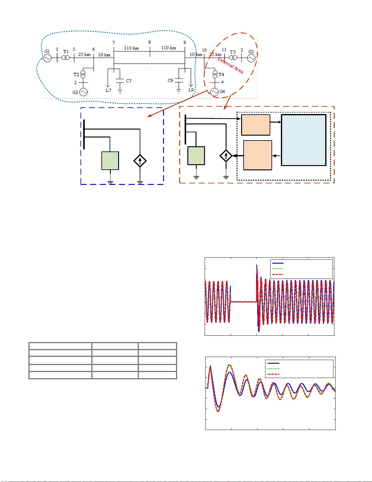
This is the accepte d version Live link to published v ersion in IEEE Xplo re: https://ieeexplore.ieee.org/document/7741877 Citation to the original IEEE publication: A. Thakallapelli, S. Ghosh and S. Kamalasadan, "Real- time frequency based reduced order m odeling of large power grid ," Power and Energy Society General Meeting, 20 16 , Boston, MA, USA. Digital Object Identifier (DOI): 10 .1109 /PESGM.2016.774 1877 The following copyright notice is displayed here as per Operations Manual Section 8.1.9 on Electronic Information Dissemination (known fa m iliarly as "author posting policy"): © 2016 IEEE. Perso nal use of this material is per mitted. Permission from IEEE m ust be o btained for all ot her uses, in an y current or futu re media, includ ing reprinting/republishing this m ater ial f or adv ertising or p romotional pu rposes, creating new collective works, for resale or redistribution to servers or lists, o r reuse of any copyrig hted component of this work in other works. Abstract — Large p ower system s are comp lex and re al-ti me modeling of the grid for electro magnetic simulation (EM T) studies is impractical . In general, there are methods that reduce large power system into an equivalent networ k that requires less computational resource, while preserving electromechanical (l ow frequency) a nd h igh frequency behavio r of the orig inal system. This can be achieved by modeling the area not of interest (external area) as a combination of Transient Sta bility Analysis (TSA) type phasor model equivalent a nd Fre quency Depen dent Network Equivalent (FDNE). TSA retains electromechanical behavior, w hereas FDNE retains high frequency behavior of the original power system. To this effect, this p aper introduces a method of developing FDNE based on an online recursive least squares (RLS) identification algorithm in z-domain, and modelin g of reduced po wer systems as FDNE and as a co mbination of TSA and FDNE using real-time digital simulators. Index Terms — Real-time Simu lator, Electromagnetic Simulation, Transient Stability Type Equivalen t, Freq uency Dependent Netw ork Equivalent (FDNE), Recursive Least Square Identification (RLS). I. I NTRODUCTI ON U sing electro magnetic (EMT) simulation, po wer system can be modeled i n detail to understand the effect of transients du e to switching, reso nance, etc. W ith large penetration of renewable energ y sources like wind and photo voltaic syste m, the effect of power electronic co mponents on the po wer grid can also be studied using EM T simulation. T he integration step size of EMT si mulation is i n micro seconds ( µs ) . On the ot her hand, i n TS A type simulatio n o nly dynamic co mponents like generators, turb ines, and go vernors are model ed in d etail with fast time dynamic s s uch as net work transients are aggregated . The integration time step of TSA models is lar ge, which makes TSA simulatio n faster than EMT simulation e ven thou gh not very accurate. Detailed m ode ling of full scale large po wer system in real - time EMT simulation is i mpractical as this requires larger computational resource. Since modern real -time simulator’s run using parallel co mputing processors, increase network size require m ore number o f processors as well . One way t o red uce computational time and numb er of processors required is to model o nly p art of the net work to be studied ( study area) in which tran sient p henomenon or the effect o f po w er e lectronic A. Thakallapell i, S. Ghosh, and S. Kamalasadan (corresponding author), are with the Pow er, Energy and I ntelligent Sy stems Laboratory , En ergy Production Infrastructure Center (EPIC) and Dep artment of Electri cal Engineering, University of North Carolina at Charlotte, Charlotte, NC 28223 USA (e-mail : athakall@uncc.edu , sghosh9@uncc.ed u , skamalas@unc c.edu ). devices occurs an d the n represent the rest of the n etwor k (external area) as an eq uivalent. The external area is generally modeled as TSA t ype i n which the network is der ived as simple inductances from sh ort circuit impeda nces at the terminal buse s evaluated at power frequency. T his representatio n thus ignores h igh freq uency oscillations. T o consider high freq uency transient p henomenon FDNE must be considered. If external area is m odel ed only as FDNE, the effect of high f req uency tra nsients on generato r dynamics cannot b e observed, which means the electromechanical oscillations are ignored. Thus in order to cover both electromechanic al (low frequency) and high frequency behavior, external area should be modeled as TSA in parallel with FDNE. In previous works, FDNEs are formulated as frequency- dependent black -box ter minal equivalent s based on r ational functions. These models can easil y be i nterfaced with EM TP type si mulation platforms u sing a lumped circuit equivale nt, or by recursive convol ution. More r ecently FDNEs are formulated using an ad mittance representatio n. I nitially sh ort circuited ad mittance o f a network for a wide frequenc y ra nge is co mputed u sing si mulated time do main responses and curve fitting technique s based on weighted polynomials. Also pole relocation (vector fitting) me thods ar e ap plied for fitt ing the rational model to t he i nitially co mputed ad mittance o ver a wide frequency ra nge ([1]-[6]). Calculation of ad mittance using simulated time domain responses over a wide frequency range is tedio us. For e xample, if frequency range o f i nterest is from 0 to 10 00 Hz and step size o f frequency increment i s 0.1 Hz, the total frequency sampl es un der consideration are 10001 samples. For each frequency, sam ple calculation of 1 0001 admittances based on simulated time domain responses is extremely co mplex. This co mplexit y increa ses wit h sa mple size of freq uencies, nu mber of po rts, and size of net work under consideration. In this paper a novel met hod of formulating FDNEs b ased on o nline recursive least square identification is intr oduced. In this method external ar ea is energized with co nstant voltage source after all the voltage sources are s hort circuited, and current sources are op en circ uited. S ubsequently by tr acking input voltage and output cur rent, FDNE is formulated in z - domain. The pro posed method is a d irect way o f finding FDNE which reduces complexity in finding admittance matrix over a wide frequenc y range and decreases co mputational time. T o further reduce co mputational time number of buses ( nodes) in external area for T SA t ype simulation are red uced usi ng Kron ’ s n ode elimin ation method and all generating units in external are aggregated using inertial aggrega tion method. Real-time Frequency Based Reduced Order Modeling of Lar ge Power Grid Abilash Thakallap elli, Student Member, IEEE , S udipta Ghosh, Member, IEEE, Suk umar Kamalasadan , Member, IEEE The rest of the paper is organized as follows: In sectio n II the p roposed algor ithm for TSA and FDNE is discussed. For this, initially Kro n ’s nod e elimination met hod is discus sed, then generators and associa ted contro llers aggregation are discussed, th en RLS identification for FDNE formu lation is discussed. In section III, implementation method of the proposed architecture in OP AL-RT (HYP ERSIM) ® real-time is illustrated. Section IV discusses the results o n a power grid using Kund ur’s two area test system and Section V co ncludes the paper. II. P ROPOSED A LGO RITHM The propo sed algorithm has t wo p arts a) T SA and b) FDNE . The details are discussed below. 1) Aggregation of E xternal area for TSA Initially ag gregated TSA model is formulated for retaining electromechanical behavior of the external system. Aggregation is done in t wo steps: 1) Network aggregatio n, 2) Generator and a ssociated contr oller aggregatio n. a) Network Aggregatio n For net work aggr egation first a dmittance matrix '' Y of the external ar ea is formulated offline using line and bus data. If there is '' n no o f buses in the external area and we want to retain two buses (boundary bus and generator bus) in the external area re maining ' 2 ' n − buses can b e el iminated using '' red Y [7], where 1 2 2 2 2 [] re d x xn nx n nx Y Y Y Y Y − =− and (1) bb red gg IV Y IV = (2) where, subscrip t '' b and '' g stand for the boundar y bus and equivalent generator b us. b) Generator an d Associa ted Controller Aggrega tion Generators and associated controllers for a large system can be aggregated before modeling T SA. Me thod of aggregat ion is discussed in [8 ]. T hus additi onal details are not explained in the paper. 2) Frequency Dep endent Network Equ ivalent Formulation In this m ethod external area is energized with constant voltage source after short circuiting all voltage source s, and open circuiti ng all c urrent sources. By tracki ng input voltage and output current, FDNE is the n formulated in z -domain using R LS. Basic pr inciple is as follows. If '' b V is the voltage input to the boundary b us an d '' b I is the curr ent o utput from the b oundary b us, then frequency dependent ad mittance can be written as () () () b b Ik Yz Vk = (3) where, k is the sampling inter val or sampling time . a) Recursive Least Sq uare Id entification Identification of a dynamic process is per formed ever y sample period using the process i nput ' ( ) ' uk and the p rocess output ' ( ) ' yk at ever y sa mple '' k . Considering the z -do main model of an n th order p rocess, this can be rep resented as 12 12 12 12 ..... () () 1 ..... n n n n b z b z b z yk uk a z a z a z − − − − − − + + + = + + + + (4) For '' N observation window lengt h, (4) can be rewritten as 1 2 1 ( 1) ( 2 1) . () . ( 1 ) . . . . . ( 1 ) n Nx n Nx n nx a yk yk a X b y k N b − = −+ (5) Equation (5) can be written in the generic form as m od ( 1) ( 2 ) ( 2 1) el N x Nx n nx X = (6) Assume that the model id entified is d ifferent fro m measurements, then mod mea sured el = − (7) Where , '' is the err or bet ween the per formance of the system and model, for which criteria '' J can defined as t J = (8) By letting 0, d J d = we get 1 [] tt m ea sur ed X X X − = (9) From (9) it can be seen in order to get the measured variable, the i nverse of the state matrix should b e deter mined. This ca n drastically slo w do wn the p rocess and some time may even not achie vable. To circumvent this issues, a recursive least squares technique is used. R LS is a computational algorithm t hat eli minates the matrix inversion. Let , t S X X = then (9) can be written as 1 t SX − = where = measured (10) 1 () ( ) [ ( ) ( 1 )] ( 1 ) t k k S x k X k k − = − − (11) 1 ( ) [ ( ) ( ) ( 1 ) ( 1 )] t k S x k k X k k − = + − − (12) using (6) 1 ( ) [ ( ) ( ) ( 1 ) ( 1 ) ( 1 ) ] t k S x k k X k X k k − = + − − − (13) 1 ( ) [ ( ) ( ) ( 1 ) ( 1 )] k S x k k S k k − = + − − (14) since, ( ) ( - 1 ) ( ) ' ( ) S k S k x k x k =+ (15) Substituting (15 ) in (14) 1 ( ) [ ( ) ( ) ( ) ( ) ' ( ) ( 1 ) ] k S x k k S k x k x k k − = + − − (16) 1 ( ) ( 1 ) [ ( 1 ) ( ) ' ( )] ( ) [ ( ) ' ( ) ( 1 ) ] k k S k x k x k x k k x k k − = − + − + − − (17) Let 1 ( ) ( ), P k S k − = and b y matrix inversion lem ma P ( k) can be represented as ( ) ' ( ) ( 1 ) ( ) ( 1 )[ ] 1 ' ( ) ( 1 ) ( ) x k x k P k P k P k I x k P k x k − = − − +− (18) Substituting (18 ) in (17) and letting ( 1 ) ( ) () 1 ' ( ) ( 1 ) ( ) P k x k Kk x k P k x k − = +− (19) Where P (k) can be written as ( ) [ ( ) ' ( ) ] ( 1 ) P k I K k x k P k = − − (20) Therefore, (17) can be represented as ( ) ( 1 ) ( )[ ( ) ' ( ) ( 1 )] k k K k k x k k = − + − − (21) With weighted least square , (19 ) and (20) can be presented as ( 1 ) ( ) () ' ( ) ( 1 ) ( ) P k x k Kk x k P k x k − = +− (22) [ ( ) ' ( ) ] ( 1 ) () I K k x k P k Pk −− = (23) where '' is the weighting facto r. This with a given process input ' ( ) ' b Vk and process output ' ( ) ' b Ik , Y (z) can be computed using RLS id entification [9 ]. III. I MPLEMENTATIO N OF TSA AND FDNE IN HYP ERSIM REAL - TI ME DIGITAL S IMULA T OR Implementation method of the propo sed algorithm in real- time digital simulato r is a two-step proce ss: 1) I nterfacing T SA type modeling w ith real-ti me simulator, and 2) Interfacin g FDNE with real -time s imula tor. T he o verall f lowchart is as shown in Fig. 1. Powe r System Mo del Exter nal Area FDNE TSA Com pute Y(z ) us ing RLS (Eqn s . 4- 23 ) Com pute Aggre gated TSA Mode l and boun dary b us cur rent (Eqn s . 24 - 25 ) IF =Y(z )* V b (Eqn . 27 ) I inj =I+Y f *V b (Eqn . 26 ) if F DNE is N O Y f =0 els e Y f =Y( 60 Hz ) Cohe rency groupi ng Stu dy Area Bo u ndar y Bus Volta ge and cur rent(V b ,I inj ) Bo u ndar y Bus Curr ent Inje ct ion (I inj ) Yes Equiva lent Current Inject i on at Bo u ndar y Bu s(for FDN E Based M odel) (Eqn . 28 ) No Fig 1. I mplementation of FD NE and TSA. 1) Interfacing TSA type model ing with real-time simulator In this step , i nput to the T SA b lock is considered the voltage at the boundary bus, and output from the TSA block is current that is to be injected into the boundary bu s. Here, first, the generator bus voltage is calc ulated as sho wn in (24 ). In this case, ge nerator is modele d in detail to obser ve the electromechanical b ehavior. Conversion of bo undary b us voltage from ti me do main to phasor domain is then performed using discrete measurement posit ive sequence funda mental component of the volta ge. This gives magnitude b V and phase angle b V . Also phase angle of '' b V with reference to '' b I is bb IV − . From this, 1 () g g bb b gg V I Y V Y − =− (24) where, g I is the generator current i njection and b V boundary bus voltage. Generator volta ge g V is calculated recursively every time step. Fro m calculated g V and boundar y bus voltage b V , bo undary b us current inj ection bin j I is calculated as sho wn in (25)-(26 ). b bb b bg g I Y V Y V =+ (25) (6 0 ) bi nj b b I I Y H z V =+ (26) where, (60 ) Y Hz is the funda mental frequency co mponent o f () Yz as indicated in (3 ). T hen (60 ) b Y H z V term is add ed before injecting boundary b us current to remove fundamental frequency component from FDNE . After calculating boundary bus current in phasor form, the current is converted into instantaneous value a nd injected into the boundary bus. The overall representation is as sho wn in Fig. 2. 2) Interfacing FDNE with real time simulator FDNE can be direc tly implemented since it is co mputed in z-domain. With process input as b V and pro cess output as b I , and with third order identification, (4) can be written as 1 2 3 1 2 3 ( ) ( 1 ) ( 2 ) ( 3 ) ( 1 ) ( 2) ( 3 ) F F F F b b b I k a I k a I k a I k b V k b V k b V k = − − − − − − + − + − + − (27) where F I is current output o f FDNE. If only FDNE part is used t hen the T SA part in Fig. 1 is ignored and bou ndary current is ca lculated fro m load flo w results to maintain b oundary bus par ameters at initial ste ady state [14]. * bb bb P jQ I V + = (28) where, b P and b Q are the active and r eactive power flow fro m the bo undary bus, b V and b are the voltage and angle of the boundary bus. IV. I M PL EMENTATION T EST ON I N TERCONNECTED P OW ER G RID For illustration purpo se Kundur’s t wo -area test system is considered (Fig. 2 ). The system consists of t wo areas containing four 900MVA synchronous generato rs each connected by weak tie line s. To assess the perfor mance of o ur proposed FDNE-TS A based model, at first grouping o f generators is done based on slow coherency method ([10] - [13]). Based on this, then the test syste m is divided into study and external area. In this example, area-1 which includes Gen 1 & Gen 2 is considered as ‘study area’ a nd Area -2 wh ich incl udes Ge n 3 & Gen4 as ‘external area ’. Generator s in external area are aggregated usi ng inertial ag gregation met hod and ne t work is reduced based on Kron’s reduction. T hen the prop osed equivalent T SA b ased model is d eveloped . Finally FDNE is formulated usin g RLS identificatio n procedure. T wo cases are studied to evaluate the performance of the arc hitecture. In the first case both FDNE+T SA based model is interfaced with study area at bo undary bus (b us 10). In the second case TSA part is ignored and onl y FDNE is interfaced with the study area at boundar y bus, and boundary bu s is e nergized with const ant current source calculated as sho wn in (2 8) . T o co mpare the performance of the d ifferent m odel s a three phase short circuit fault at bus 8 was initiated at 0.1 sec and cleared at 0.2 sec (Fig. 2 ). T able I shows the total time req uired to compile a nd run real-time simulation for 5sec. Previous stu dies have indicated, for large power grid significant difference in simulation time and accurac y can be observed [15]. TABLE I C OMPARISON OF D IFFERENT M ODELS Model Accuracy Speed Full Mode l Excellent 8.88 sec FDNE+TSA Based Model Very G ood 7.61 sec FDNE Base d Model Good 7.5 sec TSA Based Mo del Poor 7.55 sec Fig. 3 show s voltage at the fault bus. Fig. 4 s hows t he relative speed o f Generator 2 w ith res pect to Generator 1 (Swing). Fig. 5 and Fig. 6 show active p ower generation of Generator 1 and Generator 2 respectively. Fig. 7 shows active po wer flow from bus 9- 7. As it can b e observe d, the s ystem respo nse i s over all comparable and close to the full model representat ion with reduction in the co mputational speed . Fig . 8 shows the po wer flow from the boundar y bus (bus 10 - 9) , where TSA+FDNE based and TSA based model (FDNE is ignored and o nly T SA part is interfaced with bo undary bus) is compared with t he full model . Fro m Fi g. 8 it is clear that TS A based model shows i naccuracy which can be further improved by add ing FDNE . Fig. 9 shows the per centage error of active power flo w from bu s 10 - 9 with respec t to the full model. Based on this test, T able I sho ws qualitative representatio n o f the acc uracy co mparisons . Fro m the ab ove re sults it can be concluded that FDNE+TS A based eq uivalent model ha s cl ose agreement in their behavior with the full model i n all aspect. 0 0.1 0.2 0.3 0.4 0.5 -3 0 0 -2 0 0 -1 0 0 0 100 200 300 400 time (s) Voltage (kV) Fu ll M o de l FDNE+ TSA B a s e d M o de l FDNE B a s e d M ode l Fig. 3. The vol tage at bus 8 (fault b us). 0 1 2 3 4 5 -0 .4 -0 .3 -0 .2 -0 .1 0 0.1 0.2 0.3 time (s) Relative Speed (rad/sec) Ful l M o de l FDNE+ TSA B as e d M o de l FDNE B a s e d M o de l Fig. 4. Relative Speed of G 2 with respect to G 1 (swing). Fig. 2. Proposed dyn amic equivalen t of Kundur two area test system. GND4 TSA AGGREGATED MODEL FDNE Y(z) GND5 PHASOR DOM AIN Bound ary B us Voltage (EMT to Pha sor Conv ersion) Bound ary B us Curr ent Injection (Phasor to EMT Conv ersion) 10 Study A rea GND4 FDNE Y(z) GND5 Constan t Curr ent Sour ce 10 TSA+F DNE B ased Equiva lent FDNE B ased Equiva lent 0 0.1 0.2 0.3 0 .4 0 .5 200 300 400 500 600 700 800 900 time (s) Active Power (MW) Ful l M o de l FDNE+TSA B as e d Mo de l FDNE B a s e d M o de l Fig. 5. The output active powe r of Gen 1. 0 0.1 0.2 0 .3 0 .4 0.5 0 200 400 600 800 1000 time (s) Active Power (MW) Ful l M o de l FDNE+TSA B as e d M o de l FDNE B a s e d M o de l Fig. 6. The output active power of Gen 2. 0 0.1 0.2 0 .3 0.4 0.5 -8 00 -6 00 -4 00 -2 00 0 time (s) Active Power (MW) Ful l Model FDNE+T SA Base d M o del FDNE Based Model Fig. 7. The line fl ow from bus 9- 7. 0 0.1 0.2 0.3 0.4 0.5 200 400 600 800 1000 1200 1400 1600 1800 time (s) Active Power (MW) Ful l Model FDNE+T SA Base d Model T SA Base d Model Fig. 8 . Pow er Flow fro m boundary bus 10 - 9. 0 0. 1 0 . 2 0 . 3 0 . 4 0 .5 -80 -60 -40 -20 0 20 time (s) Percentage Error FDNE B a s e d M ode l TSA+FDNE M o de l TSA B as e d M o de l Fig. 9. Percentag e error in powe r from bus 10-9, compared to full model. V. C ONCLUSION The proposed frequenc y based reduced order modeling of large po wer grid in the real-time simulator is si mple approach which models the “study” area using a detailed EMT solution and the “external” area as eq uivalent. Equivalenc y is modeled as FDNE usi ng RLS which represent the high -frequenc y behavior, and coherenc y based TSA to represent electromechanical behavior. The pro posed meth od is validated on Kundur t wo area 4 machine sys tems. T he red uced o rder model (based on FDNE+T SA) s hows close a gree ment w ith full model. T he advantage is that the r educed representation can r eplace the origi nal model for further d ynamic asses sment. This p roof of concept illustra tes that large po wer s ystems can be modeled as eq uivalents in real-time simulators by reduci ng nu mber of buses, and b y aggregating generators and associated controllers, while retai ning lo w frequency a nd hi gh freque ncy behavior of the original s ystem. VI. R EFERENCES [1] H. Singh and A. Abur, “ Multi-port equivalencing of external systems for simulation of switching transients, ” IEEE Trans. Power Delivery , vol. 10 , no. 1, pp. 374-382, Jan. 19 95. [2] A . Abur and H. Singh, “ Time domain modeling of exte rnal systems for electromagnetic transients programs, ” IEEE Trans. Power Syst , vol. 8 , no. 2, pp. 671-679, M ay 1993. [3] B. Gustavsen and O. Mo, “ Interfacing convolution based linear models to an electromag netic transients progr am, ” in Proc. Int. Con f. Power Systems Transien ts , Lyon, Fr ance, Jun. 4-7, 2007, pp. 4-7. [4] B. Gustavsen a nd A. Se mlyen, “ Rational approximation of frequency domain responses by vector fitting, ” IEEE Trans. Power Del , vol. 14, no. 3, pp. 1052-1061, J ul. 1999. [5] A . Semlyen and M. R. I ravani , “ Frequency domain modeling of ex ternal systems in an electro-magnetic trans ients program, ” IEEE Trans. Power Syst. , vol. 8, no. 2, pp. 527 -533, May 199 3. [6] Y. Zha ng et al . , “ Devel opment and analysis of applicab ility of a hybrid transient simulation platform combining TSA and EMT eleme nts, ” IEEE Trans. Power Sys t. , vol. 28, no. 1, pp. 357- 366 , Feb. 201 3. [7] Pow er System Analysis. Available : http://nptel.ac.in/course s/Webcourse- contents/II T-Kanpur/power- system/chapter_3/3_6.html. [8] J. C how, P. A ccari, and W. Pric e, “ Inertial and slo w coherency aggreg ation algo rithms for po wer system dy namic model reduction, ” IEEE Trans. Power S yst., vol. 10, no. 2, pp. 680-685, May 1995. [9] K . J. Å ström and B. W ittenmark, Adaptive control . Reading, MA: Addison-We sley Publishing Compan y, 1995. [10] J. H. Chow , Power system coherency and model reduction . New York, NY, USA: S pringer, 2013. [11] S. Ghosh and N. Senroy, “ The localness of ele ctromechanica l oscillations in power systems, ” Int. J. Elect. Power Energy . Syst., vol. 42, no. 1, pp. 306-313, Nov. 2012. [12] S. Ghosh, S. Kamalasadan, N. Senroy and J. Enslin, “Doubly Fed Induction Ge nerator (DFIG)-based Wind Farm Control Framework for Primary Frequency and Inertial Response Application”, IEEE Trans. Power Syst. , no. 99, pp. 1-11, Jun. 20 15. [13] S . Kamalasada n a nd A. Hande, “A PID Controller for Real -Time DC Motor Speed Co ntrol u sing the C505C Microcontr oller ”, CAI NE, pp. 1 - 8, 2004. [14] X. Lin, “ Sy stem Equivalent for Real Time D igital Simulator ” , Ph.D dissertation, Dept Elect Eng., Univ. of M anitoba, Winnipeg , Manitoba , Jan. 2011. [Online ]. Available: http://hdl.handle.net/19 93/4375. [15] A. Ubolli and B. G u stavsen, “Multi port frequency -dependent n etwo rk equivalencing based on simulated time- domain responses, ” IEEE Trans. Power Del., vol . 27, no. 2, pp. 648-65 7, Apr. 2012.
Original Paper
Loading high-quality paper...
Comments & Academic Discussion
Loading comments...
Leave a Comment