Converting a Common Document Scanner to a Multispectral Scanner
We propose the construction of a prototype scanner designed to capture multispectral images of documents. A standard sheet-feed scanner is modified by disconnecting its internal light source and connecting an external multispectral light source compr…
Authors: Zohaib Khan, Faisal Shafait, Ajmal Mian
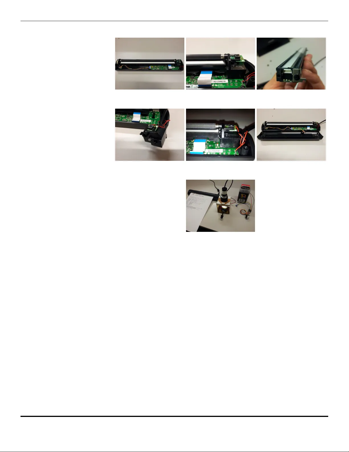
Con v erting a Common Do cumen t Scanner to a Multisp ectral Scanner Zohaib Khan 1,2 , F aisal Shafait 1,3 , Ajmal Mian 1,* 1 Departmen t of Computer Science and Softw are Engineering, The Univ ersit y of W estern Australia, Cra wley , W A, Australia 2 Sc ho ol of Information T ec hnology and Mathematical Sciences, Univ ersit y of South Australia, Adelaide, SA, Australia 3 Sc ho ol of Electrical Engineering and Computer Science (SEECS), National Univ ersity of Science and T echnology (NUST), Islamabad, P akistan * a jmal.mian@uw a.edu.au Abstract W e prop ose the construction of a protot yp e scanner designed to capture m ultisp ectral images of do cumen ts. A standard sheet-feed scanner is mo dified b y disconnecting its in ternal light source and connecting an external m ultispectral light source comprising of narro w band light emitting diodes (LED). A do cumen t is scanned by illuminating the scanner ligh t guide successively with differen t LEDs and capturing a scan of the do cumen t. The system is p ortable and can be used for p otential applications in v erification of questioned do cumen ts, cheques, receipts and bank notes. 1 In tro duction F orensic analysis of questioned do cuments in v olves a broad range of activities [10]. This includes establishing, whether a do cumen t originated from a particular source, bac kdated, forged or willfully manipulated. Disputes ov er the authen ticity of bank c heques, purchase receipts, currency notes [1] or seals in agreemen ts [9] can in volv e o verwhelmingly complex legal procedures in resolution. In other cases, verification of gen uineness of do cumen t source (written or printed) is also of significan t in terest to fraud detection [11]. The estimated age of a testament (will) can sometimes pla y a crucial role in the resolution of inheritance. T raditionally , forensic scien tists mak e empirical or experimental observ ations ab out a suspicious p ortion of the do cumen t in a forensic lab oratory . The observ ations are then coupled with exp ert opinions to b e presentable in a court-of-la w. As this pro cess largely relies on individual exp ertise and analysis, its consequences may b e critical to the rights of a p erson, business or an organization. There is an interest in mechanisms for pre-examination of questioned do cumen ts b efore legally pursuing and b earing substan tial costs in a court-of-law. Computerized forensic analysis has recently pav ed w ay for automatic do cumen t forgery detection using multisp e ctr al imaging [4, 5]. Multisp ectral or hypersp ectral do cumen t scanners are generally comprised of bulky apparatus and require sp ecialized lab oratory environmen t for op eration. This op ens the need for the dev elopment of a p ortable multispectral do cument scanning system. 1/9 There are different wa ys of capturing multispectral images of a scene, eac h suits to a target application [12]. A sp atial sc anner simultaneously captures ( x, λ ) dimensions of a scene, whereas the y dimension is captured by mov emen t of the sensor or the scene. It is suitable for scenarios where either the scene or the sensing platform is moving such as in remote sensing. A sp e ctr al sc anner simultaneously captures ( x, y ) dimensions of a scene, whereas the λ dimension is captured b y sp ectral tuning [2]. It is sp ecifically useful in a setup where b oth the scene and the sensing platform are stationary . In con trast, a snapshot sp atio-sp e ctr al sensor simultaneously captures ( x, y , λ ) dimensions of a scene without the need for scanning. This metho d can effectively b e used in conditions where the scene and the sensing platform are simultaneously mo ving. Ho wev er, its complex sensor design incurs heavy costs limiting its use in applications lik e in-vivo imaging of organisms [3]. Previously , w e prop osed a sp ectral scanning system for capturing multispectral images of a do cumen t [7, 8]. Despite the simplicit y of a static scene and sensor, the system w as prone to artifacts of camera captured imaging (illumination, p ersp ectiv e etc.) [6]. In this w ork, we prop ose a sp atio-sp e ctr al sc anner for capturing multispectral image of a do cument using a sheet-feed scanner, thus av oiding problems asso ciated with camera capture. It captures one spatial dimension x whereas the ( y , λ ) dimensions are sequen tially captured by feeding the do cumen t and tuning illumination sp ectrum, resp ectiv ely . In the following section, we describ e the prop osed multispectral do cument scanning system, in terms of its electrical, sp ectral, optical and thermal design. 2 Multisp ectral Scanner Design The main comp onen ts of the proposed multispectral do cumen t scanner are a standard do cumen t scanner and an external m ultispectral light source. Figure 1. Do cumen t scan- ner The DSmobile600 sheet-feed p ortable do cumen t scanner from Br other Mobile Solutions Inc. . Connection of an external source of ligh t can b e intrusiv e to the mov ement of the scanner carriage unit in a flatb ed scanner which may cause discrepancies in the scanned image. In con trast, a sheet-feed scanner allows in tegration with an external source of light without b eing in trusive to the scanner op eration. Since the scanning unit of a sheet-feed scanner is stationary , its op eration is not affected by connection to an external source of light. A sheet-feed mec hanism is therefore preferred ov er a flatb ed construction to form the basis of a m ultispectral do cument scanner. The size of a sheet-feed scanner is mainly determined b y the shorter edge of the supp orted page size whic h makes it compact and p ortable as shown in Figure 1. A broadband source of ligh t (e.g., incandescent or fluorescent) reflects the av erage resp onse of a scene ov er a wide sp ectral range, and therefore achiev es low sp ectral fidelit y . A multispectral source pro duces ligh t in narrow sp ectral bands, attaining high sp ectral fidelity . Light Emitting Diodes (LEDs) can provide such selectivity required in the sp ectral profile of a multispectral light source. Another fav orable characteristic of LEDs is that they are highly efficien t compared to other sources of light. 2.1 Electrical Sc hematic The electrical schematic of the multispectral light source is given in Figure 2. It consists of a constan t current source (i1) connected to narrow-band LEDs (d1-d7) via switch (s1-s7). The constan t current source limits the current from surpassing the absolute maxim um current rating of the LED. It also makes an LED glow with the same 2/9 luminous p o w er and sp ectral profile, making the system reliab le. How ev er, an inadv ertent connection of multiple switches simultaneously can result in current b eing divided in sev eral LEDs. Figure 2. Sc hematic diagram of the multispectral light source. Connection lay out of the LEDs (d1-d7) and the constan t current source (i1) via switches (s1-s7). Figure 3. Rotary switch. A 30 degree indexing, 12 wa y unip o- lar switc h PT-6015 from L orlin Ele ctr onics and its diagram of ter- minal connections. In order to ensure only one LED is p o w ered at a time, a unip olar multi-w a y rotary switch is included in the design. It pro vides non-shorting, break-b efore-mak e contacts, to av oid ov erloading of the source with m ultiple LEDs during switching. It can handle high curren ts of 500mA @ 250V ac/dc whic h is within the op erating limits of the constan t current source (350mA). The switch and its terminal p ositions as viewed from the knob end of the spindle are sho wn in Figure 3. T erminal A (middle) is connected to the p ositiv e end of the constant current source. T erminals 1-7 are connected to p ositive terminal of d1-d7, resp ectiv ely . T erminals 8-12 are not utilized. Tw o different constant current sources were designed dep ending on av ailability of a lo w or high input voltage source. The electrical schematic of the sources and their assem bled form are shown in Figure 4. 2.1.1 Lo w Input V oltage - Constan t Curren t Source The lo w input voltage constant current source uses a MicroPuck LED Po w er Mo dule whic h can provide a constant (350mA) current to a single LED. The miniature design allo ws flexibility to use one or t w o AA sized batteries to p o wer the mo dule. It provides maxim um current to the LEDs while mimicking the light drop-off of an incandescent bulb, whic h dims as the batteries drain. How ev er, the current drops only at very low v oltages, allowing maximum op erational time. The driver has tw o input pins (V in+ , V in- ) and t wo output pins (V out+ , V out- ). 2.1.2 High Input V oltage - Constan t Curren t Source The high input v oltage constant current source uses a BuckPuc k LED Po w er Mo dule whic h can pro vide a constant (350mA) current to multiple LEDs, although the prop osed switc h ensures only one LED is p o wered at a time. The mo dule provides manual dimming con trol through a p oten tiometer which uses internal reference from the Buc kPuck driver. It also has built-in op en-circuit and short-circuit protection. The mo dule has four input pins (V in+ , V in- , Ref, Ctrl) and t wo output pins (V out+ , V out- ). 2.2 Sp ectral Profile The c hoice of colored LEDs is imp ortan t for description of the sp ectral profile of the m ultisp ectral light source. The sp ectral characteristics of LEDs are characterized b y tw o 3/9 (a) MicroPuck driver (ic1) pow ered by a lo w input voltage source (v1). (b) Assembled lo w input v oltage - constant cur- rent source (c) BuckPuc k driv er(ic2) p ow ered b y a high input voltage source (v2). (d) Asssembled high input voltage - constant current source Figure 4. Constan t current sources (a) Schematic of the low input voltage source. The input terminals (V in+ ,V in- ) are connected to a low voltage source (v1=0.8-3 Vdc) and the output terminals (V out+ ,V out- ) are connected to LED. (b) Schematic of the high input v oltage source. The input terminals (V in+ ,V in- ) are connected to a high voltage source (v1=7-32 Vdc) and the output terminals (V out+ ,V out- ) are connected to LED. The p oten tiometer (r1) allows dimming control (Ctrl) via internal reference (Ref). main parameters, i.e. the cen ter wa v elength and the sp ectral bandwidth. The relative sp ectral p o wer distribution of the LEDs is given in Figure 5(b). These LEDs almost co ver the range of visible electromagnetic sp ectrum (400nm-700nm) at approximately regular in terv als. The sp ectral parameters of the LEDs are provided in T able 1. Note that the LEDs are spread across the sp ectrum with sufficiently narrow-bands and high luminous p o wer whic h makes an effective multispectral light source. T able 1. Sp ecifications of Luxeon Reb el LED series used in multispectral light source. Color W av elength Bandwidth Luminous Flux Part Number (nm) (nm) (lm,mW) model Deep Red 655 20 640 LXM3-PD01 Red-Orange 617 20 90 LXML-PH01-0050 Amber 590 20 77 LXML-PL01-0040 Green 530 30 150 LXML-PM01-0090 Cyan 505 30 122 LXML-PE01-0070 Roy al Blue 447.5 20 1030 LXML-PR02-A900 2.3 Optical Configuration The purp ose of optical assembly is to transmit multispectral light into the to scanner ligh t guide. The concentrator optics are suitable for b eam insertion into fib er optic bundles or ligh t guides. Two different optical arrangements were prop osed for m ultisp ectral light source shown in Figure 6. 4/9 Figure 5. (a) A few Philips Luxe on R eb el LEDs in differen t colors. (b) Relative Sp ectral P ow er Distribution of the LEDs 2.3.1 Linear LEDs with concen trator lens In this arrangemen t, an LED is pre-soldered to a base with ano de(+) and catho de(-) connections at lo cations as shown in Figure 6(a). Multiple such units, each with a differen t color LED together make a multispectral light source. A fib er b eam lens ( Car clo Inc. ) fo cuses ligh t from LED into an 8 degree narrow b eam at a fo cal distance of 11mm. The diameter of the lens is 20mm and conforms to the LED base. It requires a circular lens holder sho wn in Figure 6(c) which is affixed to the base using a double-sided tap e. The holder p ositions the lens at appropriate distance from the LED for maxim um luminous transmission. The fo cused b eam is then fed to a flexible light guide. 2.3.2 Arra y LED base with cluster concentrator optic In this arrangemen t, an array of LEDs is pre-soldered to a single base with separate ano de(+) and catho de(-) connections for eac h unit at lo cations as shown in Figure 6(b). A cluster concentrator optic ( Polymer Optics Ltd. ) fo cuses ligh t from sev en LEDs in to a 12mm narro w b eam at a focal distance of 25mm. It uses an optical grade p oly-carbonate material for thermal stability and system durability which results in high ligh t collection efficiency (85%). The use of array LEDs and cluster optic makes the ligh t source compact and rigid. (a) Single LED assembly (b) 7-LED round assembly (c) Fib er coupler concentrator lens and round optic holder (d) Multi-cell cluster concentrator optic with p egged feet Figure 6. Differen t comp onents in the tw o optical configurations of m ultispectral ligh t source. 5/9 The t wo optical configurations after assembly are shown in Figure 7. (a) Single LED assembly with sol- dered connections (b) Carclo lens in round lens holder (c) Patched up comp onents of linear optical configuration (d) Array LED assembly with sol- dered connections (e) Array LED assembly with clus- ter concentrator lens (f) Patc hed up comp onents of array optical configuration Figure 7. Steps for assembly of different optical configurations, linear (top row) and arra y (b ottom row) 2.4 Thermal Consideration Figure 8. Heat sink A 3D view of heat sink CN40-15B from AL- PHA Co. Ltd . The use of high-p o w er LEDs introduces considerable thermal efficiency issues whic h can ov erheat the LEDs if not catered for correctly . A heat sink is an affordable device for maintaining near constan t temp erature of LEDs for long p eriods of op eration. W e used a natural con vection heat sink, which is a 40mm round base with 15mm high legs as sho wn in Figure 8. It has the highest thermal efficiency (degree Celsius p er W att) in the CN40 series of heat sinks. 2.5 Scanner Mo dification Mo dification of the sheet-feed scanner consists of the following steps: 1. Gaining access to the internal micro illumination source (RGB LED) of the scanner. 2. Remo ving/Disabling of the internal RGB LED. 3. Structural mo dification of scanner housing for placement of flexible light guide. 4. Connection of external light source to the internal light guide via flexible light guide. The pro cedure is illustrated in detail in Figure 9 6/9 (a) Gain access by removing top cov er (b) Release components from hinge supp ort (c) Disengage R GB LED from scanner sensor (d) Make provision for flexible light guide (e) Reinstall comp onents (f) Replace top cov er (g) Connection to m ultisp ectral light source Figure 9. Steps of scanner mo dification and assembly of multispectral light source. 3 Multisp ectral Do cumen t Scanning In order to test the m ultisp ectral do cumen t scanner, a test page w as printed from an HP Laserjet Color printer. The RGB true color and v arious bands of a logo in the test page captured b y the multispectral scanner are shown in Figure 10. The logo has red, orange, green and blue elemen ts and the text at the b ottom. Notice that the colored p ortions of the logo hav e a characteristic resp onse to the multispectral light. This demonstrates the abilit y of the scanner to capture fine detail in sp ectral bands. The recen t av ailability of high-resolution printers, has not only supp orted useful purp oses, but also op ened w ays for illegal use in forgery of do cumen ts. This has consequen tly p ersuaded printer manufacturers to hide an invisible coun terfeit protection co de which holds information for printer identification. This unique co de is prin ted in ev ery do cumen t, in the form of rep eated pattern of yello w dots. The unique pattern can in turn b e used to identify the source of a do cumen t. The multispectral do cumen t scanner successfully captures this unique dot-pattern. The unique patterns of differen t printers can b e identified in terms of geometrical relationships. Tw o imp ortan t parameters that form these relationships are the Horizon tal Pattern Separation (HPS) distance and the V ertical Pattern Separation (VPS) distance. A raw image of the Ro y al Blue band of the scanned test page is shown 7/9 Windows Printer Test Page Congratulations! If you can read this information, you have correctly installed your Adobe PDF Converter on ECM-DTC-250. The information below describes your printer driver and port settings. Submitted Time: 4:55:58 AM 29/10/2014 Computer name: ECM-DTC-250 Printer name: Adobe PDF Printer model: Adobe PDF Converter Color support: Yes Port name(s): Documents\*.pdf Data format: RAW Share name: Location: Comment: Driver name: PSCRIPT5.DLL Data file: ADPDF9.PPD Config file: PS5UI.DLL Help file: PSCRIPT.HLP Driver version: 6.00 Environment: Windows x64 Additional files used by this driver: C:\windows\system32\spool\DRIVERS\x64\3\ADUIGP.DLL (11.0.0.305) C:\windows\system32\spool\DRIVERS\x64\3\ADREGP.DLL (11.0.0.305) C:\windows\system32\spool\DRIVERS\x64\3\PSCRPTFE.NTF C:\windows\system32\spool\DRIVERS\x64\3\ADGELP.INI C:\windows\system32\spool\DRIVERS\x64\3\AdobePdf.dll (11.0.0.305) C:\windows\system32\spool\DRIVERS\x64\3\AdobePDFUI.dll (11.0.0.305) C:\windows\system32\spool\DRIVERS\x64\3\PSCRIPT.NTF C:\windows\system32\spool\DRIVERS\x64\3\PS_SCHM.GDL This is the end of the printer test page. W i ndows Printer T e st Page Congratulations! If you can read this information, you have correctly installed your Adobe PDF Converter on ECM-DTC-250. The information below describes your printer driver and port settings. Submitted Time: 4:55:58 AM 29/10/2014 Computer name: ECM-DTC-250 Printer name: Adobe PDF Printer model: Adobe PDF Converter Color support: Yes Port name(s): Documents\*.pdf Data format: RAW Share name: Location: Comment: Driver name: PSCRIPT5.DLL Data file: ADPDF9.PPD Config file: PS5UI.DLL Help file: PSCRIPT.HLP Driver version: 6.00 Environment: Windows x64 Additional files used by this driver: C:\windows\system32\spool\DRIVERS\x64\3\ADUIGP.DLL (11.0.0.305) C:\windows\system32\spool\DRIVERS\x64\3\ADREGP.DLL (11.0.0.305) C:\windows\system32\spool\DRIVERS\x64\3\PSCRPTFE.NTF C:\windows\system32\spool\DRIVERS\x64\3\ADGELP.INI C:\windows\system32\spool\DRIVERS\x64\3\AdobePdf.dll (11.0.0.305) C:\windows\system32\spool\DRIVERS\x64\3\AdobePDFUI.dll (11.0.0.305) C:\windows\system32\spool\DRIVERS\x64\3\PSCRIPT.NTF C:\windows\system32\spool\DRIVERS\x64\3\PS_SCHM.GDL This is the end of the printer test page. Cyan Green Amber RedOrange DeepRed RoyalBlue Figure 10. Multisp ectral image of a logo from printer test do cumen t. Note how the in tensity of p ortions of the logo changes according to sp ectral bands. in Figure 11. (a) Roy al Blue band (b) Pro cessed image Figure 11. The Roy al blue band of a test printer do cumen t (zo om to 6400% to clearly view the pattern). Counterfeit protection pattern extracted by pro cessing of the Roy al Blue band. The co ded patterns are separated by HPS and VPS. 4 Conclusion W e presen ted the design of a prototype multispectral do cumen t scanner which is demonstarted to capture subtle features in a do cument using multispectral light source. The m ultisp ectral light source was designed to cov er the full range of visible electromagnetic sp ectrum and connected to a p ortable sheet-feed do cumen t scanner. The protot yp e design has p otential to b e transformed into a fully functional device suitable for p ortable do cumen t analysis. Ac kno wledgmen ts This researc h work was partially funded by the ARC Grant DP110102399 and the UW A Gran t 00609 10300067. 8/9 References [1] S. Baek, E. Choi, Y. Baek, and C. Lee. Detection of counterfeit banknotes using m ultisp ectral images. Digital Signal Pr o c essing , 78:294–304, 2018. [2] N. Gat. Imaging sp ectroscopy using tunable filters: a review. In Wavelet Applic ations VII , volume 4056, pages 50–65. International So ciet y for Optics and Photonics, 2000. [3] H. C. Hendargo, Y. Zhao, T. Allenb y , and G. M. Palmer. Snap-shot multispectral imaging of v ascular dynamics in a mouse window-c ham b er mo del. Optics letters , 40(14):3292–3295, 2015. [4] M. J. Khan, A. Y ousaf, A. Abbas, and K. Khurshid. Deep learning for automated forgery detection in hypersp ectral do cument images. Journal of Ele ctr onic Imaging , 27(5):053001, 2018. [5] M. J. Khan, A. Y ousaf, K. Khurshid, A. Abbas, and F. Shafait. Automated forgery detection in m ultisp ectral do cument images using fuzzy clustering. In 2018 13th IAPR International Workshop on Do cument Analysis Systems (D AS) , pages 393–398. IEEE, 2018. [6] Z. Khan, F. Shafait, and A. Mian. Hyp ersp ectral do cument imaging: challenges and p erspectives. In International Workshop on Camer a-Base d Do cument Analysis and R e c o gnition , pages 150–163. Springer, 2013. [7] Z. Khan, F. Shafait, and A. Mian. Hyp ersp ectral imaging for ink mismatch detection. In 2013 12th International Confer enc e on Do cument Analysis and R e c o gnition , pages 877–881. IEEE, 2013. [8] Z. Khan, F. Shafait, and A. Mian. Automatic ink mismatch detection for forensic do cumen t analysis. Pattern R e c o gnition , 48(11):3615–3626, 2015. [9] J. Lee, S. G. Kong, Y.-S. Lee, K.-W. Moon, O.-Y. Jeon, J. H. Han, B.-W. Lee, and J.-S. Seo. F orged seal detection based on the seal ov erlay metric. F or ensic Scienc e International , 214(1-3):200–206, 2012. [10] S. S. G. Leedham. A survey of computer metho ds in forensic handwritten do cumen t examination. In Pr o c e e ding the Eleventh International Gr aphonomics So ciety Confer enc e, Sc c ottsdale Ar azona , pages 278–281, 2003. [11] K. Saini and S. Kaur. F orensic examination of computer-manipulated do cuments using image pro cessing techniques. Egyptian Journal of F or ensic Scienc es , 6(3):317–322, 2016. [12] P . Shipp ert. In tro duction to hypersp ectral image analysis. Online Journal of Sp ac e Communic ation , 3(2003):13, 2003. 9/9
Original Paper
Loading high-quality paper...
Comments & Academic Discussion
Loading comments...
Leave a Comment