PAPR Analysis for Dual-Polarization FBMC
In a recent work we proposed a new radio access technique based on filter bank multi-carrier (FBMC) modulation using two orthogonal polarizations: dual-polarization FBMC (DP-FBMC). We showed that with good cross-polarization discrimination (XPD), DP-…
Authors: Hosseinali Jamal, David W. Matolak
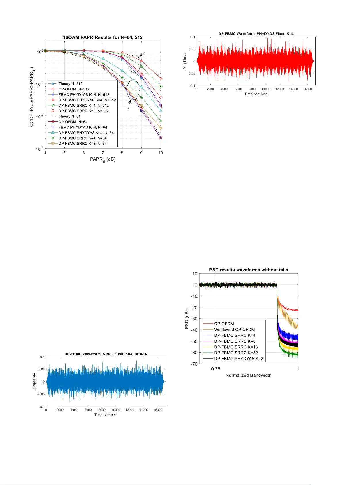
PAPR Analysis for Dual-Polarization FBMC Hosseinali Jamal, David W. Matolak Department of Electrical Engineering University of South Carolina Columbia, SC, USA hjamal@email.sc.edu, matolak@cec.sc.edu Abstract — In a recent work we proposed a new radio a ccess technique based on filter bank multi-carrier (FBMC) modulation using tw o orthogonal polarizations: dual - polarization FBMC (DP-FBMC). We showed that w ith good cross-polarization discrimination (XPD), DP-FBMC solves the intrinsic imaginary interference shortcoming of FBM C without extra processin g. DP-FBM C also has other interesting advantages over cyclic prefix orthogonal frequency -division multiplexing (CP-OFDM) and FBM C such as more rob ustness in dispersive channels, and it is also more robust to receiver carrier frequency offset (CFO) and ti ming offset (TO). In this paper w e analyze the peak to average pow er ratio (PAPR) of DP -FBMC and compare PAPR simulation results w ith that of conventional FBMC, for different prototype filters an d overlapping factors. According to the analysis and res ults, with a proper choice of prototype fil ter, DP -FBMC has co mparable PAPR to FBMC. Keywords — DP -FBMC; CP -OFDM; XPD; PAPR; CFO I. I NTRODUCTI ON It is kn own th at orthog onal fre quency division multiplex ing (OFDM) modulation with a cyclic prefix ( CP) extension decreases the s pectr al eff iciency , especial ly in highly- dispersive channels. Also, b ecause of the rectangular pulse’s fre quency response with large sidelobes , CP -OFDM thus r equires a l arge number of gua rd su bcarri ers to r educe the out- of - band power emiss ion, furthe r decreasin g spectral efficiency . As an altern ative a pproach to in crease the spectral efficiency , filte rbank m ulti-carri er (FBMC) h as bee n proposed. FBMC does not require CP and has very co mpact spectral shape due to filtering . Despite these FBMC advantages , it incurs a shortc om ing due to “intrinsic imagin ary interfer ence” in dis persive channels, the refore it requires ext ra processing to es timate and m itigate this inte rference. In [ 1], w e proposed dual- polarizati on FBMC (D P-FBMC) which can solve this intrinsic interfe rence problem . Basically by using two polarization s and d iffe rent multip lexing techniques in FBMC system s we add another dimension to suppress the intrinsi c inte rference. We show ed that transmitti ng s ymbols on tw o o rthogonal polarizat ions r educes the interfe rence by a large extent. Using different multip lexin g techniques we prop osed three different DP-FBMC approaches : Structur e I uses time-polariza tion division multiplex ing (TPDM), Struct ure II uses frequen cy- polarizati on division mu ltiplexing (FPDM), and Structur e III uses t ime-f requency- polarizati on divis ion mu ltiplexing (TFPDM). The difference in these methods is the location o f offset-QA M (OQAM) m odulated symbols in the tim e, frequency , and polarizati on domains. As described in [1 ], for DP -FBMC Struct ure I we sepa rate the ad jacent m odulated an d filtere d OQAM symbols on tw o o rthogona l polarizati ons by multiplex ing symbols in time domain. B y this approach we can remove the intrinsic interfe rence that results fr om (temporally ) adjacent sy mbols . In this pape r w e focus on Structur e I as ou r first DP-FBMC suggesti on because this structure has com plexity advantag e com pared to th e other tw o structures . DP-FBMC Structu re I has similar computational complexity and r equires the same equipment and space as conventiona l FBMC. In [1] via sim ulation results we showed that in practical cross -pola rizati on discrim ination (XPD) conditions in different chann el env ironm ents the propos ed DP -FBMC has sim ilar bit error ratio (BER) perform ance comparing to conventional FBMC and CP -OFDM, and in highly frequency-s elective channels it has better BER perform ance than F BMC. In this paper w ith som e analy sis and s imu lation results w e investigat e and com pare the peak t o average pow er ratio (PAPR) of DP-FBMC with that of conventi onal FBMC and CP -OFDM. In [1] we showed that ch oosing square-root raised cosine ( SRRC) prototype filte r for DP -FBMC Structure I we can significantly remove the intrins ic imaginary interference, and in this paper we also show that choosing the same filter with proper length , it c an al so y ield PAPR values ne arly identical to tha t of F BMC and C P-OFDM. The remainder of this paper is organized as foll ow s: in Section II we review the conventiona l FBMC and proposed dual polarization FBMC sys tem models. In Secti on III we provide the P APR analysis of DP -FBMC. In Section IV we provide sim ulation results and compare DP-FBMC and conventiona l FBMC system s ’ PAPRs for different prototype filters and num bers of subcar rier. In Section V we provide conclusions . II. D UAL P OLARIZATI ON FBMC S YSTEM M ODEL In this secti on fi rst w e descri be and review the FBMC system b ased on OFDM-OQA M modulati on [2-4]. W e then review our prop osed D P-FBMC sy stem m odel [1 ]. A. OF DM-OQAM based FBMC In the OF DM-OQ AM str ucture, we derive the real valued OQAM symbols o f subcarrier index n and s ymbol index m from complex Q AM symbols d n,l as follo ws, where l is the sample index of QA M s ymbols and m is the sample index of modulated OQAM symbols with d ouble rate o f Q AM samples, According to (1), to obtain the OQAM symbol s tructure of OFDM-OQAM the rea l and imaginary components of Q AM symbols are offset by a half symbol per iod. T hen in order to achieve the same symbol rate as complex QAM symbols, we double the rate of the OQ AM s ymbols. In ne xt step the se OQAM symbols , are filtered through prototype filter h ( t ) and then modulated across N subcarrier s and then phase shifted according to the follo wing continuous form equa tion, where h ( t ) is the finite im pulse r esponse o f a filter w ith le ngth L = KN samples , and K is defined as the overlapping factor. In the O FDM -OQAM structure the p hase of the OQAM symbols s hould be changed a ccord ing to to satisfy the real orthogonality c ondition at t he rec eiver [ 2 ], [3]. Then the filtered symbols are overlapped b y half a symbol duration, T /2. The direct form of FBMC modulati on (2) has hig h complexity , theref ore in practice similar to OFDM, fast and inverse fas t Fou rier t ransf orms (FFT, IFFT) and an extr a processing block called a polyphase network (PPN) are used (Figure 1). For m ore detail s regar ding the FBMC PPN structure and FFT implem entation refer to [3 , 4]. After IFFT processing, the subcarriers will be filtere d through the PPN netw ork. T he filtered symbols are then o verl apped by half sym bol p eriod to achieve maxim um spectral efficiency . The reverse process w ill be foll owed at re ceiver. B. DP -FBMC Figure 2 illustrate s the idea of transmitted s ignals on t wo horizontal and vertical polar ization antennas in DP -FBM C Structure I . In this Figure and the rest of the p aper we use vertical and horizontal polar izations, but we can also choose left and right -handed circular polarizations (o r o ther orthogonal pairs) as d ual orthogonal polarizations in DP - FBMC. Therefore, in this pap er we use indices H , V as horizontal and vertical p olarizations, respecti vely. To b etter understand the idea o f DP-FBMC Structure I , in Figure 3 w e depict the ti me- frequency phase -space lattice diagram to illu strate the transmitted OQAM symbols in time, frequency, a nd phase for an example of 16 subcarriers. This diagram shows ho w adjac ent symbols are separated o n two polarizations, also circles and squares indicate the π /2 phase shift on adjacent symbols to satisfy the real orthogonality [ 3 ]. Here w e define the p olarization multiplexed OQAM symbols in DP-FBM C Structu re I in ( 3). Using these multiplexed symbols we can refor mulate (2) as in the tw o equations o f (4) for each of the po larizations sig nals of th e DP -FBMC co mmunication system. III. PAPR A NALYSIS In this section first w e a nalyze the PAPR of DP -FBMC Structure I . Here we note that as long as t he statistical characteristics of each polarization’s baseband wave form are identical due to this s ymmetry we only anal yze one polarization’s wavefor m ( e.g., horizo ntal polarization). For DP -FBMC w e start and follow s imilar FBMC PAPR analysis approach in [ 5]. First the baseband eq uivalent of a discrete - (a) (.) . . . . . . . . . Overlapping ( N /2 int erval) D/A (b) Figure 1 . FBMC communication system block diagram (applicable for DP-FBCM); (a) transmitter, (b) receiver. . . . . . . A/D . . . Figure 2. DP -FBMC wireless communication link ( Structure I ). Figure 3. DP -FBMC symbols time-frequency-polarization phase- lattice ( Structure I ). t f ... ... ... ... Transmitt ed Symbols on Verti cal Ante nna Transmitt ed Symbols on Horizontal Antenna time DP-FBMC signal can be w ritten as follows f or k [0, N - 1], Then as explained in [ 7] the PAPR measure is defined as follows: Here we note that as long as the prototype filter’s length is larger than N , for a lar ge number o f frame sy mbols, ( 6) is a good ap proximation of P APR si milar to OFDM wave form. In general P APR is a random variable and for convenience we analyze the co mplementar y cu mulative distrib ution function (CCDF), t he probabilit y that PAPR exceed s a given value γ. According to ( 5), at a given discrete time k, is obtained by the summation over the N subcarriers of t he following samples, Assuming are uncorrelated with variance and zero mean, then sa mples in (7) are uncorrelated as well and we have, Th us the mean and v ariance of are independent of n . Now from ( 5) after summing all subcarriers, it is clear that, for N large enough, based on the central li mit theorem, will appr oach a co mplex Gaussian distribu ted p rocess with a zero mean and a variance o f , where denotes the variance of the r eal and imaginary p arts of (5 ), therefo re we ca n say t hat follo ws a Ra yleigh distribution. Defining and referrin g to the anal ysis in [ 5] the probability density function o f R is derived as follo ws, Now we ca n define the following for each sample k , w here is defined as the nor malized version of . According to [5 ], assuming a p rototype filter h with unit energy, it can be sho wn that = , and then, where, Now for a given PAPR value γ, we h ave, Assuming that samples of are indep endent, the n the cumulative densit y function can be written as, (14) Finally, for the co mplementary function, we have t he following CCDF express ion, According to (12) and (15), for every PAPR value, the CCDF is relate d to the num ber of subcar riers N and p rototy pe filter charact eristics . For FBMC, in [5 ] it is shown that for square-ro ot raised cosine (SRRC) filters with s mall enough roll-off factors we have nearly ident ical PAPR to OFDM. In DP -FBMC using the same SRRC filter we have a sim ilar situation, but from ( 3) we reali ze that as long as the multiplex ed polarized OQAM symbols are zero for even values o f m , then according to (8), (12), and (15) we sh ould expect d ifferen t PAPR results. In DP-FBMC Structure I , as will be show n in PAPR results because of time-division multiplex ing (TDM) natur e and temporal gaps in the waveform , P APR increases com paring to the FBMC. B ut we will show that using the SRRC filter with the suggested roll- off fact or and increasing overlappin g factor we can approach to the F BMC PA PR result. IV. S IMULATION R ESUL TS In this section fir st usin g the suggested square -root raised cosine (SRRC) and another well-kno wn filter used in PHYDYAS [6 ] project, and different K -factors we plot the simulated P APR r esults o f DP -FBMC Structure I , FBMC and CP -OFDM. In Figure 4 the impulse resp onses of pro totype filters for K =4 are shown. Figure 4. S RRC and PHYDYAS prototype filter impulse responses. For SRRC in [1 ] we sho wed that the roll -off factor equal 2/ K will res ult t he b est B ER performance co mparing to all prototype filters and we suggested this filter and roll-off factor for DP -FBMC. In the simulation results in this p aper we also use the same filter and roll -off factor for comparing PAPR results. The CCDF result s of a vector of logarit hmic PAPR val ues of P APR 0 = in the range of 4 to 10 dB for tw o values of the n umber o f s ubcarriers N = 6 4 and 5 12, are shown in Figure 5. In this Figure w e also plot the PAPR approximation result based on (15). As ca n b e seen, DP -FBMC struct ure I has slightly larger PAPR tha n FBMC. We note that using SRRC filter with suggested r oll-off factor i n DP - FBCM Structure I comparing to PHYDY AS filter has the advantage of improving the PAPR, and this is because of the larger side lobes of the SRRC impulse response in the time domain (Figure 4). Also si milar to BER improve ment shown in [1 ], the suggested SRRC filter and lar ge r K overlapp ing factors also improve the PAPR resu lts. In Figure 6, in order to better understand and show the effect of the filter on DP -FBMC waveform, we plot the waveform of one frame of DP -FBMC consisting of 32 symbols and 512 subcarriers (without tai l s) using SRRC and PHYDYAS filters and ident ical overlap ping factor K =4. As can be seen using the PHYDY AS filter yields temporal fluctuations at ever y s ymbol per iod which affect the P APR. Here we note that acco rding to o ur o ther results (not shown here) Structures II and III have PAPR similar to that of conventional FBMC and O F DM , and o nly St ructure I has worse PAPR performance due to its TDM nature. In Figure 7 we also compare the P SD of these syste ms obtained via the period ogram technique. For DP -FBMC waveforms we plo t the simulatio n res ults b efore and after removing t he two ends of t he frames for the FBMC and DP - FBMC wavefor ms (r esulting from filter tails). Thu s we truncated the first and last samples of eac h frame on DP -FBMC wavefor ms (as sho wn in Fi gure 6). In Figure 7 (a) we al so plot the PSD of CP - OFDM with and without windowing for comparison. In CP - OFDM windowing is u sed to reduce the out of band po wer. As expected, longer SRRC filters (b igger K ) also yields smaller out of band po wer. In Figure 7(b) we show the PSDs without truncation for comparison, and as expected the PHYDYAS filter has t he most compact PSD. Figure 5. CCDF vs. PAPR 0 for diff erent prototype filters (without DFT spreading), 16QAM and N =64, 512. (a) (b) Figure 6. A frame of DP-FBMC (without tails), 32 symbols, N =512; (a) SRRC filter, K =4, =0.5, (b) PHYDYAS filter, K =4 . (a) N=64 N=512 V. C ONCLU SION In this paper we investig ated the PAPR of the proposed DP -FBMC Structure I commun ication system . Via simulatio n results we showed that choosi ng proper prototy pe filters w ith appropria te length, DP-FBMC yields comparable PAPR results t o that of F BMC and C P-OFDM. R EFERENCES [1] H. Jamal, D. W. Matolak, “Dual -Polarization FBMC for Improved Performance in Wirele ss Communication Syste ms ”, in review, IEEE Transactions on Ve hicular T echnology . [2] P. Siohan, C. Siclet and N. Lacaille, “ Analysis a nd design of OFDM/OQA M sy stems based on filterbank theory ,” IEEE Transactions on Signal Processin g , v ol. 5 0, no. 5 , pp. 1 170-1183, M ay 2002. [3] B. Farhang- Boro ujeny , “OFDM Versus Filter B ank Multicarrier,” IEEE Signal Processing Magazine , vol. 28, n o. 3, pp. 92 -112, May 2011. [4] B. Farhang- Boroujeny , “Filte r Bank Multicarrier Modulation: A Wavefo rm Candidate fo r 5G and B eyond,” Hindawi, A dvances in Electrical Eng ineering , vol . 2014, Article I D 482805, 25 pages, 2014. [5] A. Skrzypczak, P . Siohan and J. P. Jav audin, “Analysis of the Peak - To - Average Power Ratio for OFD M/OQAM,” IEEE 7th Worksh op on Signal Processing Advances in Wireless Co mmunic ations , Cannes France, pp. 1-5, J uly 2006. [6] M. Bel langer, et al. “F BMC p hysical l ayer: a primer.” PHYDYA S, no. 4, Jan 2010. [Online]. Available at: http://ww w.ict- phydyas.or g/teamspace/internal-fo lder/F BMC-Primer_06-2010.pdf [7] R. B auml, R. Fischer , and J. Huber, “Red ucing the Peak- to -Ave rage Power Ratio of Mu lticarrie r Modulation b y Selected Mapping,” Elec- tronics Letters , vo l. 32, no. 22, pp. 2056-2057, Octo ber 1996. (b) Figure 7 . PSD vs. normalized bandwidth; (a) waveforms w ithout tails, (b ) waveforms with tails.
Original Paper
Loading high-quality paper...
Comments & Academic Discussion
Loading comments...
Leave a Comment