Localization and Tracking of an Acoustic Source using a Diagonal Unloading Beamforming and a Kalman Filter
We present the signal processing framework and some results for the IEEE AASP challenge on acoustic source localization and tracking (LOCATA). The system is designed for the direction of arrival (DOA) estimation in single-source scenarios. The propos…
Authors: Daniele Salvati, Carlo Drioli, Gian Luca Foresti
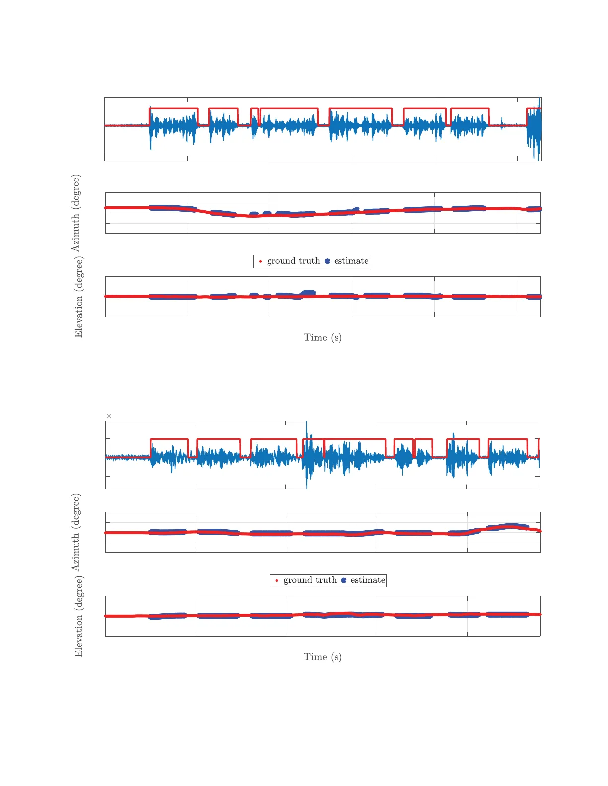
LOCA T A Challenge W orkshop, a satellite ev ent of IW AENC 2018 September 17-20, 2018, T okyo, Japan LOCALIZA TION AND TRA CKING OF AN A COUSTIC SOURCE USING A DIA GON AL UNLO ADING BEAMFORMING AND A KALMAN FIL TER Daniele Salvati, Carlo Drioli, Gian Luca F or esti Department of Mathematics, Computer Science and Physics Uni versity of Udine via delle Scienze, 206, 33100 Udine, Italy ABSTRA CT W e present the signal processing framework and some results for the IEEE AASP challenge on acoustic source localization and track- ing (LOCA T A). The system is designed for the direction of ar- riv al (DO A) estimation in single-source scenarios. The proposed framew ork consists of four main building blocks: pre-processing, voice activity detection (V AD), localization, tracking. The signal pre-processing pipeline includes the short-time Fourier transform (STFT) of the multichannel input captured by the array and the cross power spectral density (CPSD) matrices estimation. The V AD is calculated with a trace-based threshold of the CPSD matrices. The localization is then computed using our recently proposed di- agonal unloading (DU) beamforming, which has low-complexity and high resolution. The DOA estimation is finally smoothed with a Kalman filer (KF). Experimental results on the LOCA T A dev el- opment dataset are reported in terms of the root mean square er- ror (RMSE) for a 7-microphone linear array , the 12-microphone pseudo-spherical array integrated in a prototype head for a hu- manoid robot, and the 32-microphone spherical array . Index T erms — Acoustic source localization, speaker tracking, diagonal unloading beamforming, LOCA T A, Kalman filter , micro- phone array . 1. INTR ODUCTION The aim of an acoustic source localization and tracking system is to estimate the position of sound sources in space by analyzing the sound field with a microphone array , a set of microphones arranged to capture the spatial information of sound. Speaker spatial local- ization/tracking using microphone arrays is of considerable interest in applications of teleconferencing systems, hands-free acquisition, human-machine interaction, recognition, and audio surveillance. In this paper , we present the signal processing framework for the IEEE AASP challenge on acoustic source localization and track- ing (LOCA T A) [1]. W e also present some performance results re- lated to the LOCA T A dev elopment dataset. The proposed local- ization and tracking system is designed for the direction of arriv al (DO A) estimation in single-source scenarios. The localization algo- rithm is based on diagonal unloading (DU) beamforming, recently introduced in [2]. Broadband DU localization beamformer is com- puted in the frequency-domain [3] by calculating the steered re- sponse power (SRP) on each frequency bin and by summing the narrowband components with the incoherent frequency fusion [4]. The tracking is performed with a Kalman filter (KF) [5]. 2. METHOD The proposed system consists of four main building blocks: • pre-processing; • voice activity detection (V AD); • localization; • tracking. The organization of the signal processing components is illustrated in Figure 1. 2.1. Pr e-Processing The signal pre-processing pipeline includes the short-time Fourier transform (STFT) of the multichannel input captured by the array x m ( t ) ( m = 1 , 2 , . . . , M , where M is the number of microphones). It can be expressed as X m ( k , f ) = l = L 2 − 1 X l = − L 2 w ( l ) x m ( l + kR ) e − j 2 πf l L , k = 0 , 1 , . . . , (1) where k is the frame time index, f is the frequency bin, w ( l ) is the analysis windo w , L is the size of the fast Fourier transform (FFT), and R is the hop size. After the frequency-domain transformation, the cross power spectral density (CPSD) matrices Φ ( k , f ) of the considered fre- quency range [ f min , f max ] are estimated through the a veraging of the array signal blocks [6] b Φ ( k , f ) = 1 N N − 1 X k n =0 x ( k − k n , f ) x H ( k − k n , f ) , f = f min , f min + 1 , . . . , f max , (2) where N is the number of frames for the averaging, H denotes the conjugate transpose operator , and x ( k , f ) = [ X 1 ( k , f ) , X 2 ( k , f ) , . . . , X M ( k , f )] T , (3) where T denotes the transpose operator . 2.2. V AD The V AD used herein is based on the trace of the CPSD matrices that is related on the DU beamforming. The trace of a CPSD matrix is equivalent to the sum of the eigen values of the matrix, i.e., it LOCA T A Challenge W orkshop, a satellite ev ent of IW AENC 2018 September 17-20, 2018, T okyo, Japan Pr e -Pr ocessing VAD Localiz ation Sound Acq uisition STFT a nd CPSD Matrices Trace-bas ed Thre s hold Diagonal Unload ing Bea m form ing Microphone Array Trac k ing Kalman Fi lter DOA Es t i mation Azimu t h and Elevat ion Figure 1: Schematic diagram of the proposed system. represents the overall power of the array . The source detection is hence calculated as V AD ( k ) = ( 1 , if P f max f = f min tr [ b Φ ( k , f )] > η , 0 , otherwise , (4) where tr [ · ] is the operator that computes the trace of a matrix, and η is a given threshold. The parameter η was empirically set to the value allo wing to effecti vely detect the source acti vity . 2.3. Localization The acoustic source DOA estimation method is a low complexity and robust beamformer based on a DU transformation of the covari- ance matrix in volv ed in the con ventional beamformer computation to exploit the high resolution subspace orthogonality property . The method is illustrated in details in [2]. The transformation, on which the DU method is based, is ob- tained by subtracting an opportune diagonal matrix from the CPSD matrix b Φ ( k , f ) of the array output vector . As a result, the DU beam- forming removes as much as possible the signal subspace from the cov ariance matrix and provides a high resolution beampattern. In practice, the design and implementation of the DU transformation is simple and effectiv e, and is obtained by computing the matrix (un)loading factor . The broadband SRP is defined as [2, 4] P ( k, Ω d ) = f max X f = f min P DU ( k , f , Ω d ) || g ( k , f ) || ∞ , (5) where Ω d = [ θ d , φ d ] ( θ d and φ d are the azimuth and elev ation angles) is the steering direction, || · || ∞ denotes the Uniform norm, i.e., the maximum value of the v ector g ( k , f ) = [ P DU ( k , f , Ω 1 ) , P DU ( k , f , Ω 2 ) , . . . , P DU ( k , f , Ω D )] , (6) which contains all the narrowband SRP for the considered search direction D , and the narrowband DU response po wer beamforming P DU ( k , f , Ω d ) is defined as P DU ( k , f , Ω d ) = 1 a H ( f , Ω d )[ tr [ b Φ ( k , f )] I − b Φ ( k , f )] a ( f , Ω d ) , (7) where a ( f , Ω d ) is the array steering vector for the direction Ω d , and I is the identity matrix. Note that the unloading parameter is computed with the trace operation of the CPSD matrices. This so- lution guarantees that the transformed PSD matrix Φ DU ( k , f ) = [ tr [ b Φ ( k , f )] I − b Φ ( k , f )] has the attenuation of the signal subspaces with respect to the noise subspace, and hence the high resolution orthogonality is exploiting, even if partially , since the transformed PSD matrix is affected by a certain amount of signal subspace [2]. The array steering vector depends on the array geometry . Note that for the linear array the steering direction is giv en only by the az- imuth angle. Then, the DO A estimate of the source is obtained by ˆ Ω s ( k ) = argmax Ω d [ P ( k, Ω d )] , d = 1 , 2 , . . . , D . (8) 2.4. T racking The KF [5] is an optimal recursi ve Bayesian filter for linear systems observed in the presence of Gaussian noise. The filter equations can be divided into a prediction and a correction step. The state of the process is giv en by y ( k ) = [ Ω ( k ) , v θ ( k ) , v φ ( k )] T , (9) where v θ ( k ) and v φ ( k ) are the velocities. In the prediction step the update equations are y p ( k ) = Ay ( k − 1) , (10) P p ( k ) = AP ( k − 1) A T + BQB T , (11) where A = 1 0 dt 0 0 1 0 dt 0 0 1 0 0 0 0 1 , (12) B = 0 . 5 dt 2 0 0 0 . 5 dt 2 dt 0 0 dt , (13) Q = σ 2 q 0 0 σ 2 q , (14) with σ 2 q being the variance of the process error , dt = RN /f s the time elapsed between DO A estimations, f s the sampling rate. The filter is initialized with the state cov ariance matrix P ( k i ) = BQB T and the state y ( k i ) = [ ˆ Ω s ( k i ) , 0 , 0] T , where k i is the first time frame in which the V AD( k i ) has value 1 and V AD( k i -1)=0. After the prediction step, the Kalman gain is calculated as K = P p ( k ) C T ( CP p ( k ) C T + R ) − 1 , (15) LOCA T A Challenge W orkshop, a satellite ev ent of IW AENC 2018 September 17-20, 2018, T okyo, Japan where C = 1 0 0 0 0 1 0 0 , (16) R = σ 2 r 0 0 σ 2 r , (17) with σ 2 r being the v ariance of the measurement error . In the correc- tion step the measurement update equations are y ( k ) = y p ( k ) + K ( ˆ Ω s ( k ) − Cy p ( k )) , (18) P ( k ) = ( I − K C ) P p ( k ) . (19) Hence, after the correction step the filtered DO A estimation ˆ Ω EKF s ( k ) = Ω ( k ) is obtained. 3. EXPERIMENT AL RESUL TS W e present some experimental results on the LOCA T A dev elopment dataset to sho w the performance of the proposed frame work in the single-source scenario with: • static loudspeaker and static array (task 1); • moving speaker and static array (task 3); • moving speaker and moving array (task 5). W e tested the system with the distant talking interfaces for control of interacti ve TV (DICIT) array by considering a 7-microphone lin- ear subarray ([4 5 6 7 9 10 11]) taking into account the far -field model, the 12-microphone pseudo-spherical array integrated in a prototype head for a humanoid robot array , and the 32-microphone eigenmike spherical array . The system setup is implemented with the following parameters: • sampling rate: 48 kHz; • STFT window: Hann function w ( l ) ; • FFT size: L = 2048 samples; • hop size: R = 512 samples; • number of frames for CPSD estimation: N = 25 ; • frequency range: [ f min , f max ]=[80,8000] Hz; • V AD threshold: η = 200 (linear array), η = 50 (robot head), η = 10 (eigenmike); • spatial resolution: 1 de gree (linear array , D = 181 ), 5 degrees (robot head and eigenmike, D = 2701 ); • DOA estimation time period: dt = 0 . 2667 s; • KF parameters: σ 2 q = 10 − 3 , σ 2 r = 10 − 4 . The signal processing framework has been implemented using Mat- lab R2017a. W e used our own implementation for the KF . The performance was assessed in terms of the root mean square error (RMSE). T able 1 shows the DOA estimation results for each task and each recording. The azimuth angle was e valuated for the linear array , while both azimuth and elev ation angles was considered for the robot head and eigenmike array . Three examples of detection, localization and tracking are depicted in Figures 2, 3, 4. Figure 2 shows the performance of the linear array for the task 1 (static loudspeaker , static array) and recording 3. Figure 3 shows the per - formance of the robot head array for the task 3 (moving speaker, static array) and recording 2. Figure 4 shows the performance of the eigenmike array for the task 5 (moving speaker , moving array) and recording 1. The top plot shows the wav eform of channel 1 with the speaker acti vity (red line). 4. CONCLUSIONS The signal processing framework based on a DU beamforming and a KF for the IEEE AASP LOCA T A challenge has been presented. W e described the four main b uilding blocks (pre-processing, V AD, localization, tracking) for the DOA estimation of a single source. W e showed some results with the LOCA T A dev elopment dataset using a linear array , the robot head pseudo-spherical array , and the eigenmike spherical array . 5. REFERENCES [1] H. W . L ¨ ollmann, C. Evers, A. Schmidt, H. Mellmann, H. Bar- fuss, P . A. Naylor, and W . Kellermann, “The LOCA T A chal- lenge data corpus for acoustic source localization and tracking, ” in Pr oceedings of the IEEE Sensor Array and Multichannel Sig- nal Pr ocessing W orkshop , 2018. [2] D. Salv ati, C. Drioli, and G. L. Foresti, “ A lo w-complexity ro- bust beamforming using diagonal unloading for acoustic source localization, ” IEEE/A CM T ransactions on Audio, Speech, and Language Pr ocessing , vol. 26, no. 3, pp. 609–622, 2018. [3] J. Benesty , J. Chen, Y . Huang, and J. Dmochowski, “On microphone-array beamforming from a MIMO acoustic signal processing perspecti ve, ” IEEE T ransactions on Audio, Speech, and Language Pr ocessing , vol. 15, no. 3, pp. 1053–1065, 2007. [4] D. Salvati, C. Drioli, and G. L. Foresti, “Incoherent frequency fusion for broadband steered response power algorithms in noisy en vironments, ” IEEE Signal Pr ocessing Letters , vol. 21, no. 5, pp. 581–585, 2014. [5] R. E. Kalman, “ A new approach to linear filtering and predic- tion problems, ” J ournal of Basic Engineering , v ol. 82, pp. 35– 45, 1960. [6] L. Zhang, W . Liu, and L. Y u, “Performance analysis for finite sample MVDR beamformer with forward backward process- ing, ” IEEE T ransactions on Signal Processing , vol. 59, no. 5, pp. 2427–2431, 2011. LOCA T A Challenge W orkshop, a satellite ev ent of IW AENC 2018 September 17-20, 2018, T okyo, Japan T able 1: The RMSE (degree) of the localization performance on the LOCA T A dev elopment dataset. Linear array Robot head Eigenmike Azimuth Azimuth Elevation Azimuth Elev ation task 1 recording 1 0.972 1.649 2.447 5.863 2.444 recording 2 5.096 0.038 1.013 6.676 6.054 recording 3 1.437 2.998 1.980 7.491 5.203 task 3 recording 1 6.480 3.596 2.326 9.939 3.232 recording 2 9.638 4.583 3.798 14.244 4.348 recording 3 4.355 2.880 2.807 9.370 5.804 task 5 recording 1 4.912 2.338 1.818 4.433 3.100 recording 2 21.196 30.217 11.333 32.942 5.738 recording 3 3.086 23.010 7.782 10.203 3.473 0123456 -90 0 90 0123456 -0.02 0 0.02 Task1, recording 3, linear array Figure 2: The performance of the proposed system with the 7-microphone DICIT linear subarray for task 1 (static loudspeaker , static micro- phone array , recording 3). LOCA T A Challenge W orkshop, a satellite ev ent of IW AENC 2018 September 17-20, 2018, T okyo, Japan 0 5 10 15 20 25 -180 -90 0 90 180 0 5 10 15 20 25 0 90 180 0 5 10 15 20 25 -0.01 0 0.01 Task3, recording 2, robot head Figure 3: The performance of the proposed system with the robot head array for task 3 (moving speaker , static microphone array , recording 2). 0 5 10 15 20 -180 -90 0 90 180 0 5 10 15 20 0 90 180 0 5 10 15 20 -5 0 5 10 -3 Task5, recording 1, eigenmike Figure 4: The performance of the proposed system with the eigenmik e array for task 5 (moving speak er, moving microphone array , recording 1).
Original Paper
Loading high-quality paper...
Comments & Academic Discussion
Loading comments...
Leave a Comment