Cellular UAV-to-X Communications: Design and Optimization for Multi-UAV Networks
In this paper, we consider a single-cell cellular network with a number of cellular users (CUs) and unmanned aerial vehicles (UAVs), in which multiple UAVs upload their collected data to the base station (BS). Two transmission modes are considered to…
Authors: Shuhang Zhang, Hongliang Zhang, Boya Di
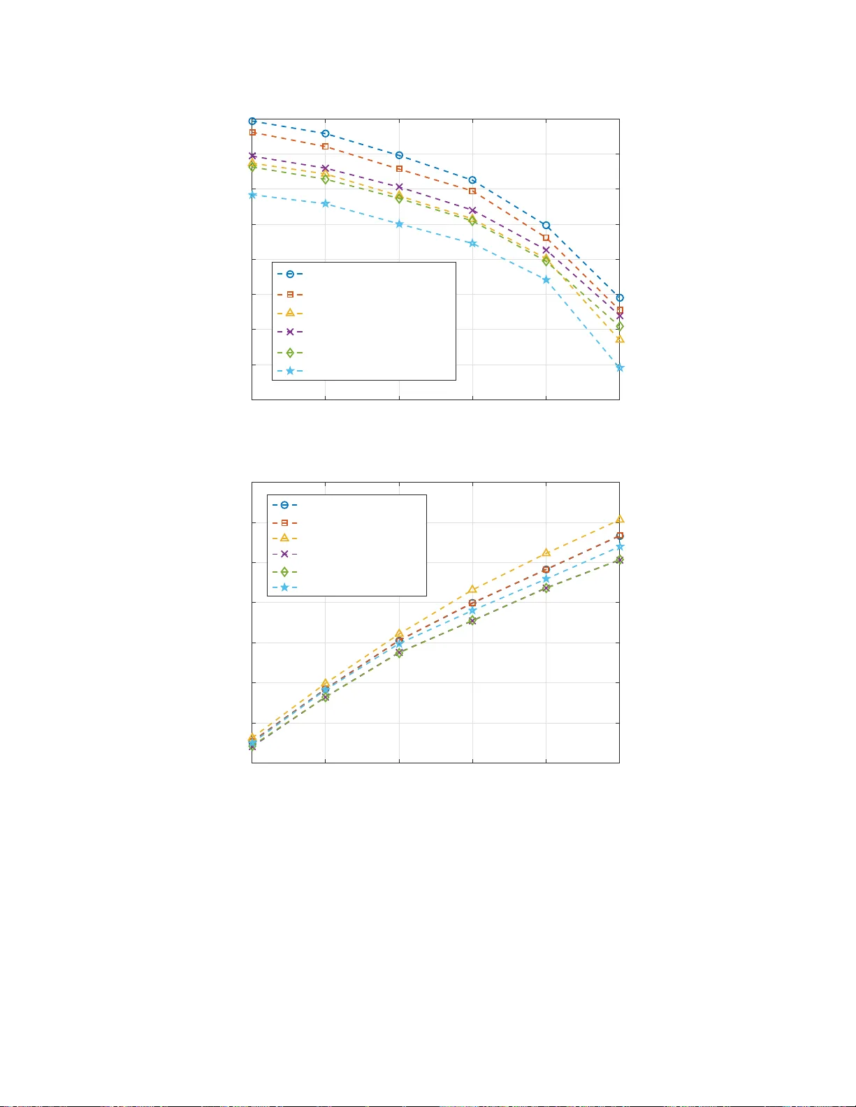
1 Cellular U A V -to-X Communications: Design and Optimizati on for Multi-U A V Networks Shuhang Zhang, Hongliang Zhang, Student Member , IEEE , Bo ya Di, Student Member , IEEE , and Lingyang Song, Senior Member , IEEE Abstract In this paper, we consider a single- cell cellular ne twork w ith a numb er of cellular users (CUs) and unmann ed aerial vehicles (U A Vs), in wh ich multiple U A Vs u pload the ir collected data to the base station (BS). T wo transmission modes are considered to support th e multi-U A V com m unication s, i. e., U A V -to-infrastructu re (U2I) and UA V -to- U A V (U2U) co mmunica tio ns. Specifically , the UA V with a high signal to noise ra tio (SNR) fo r the U2 I link up lo ads its collected data directly to the BS th rough U2I co mmunicatio n, wh ile the UA V with a low SNR for th e U2I link can tran smit data to a nearby U A V throug h under laying U2U communicatio n fo r the sake of qu ality of service. W e first pr o pose a cooper a tive U A V sense- and-send protocol to en able the U A V -to -X comm unication s, and then formulate the subchann el allocation and U A V speed o ptimization p r oblem to maximize the uplink sum-rate. T o solve this NP-hard prob lem effi ciently , we decoup le it into th ree sub-pr oblems: U2 I and cellular user (CU) subchan nel allocation, U2 U subchan nel allocation, and U A V speed optimization. An iterati ve subchann el allocation and speed op timization a lg orithm (ISASO A) is propo sed to solve these sub- problem s jo intly . Simulation results show that the p roposed ISASOA can u pload 1 0 % mor e data than the greedy algorith m . Index T erms U A V -to-X commu nication, sense-and-sen d protocol, speed o ptimization, subc h annel alloc ation. The authors are wi th the School of E lectronics Engineering and Computer Science, Peking University , Beijing, China. Email: { shuhangzh ang, hongliang.zhang, diboya, lingyan g.song } @pk u.edu.cn. 2 I . I N T RO D U C T I O N Unmanned aerial vehicle (U A V) is an emer ging facility which has been ef fecti ve ly applied i n military , public, and civil appli cations [1]. According to BI Intelligence’ s report, more than 29 million U A Vs are expected to be put in t o us e in 2021 [2]. Among these applications, t he use of U A V to perform sensing has been o f particular i nterest owing to its significant advantages, such as t h e ability of on-demand flexible deployment, larger service coverage compared with the conv enti onal fixed sensor nodes, and additional design degrees of freedom by exploiting its high U A V mo b ility [3], [4]. Recently , U A Vs with cameras or sensors ha ve entered th e daily liv es to execute various sensing tasks , e.g. air q u ality in d ex monitoring [5], autonom o us target detection [6], precision agricul ture [7], and water st ress quantification [8]. The s ensory data needs to be transmitted to the server for further processin g , th ereby p o sing hig h upli nk rate requirement on the U A V communication network. Driv en by such real-time requirement s, the upcoming network is committed to support U A V communication , where the collected data can be effec tiv ely t ransm itted [9]. Unlike t he con ven- tional ad hoc sensor network, the sensory data can be transmitted to th e 5G networks directly in a centralized way [10], whi ch can greatly improve the quality of U A V comm unications [11]. In this p aper , we study a single cell cellular network with a numb er o f cellular users (CUs) and U A Vs, where each UA V m oves along a p re-determin ed trajectory to col l ect data, and then uploads these data to the base stati o n (BS ). Howe ver , some U A Vs may l ocated at the cell edge, and the signal t o noise ration (SNR) o f their communication l inks to the BS are l ow . T o provide a satisfactory data rate, we enable these U A Vs to transmit the sensory d ata to the U A Vs with high SNR for the comm unication l ink to the BS as relay . The relaying U A Vs s ave the recei ved data in their caches and upl o ad th e data to the BS in the following time slots as described in [12]. Specifically , the UA V transmissi ons can be supported by two basic modes, namely U A V -to- infrastructure (U2I) and U A V -t o-U A V (U2U) transmissions. Th e ov erlay U2 I transmission offers direct l i nk from U A Vs wi th high SNR to the BS, and thus provides a high data rate [13], [14]. In U2U transm ission, a U A V with l ow SNR for the U2 I lin k can s et up direct communicatio n links t o t he hi gh U2I SNR U A Vs bypassing the network infrastructure and s h are t he sp ectrum with the U2I and CU transm issions, whi ch provides a spectrum-efficient method to sup p ort the data relaying p rocess [15]. Due to the high mobility and long transmission di stance of the sensing U A Vs, it is not tri vial to 3 address the following issues. Firstly , since the U2U transmissi o ns underlay the spectrum resources of the U2I and CU transm issions, the U2I and CU transmiss i ons m ay be interfered by the U2U transmissio n s when sharing th e same subchannel. Correspondingl y , the U2U transmi ssions are also interfered by t he U2I, CU, and U2U lin ks on the same subchannel. Moreover , different channel models are util ized for the U2I, U2U , and CU transmissio n s due to the dif ferent characteristics of air-to-ground, air- to-air , and ground-t o -ground comm unications. Therefore, an efficient spectrum allocation algorithm is required to manage the mutual interference. Secondly , to complete the dat a collection of t he sensing tasks giv en ti m e requirem ent s, the U A V speed optimizat i on is necessary . Thirdly , to av oid the data loss and provide a relatively high data rate for the UA Vs wi t h low SNR for the link to the BS, an efficient commun ication metho d is essential. In summary , the resource allocation schemes, U A V speed, and U A V transmi ssion protocol should be properly desig n ed to support the U A V -to-X com munications. In the literature, some works on t h e U A V comm unication network hav e been st udied, in which U A Vs work as relays or BSs. In [16], t h e authors studied a 3-D U A V -BS placement to maximize the num ber of covered users wi th d iffe rent quali t y-of-service requirements . In [17], the deployment of a U A V as a flying BS used t o provide the fly wireless commun ications was analyzed. In [18], the U A V was proposed to work as a mobile BS which collected data from fixed sensor nodes o n the ground. A trajectory design and powe r control algorit hm was introduced for a U A V relay network in [19] to i mprove the reliability of transm issions. The work [20] inv esti gated the s cenario where U A Vs served as flying BSs to provide wireless service to ground users, and optimized the downlink d ata rate and U A V hover duration. In [21], t he authors proposed a hybrid network archit ecture with the use of U A V as a BS, which flies cyclically along the cell edge to serve the cell-edge users. Unlike most of the p re vious works whi ch ty pically treat U A Vs as relays or BSs, in our work the U A Vs that relay the data from o t her U A V s also have their own sensing tasks, i .e. we consider the U A Vs as flying mobile terminals in t h e UA V sensing network. The m ain contributions of this paper can be summ arized below . (1) W e con s truct a U A V communicatio n network, where the U A Vs can either upload the collected data via U2I com m unications directly or send to other U A Vs by U2U commu n ications. A cooperativ e U A V sense-and-send protocol is proposed t o enabl e these communications. (2) W e formulate a jo int subchannel allocation and U A V speed opti m ization problem to m axi - mize t he up l ink sum -rate of the network. W e then prove that t he problem is NP-hard, and decompose it into three s ub-problems: U2I and CU subchannel allocation, U2U subchannel 4 allocation, and U A V speed opt imization. An ef ficient iterative subchannel allocation and speed optimization algo rithm (ISASO A) is proposed to s o lve the sub-problems iterati vely . (3) W e compare the propo sed algo ri t hm with a greedy algorithm in sim ulations. The results show that th e propos ed ISASO A outp erforms t h e greedy algorithm by about 10% in t erms of the upl ink sum-rate. The rest of this p aper is organized as follows. In Section II, we present the system model of the U A V sensing network. A cooperativ e U A V sense-and-send protocol is proposed in Section III for the data collecti o n and U A V -to-X communi cations. In Section IV , we formulate the uplink sum-rate maxim ization problem b y opti m izing the subchannel all o cation and U A V sp eed j o intly . The ISASO A is proposed in Section V , followed b y the correspondi ng analys i s. Simulation results are presented in Section VI, and finally we conclud e the paper i n Section VII. I I . S Y S T E M M O D E L In this sectio n , we first describe th e working scenario, and then introdu ce t he data transm ission of this network. Finally , we present the channel mo d els for U2I, U2U, and CU transmission s, respectiv ely . A. Scenario Description W e consider a s i ngle cell cellular network as s hown in Fig. 1, which consi sts of one BS, M CUs, denoted by M = { 1 , 2 , · · · , M } , and N U A Vs, denoted by N = { 1 , 2 , · · · , N } . The U A Vs collect various required data with their sensors in each t ime slot , and the data will be sent to the BS for further processing. CU q CU p BS UAV j UAV i UAV m UAV n U2I Link U2U Link Cellular User Link Potential Interference Fig. 1. System model. W e denot e the locati on of U A V i in time sl ot t by l i ( t ) = ( x i ( t ) , y i ( t ) , h i ( t )) , and the location of th e BS by (0 , 0 , H ) . Each U A V moves along a pre-determined trajectory . Let v i ( t ) be the velocity of U A V i in time slot t . The location of U A V i in time slot t + 1 is giv en as l i ( t + 1) = 5 l i ( t ) + v i ( t ) · ω i ( t ) , wh ere ω i ( t ) is t h e trajectory direction of U A V i in time slot t . D u e to the mechanical lim i tation, th e velocity o f a U A V is no more than v max 1 . Let L i be the lengt h of U A V i ’ s trajectory . W ith proper transmission rate requirements, t h e U A Vs are capable to up load the sens o ry data to th e BS with low l atency . Therefore, the task compl etion tim e of a UA V can be defined as the time that it costs to compl ete its moving along the trajectory , wh ich is determined by it s s peed in each time slot . For timely data collection , th e task completio n time of each U A V is required to be no more than T time slots, i.e., P T t =1 k v i ( t ) k ≥ L i , ∀ i ∈ N . In time slot t , t he di s tance between U A V i and U A V j is sho wn as d i,j ( t ) = q x i ( t ) − x j ( t ) 2 + y i ( t ) − y j ( t ) 2 + h i ( t ) − h j ( t ) 2 , (1) and the di stance between U A V i and BS is expressed as d i,B S ( t ) = q x i ( t ) 2 + y i ( t ) 2 + h i ( t ) − H 2 . (2) The lo cation of CU i is given as x c i , y c i , h c i . In this paper , we assume that the locatio ns of the CUs are fixed in diff erent time slots, as the m obility of the CUs are much lower than that of the U A Vs. Therefore, the distance between CU i and U A V j can be denoted by d c i,j ( t ) = q x c i ( t ) − x j ( t ) 2 + y c i ( t ) − y j ( t ) 2 + h c i ( t ) − h j ( t ) 2 , (3) and the di stance between U A V i and BS can be shown as d c i,B S ( t ) = q x c i ( t ) 2 + y c i ( t ) 2 + h c i ( t ) − H 2 . (4) B. Data T ransmi ssion In this part, we give a brief i ntroduction to the data transmission of t his network. T o provide a hig h data transmissio n rate for all th e U A Vs, we distingui sh the U A Vs with differ ent quality of service for the link to the BS into different transmission schem es. There are two types of U A V transm ission schemes in this network, namely U2I t ransmission and U2 U transmission 2 . A U A V may either perform U2I transmission or U2U transmissi on in one time sl ot. The criterion of adopting U2I or U2U transmi ssion is give n below . 1 W e consider the UA Vs as rotary wing U A Vs which can ho ver in the air for some time slots. The rotary wing UA Vs can mov e with the velo city of [0, v max ] in any time slot. 2 W e assume that the CUs only transmit data to the BS, and the de vice-to-device transmission between CUs is out of the scope of this network. 6 1) U2I T ransmission : A U A V with h i gh SNR for the link to the BS performs U2I t ransmission in the network. It uploads its collected data to t he BS directly over the assign ed s ubchannel. 2) U2U T ransmission : A U A V with l ow SNR for the link to the BS performs U2U commu- nication to t rans m it the collected data to a U A V in U2I transmissio n scheme. Let N h ( t ) = { 1 , 2 , · · · , N h ( t ) } and N l ( t ) = { 1 , 2 , · · · , N l ( t ) } be the set of U A V s that perform U2I and U2U transm issions in time slot t , respectively , with N = N h ( t ) ∪ N l ( t ) . For the U A Vs in N h ( t ) , th ey send the d at a to the BS by U2I transmi ssions overlaying the cellular ones. For the U A Vs in N l ( t ) , the SNR of the direct communication lin k s are l ow , wh i ch are diffi cult to provide high data rates to support timely data upload via U2I transmissio n s. Therefore, the U A Vs send the collected data to the neighbouring U A Vs with hig h SNR for the U2I link via U2U transmissio n s, which work as an underlay of the U2I and CU transmissions, and the data will be sent to the BS later by the relaying U A Vs. Th e sensi ng and transmission are performed simultaneous l y by each U A V , and the detailed procedure wi ll be elabo rated in Section III. The transm ission bandwidt h of this network is di v i ded into K o rt h ogonal subchannel s , denoted by K = { 1 , 2 , · · · , K } , and the U2U transmis sion U A Vs work in an u nderlay mode, i . e., they reuse the s p ectrum resources with the U2I and CU transmis s ions. It is worthwhile to menti on that a single U A V can perform U2I transmiss ion and U2U reception ov er diffe rent su bchannels simultaneous l y . For the sake of transm ission quality , we assume that a subchannel can serve at most one U2I or CU link, but multiple U2U links in one time slot. In addi tion, to guarantee fairness among the users, we also assume that each transmi ssion li nk can be allocated to no more than χ max subchannels. In time slot t , we define a ( N h + M ) × K binary U2I and CU subchann el pairing matrix Φ ( t ) = [ φ i,k ( t )] , and a N l × K binary U2U subchannel pairing matrix Ψ ( t ) = [ ψ i,k ( t )] , to describe th e resource allocation for CU, U2I and U2U t ransmission s , respecti vely . F o r i ≤ N h , φ i,k ( t ) = 1 when subchannel k is assign ed to U A V i for U2I transmission, otherwise φ i,k ( t ) = 0 . For i > N h , φ i,k ( t ) = 1 when sub chann el k is assigned to CU i − N for CU transmissio n , otherwise φ i,k ( t ) = 0 . Like wise, t he value of ψ i,k ( t ) = 1 when subchannel k is assigned to U A V i for U2U transm ission, otherwise ψ i,k ( t ) = 0 . W e denote ξ i,j ( t ) = 1 when U A V i performs U2U transm ission with U A V j in t i me s l ot t , and ξ i,j ( t ) = 0 otherwise. In order to av oi d the hig h communication lat ency for the U A Vs, the data rate of each U2U communi cation link sho uld be no less R 0 , i.e. P K k =1 ψ i,k ( t ) R k i,j ( t ) ≥ R 0 , ∀ i, j ∈ N , ξ i,j = 1 . 7 C. Channel Mod el In thi s subsection , we introdu ce the channel model i n th is network. The channel mo d els of the U2I, CU, and U 2 U transmission s are different, due to the different characteristics in LoS probability and ele vation angel, which will be introduced as fol lows, respectiv ely . 1) U2I Channel Model: W e use th e air-to-ground propagation model which i s proposed in [23]–[25] for the U2I transmissi on. In time slot t , t he Lo S and NLoS pathloss from UA V i to the BS i s g iv en by P L LoS,i ( t ) = L F S, i ( t ) + 2 0 log( d i,B S ( t )) + η LoS , (5) P L N LoS,i ( t ) = L F S, i ( t ) + 2 0 log( d i,B S ( t )) + η N LoS , (6) where L F S, i ( t ) is the free space pathlos s g iven by L F S, i ( t ) = 20 log( f ) + 20 log( 4 π c ) , and f is the s ystem carrier frequency . η LoS and η N LoS are add itional attenuatio n factors due to the LoS and NLoS connections . Consid ering t he antennas on U A Vs and th e BS placed vertically , the probability of LoS connecti on is given by P LoS,i ( t ) = 1 1 + a exp( − b ( θ i ( t ) − a )) , (7) where a and b are constant s which depend on the en vironm ent , and θ i ( t ) = sin − 1 (( h i ( t ) − H ) /d i,B S ( t )) is the ele vation angle. The a verage pathlos s in dB can t hen be expressed as P L avg ,i ( t ) = P LoS,i ( t ) × P L Los,i ( t ) + P N LoS,i ( t ) × P L N LoS,i ( t ) , (8) where P N LoS ( t ) = 1 − P LoS ( t ) . The av erage received power of BS from U A V i over its pai red subchannel k is giv en by P k i,B S ( t ) = P U 10 P L av g,i ( t ) / 10 , (9) where P U is t he transmit p ower of a U A V or CU over one subchannel. Since each subchannel can be ass igned to at most one U2I or CU link, the interference t o the U2I transmissi ons only comes from the U2U t ransmission s due to s pectrum sharing. When U A V i performs U2I t ransmission over subchannel k , the U2 U interference is expressed as I k ,U 2 U ( t ) = N l X j =1 ψ j,k ( t ) P k j,B S ( t ) . (10) Therefore, the sig nal t o interference plu s n o ise ratio (SINR) of the BS over subchannel k is giv en by γ k i,B S ( t ) = P k i,B S ( t ) σ 2 + I k ,U 2 U ( t ) , (11) where σ 2 is the variance of additive white Gaussian noise (A WGN) with zero m ean. The data rate that BS receive s from UA V i over subchannel k is shown as R k i,B S ( t ) = log 2 (1 + γ k i,B S ( t )) . (12) 8 2) CU Channel Model: W e util i ze the macrocell pathloss mod el as proposed in [26]. For CU i , t h e pathloss in dB can be expressed by P L k i,C ( t ) = − 55 . 9 + 38 log( d c i,B S ( t )) + (24 . 5 + 1 . 5 f / 925) lo g( f ) . (13) When CU i transm its si gnals to BS, the receive d p ower is expressed as P k i,C ( t ) = P U 10 P L k i,C ( t ) / 10 . (14) W e denote the set of UA Vs that share subchannel k wi th CU i b y U i = { m | ψ m,k ( t ) = 1 , ∀ m ∈ N e } , and t h e recei ved po wer at the BS ove r subchann el k is sh own as y k i,j ( t ) = q P k i,C ( t ) + X m ∈ U i q P k m,B S ( t ) + n k j ( t ) , (15) where n k j ( t ) is the A WGN with zero mean and σ 2 var iance. Therefore, the receiv ed sign al at the BS over subchann el k can be given by γ k i,B S ( t ) = P k i,C ( t ) σ 2 + I k ,U 2 U ( t ) , (16) where I k ,U 2 U ( t ) = P N j =1 ψ j,k ( t ) P k j,B S ( t ) is the U2U interference. The data rate for CU i over subchannel k is expressed as R k i,B S ( t ) = log 2 (1 + γ k i,B S ( t )) . (17) 3) U2U Chann el Model: For U2U com munication, free-space channel model is utili zed. When U A V i transmits signals t o U A V j over subchannel k , the recei ved power at U A V j from U A V i is expressed as P k i,j ( t ) = P U G ( d i,j ( t )) − α , (18) where G is the constant po wer gains factor intro d u ced by amplifier and antenn a, and ( d i,j ( t )) − α is the pathlo s s. Define the set of U A Vs and CUs that share subchannel k with U A V i as W i = { m | ψ m,k ( t ) = 1 , ∀ m ∈ N e \ i } ∪ { m | φ m,k ( t ) = 1 } . The receiv ed signal at UA V j over su b channel k is then giv en by y k i,j ( t ) = q P k i,j ( t ) + X m ∈ W i q P k m,j ( t ) + n k j ( t ) , (19) where P k m ( t ) is the receive d power at U A V j from the U A Vs and CUs in W i , and n k j ( t ) is the A WGN with zero mean and σ 2 var iance. The interference from U A V m to U A V j over subchannel k is shown as I k m,U AV ( t ) = ( φ m,k ( t ) + ψ m,k ( t )) P U ( d m,j ( t )) − α . (20) According to the channel reciprocity , the interference from CU m to U A V j over subchannel k can be expressed as I k m,C ( t ) = φ m,k ( t ) P U 10 P L m av g,j ( t ) / 10 , (21) 9 where P L m avg ,j ( t ) is the a verage pathlos s from U A V j to CU m , which can be derived from equation (5)-(8). Th e SINR at U A V j over subchannel k is shown as γ k i,j ( t ) = P U ( d i,j ( t )) − α σ 2 + N l + N h P m =1 ,m 6 = i I k m,U AV ( t ) + M P m =1 I k m,C ( t ) . (22) When UA V i transmits its data to U A V j over su b channel k via U2U transmi ssion, the data rate is gi ven by R k i,j ( t ) = log 2 (1 + γ k i,j ( t )) . (23) I I I . C O O P E R A T I V E UA V S E N SE - A N D - S E N D P ROT O C O L In t his section, we propose a cooperati ve UA V sense-and-send protocol that sup ports t h e U A V data collections and U A V -t o -X transm issions in thi s network. A s i llustrated in Fig. 2, in each time slot, the U A Vs first collect t he sensory data of their tasks . They then send beacons to the BS over the control channel, and the BS categorizes the U A Vs according to th e receive d SNR. Afterwards, the BS performs U2 U pai ri n g, s ubchannel allocatio n and U A V speed optimizati o n for the U A Vs in the network, and sends th e results to the U A Vs. After recei ving the results , the U A Vs establish the transmis sion links, and perform U2I and U2U transm i ssions according to the arrangement of the BS. T o better describe the protocol, we divide each time slo t into fi ve steps: U A V sensing, U A V report, BS decision, link access, and data transmissi on, and int rod uce them in detail s i n the fol lowing. U A V Sensing: In the U A V sens i ng step, the U A Vs perform data sensi n g and sav e the collected data in t heir caches. T he communication module is turned off in the U A V sensing step. U A V Report: After the U A V sensing step, the U A Vs stop data collection and send beacons to the BS. The beacon of each U A V contai n s i ts ID and current location, and is sent to the BS over the control channel in a t ime-division manner . When receiving the beacons of t h e U A Vs, the BS categorizes the U A Vs into U 2 I and U2U transmission s according to t h e receive d SNR. The U A Vs with high SNR are considered to perform U2I transmission, and the U A Vs l ow SNR are considered to perform U2U transmi ssion. BS Decision: After categorizing the U A Vs, the BS pairs th e U A Vs that perform U2U transmis- sion with their closest U A V with U2I transmissio n . The BS then performs subchannel allocation and U A V speed optim ization with our proposed algorithm described in Section V . Afterwards, the results are sent to the U A Vs over the control channel. 10 %6 8$9 8$9VHQVLQJ 8 $ 9 E H D F R Q 8 $ 9 F D W H J R U \ 8 $ 9 Z L W K 8 , W U D Q V P L V V L R Q 8 $ 9 Z L W K 8 8 W U D Q V P L V V L R Q 8 8 S D L U L Q J 6 X E FK D Q Q H O D O O R FD W L R Q D Q G 8 $ 9 V S H H G R S W L P L ] D W L R Q 6 X E FK D Q Q H O D FFH VV Ɛ ƚ Ă ď ů ŝ Ɛ Ś 8 8 O L Q N 8 , W U D Q VP L V V L R Q 8 8 W U D Q V P L V V L R Q 8$9UHSRUW %6GHFLVLRQ /LQNDFFHVV 'DWDWUDQVPLVVLRQ 'HOLYHULQVWUXFWLRQV Fig. 2. Cooperativ e UA V sense-an d-send protocol. Link Access: When the control signals from the BS are sent to the U A Vs , the U A Vs start t o move with the opti mized speed and transmit over the allocated subchannel. The U A Vs with U2I transmissio n s access the allo cated sub chann el s p rovided by the BS, and the U A Vs with U2U transmissio n s est ablish the U2U links with the corresponding U A V relays over the allocated subchannels. Data T ransmis sion: The U A Vs start to transmit data to the correspon ding target after the communication l i nks are established successfully . The data transmissi o n step lasts until th e end of the ti me s lot. I V . P R O B L E M F O R M U L A T I O N In this section, we first formulate the joint su bchannel allocation and U A V speed opt i mization problem, and prove that the op t imization problem is NP-hard, which can not be solved directly within poly n omial time. Th erefore, in the next part, we decouple it i n to three sub-problems, and elaborate them s eparately . A. Joint Subchannel Allocatio n and U A V Speed Optimizat ion Pr obl em F ormulati on Since all the data collected by the U A Vs needs to be sent to the BS, the uplink s u m-rate of this n etwork is one key index t o ev aluate the performance of this network. W e aim to maximize the uplink sum-rate by optimizing th e subchannel allocation and U A V speed variables ω ( t ) , 11 Φ ( t ) , and k v i ( t ) k . The joint subchannel allo cation and U A V speed opt imization probl em can be formulated as follows: max {k v i ( t ) k} , { Φ ( t ) } , { Ψ ( t ) } K X k =1 N h + M X i =1 φ i,k ( t ) R k i,B S ( t ) , (24a) s.t. K X k =1 ψ i,k ( t ) R k i,j ( t ) ≥ R 0 , ∀ i, j ∈ N , ξ i,j = 1 , (24b) k v i ( t ) k ≤ v max , ∀ i ∈ N , (24c) T X t =1 k v i ( t ) k ≥ L i , ∀ i ∈ N , (24d) N h + M X i =1 φ i,k ( t ) ≤ 1 , ∀ k ∈ K , (24e) K X k =1 φ i,k ( t ) ≤ χ max , ∀ i ∈ N h ( t ) ∪ M , (24f) K X k =1 ψ i,k ( t ) ≤ χ max , ∀ i ∈ N l ( t ) , (24g) φ i,k ( t ) ∈ { 0 , 1 } , ψ i,k ( t ) ∈ { 0 , 1 } , ∀ i ∈ N ∪ M , k ∈ K . (24h) The mi nimum U2U transmis s ion rate satisfies con straint (24b). (24c) is the maximum speed constraint for th e U A Vs, and (24d) sho ws that the task completion time of each U A V is no m o re than T tim e sl ots. Constrain t (24e) i mplies that each s ubchannel can be all ocated to at most one U A V that performs U2I transm i ssion or CU. Each U A V and CU can be paired with at most χ max subchannels, which i s giv en in constraints (24f) and (24g). In the following theorem, we will prove that op t imization probl em (24) is NP-hard. Theor em 1: Problem (24) is NP-hard. Pr oof. See Append i x A . B. Pr oblem Decomposition Since problem (17) is NP-hard, to tackle this problem ef ficiently , we decouple problem (24) into three sub-problems, i.e., U2I and CU subchannel allocation, U2U sub chann el allocation , and U A V speed o ptimization sub-problems. In the U2I and CU s u b channel allocation sub-problem, 12 the U2U subchannel matching matrix Ψ ( t ) and the U A V speed {k v i ( t ) k} are considered to be fixed. Therefore, the U2I and CU subchann el allocation sub-problem is written as max Φ ( t ) K X k =1 N h + M X i =1 φ i,k ( t ) R k i,B S ( t ) , (25a) s.t. N h + M X i =1 φ i,k ( t ) ≤ 1 , ∀ k ∈ K , (25b) K X k =1 φ i,k ( t ) ≤ χ max , ∀ i ∈ N h ( t ) ∪ M , (25c) φ i,k ( t ) ∈ { 0 , 1 } , ∀ i ∈ N h ( t ) ∪ M , k ∈ K . (25d) Giv en the U2I and CU subchannel pairing matri x Φ ( t ) and the U A V speed {k v i ( t ) k} , the U2U subchannel allocation sub-problem can be written as max Ψ ( t ) K X k =1 N h + M X i =1 φ i,k ( t ) R k i,B S ( t ) , (26a) s.t. K X k =1 ψ i,k ( t ) R k i,j ( t ) ≥ R 0 , ∀ i, j ∈ N l ( t ) , ξ i,j = 1 , (26b) K X k =1 ψ i,k ( t ) ≤ χ max , ∀ i ∈ N l ( t ) , (26c) ψ i,k ( t ) ∈ { 0 , 1 } , ∀ i ∈ N l ( t ) , k ∈ K . (26d) Similarly , when t he subchannel pairing matri ces Φ ( t ) and Ψ ( t ) are given, the U A V sp eed optimizatio n sub-problem can be expressed by max {k v i ( t ) k} K X k =1 N h + M X i =1 φ i,k ( t ) R k i,B S ( t ) , (27a) K X k =1 ψ i,k ( t ) R k i,j ( t ) ≥ R 0 , ∀ i, j ∈ N , ξ i,j = 1 , (27b) k v i ( t ) k ≤ v max , ∀ i ∈ N , (27c) T X t =1 k v i ( t ) k ≥ L i , ∀ i ∈ N . (27d) V . J O I N T S U B C H A N N E L A L L O C A T I O N A N D UA V S P E E D O P T I M I Z A T I O N In this section, we p ropose an ef fecti ve m ethod i.e., ISASO A to obtain a sub-optimal so l ution of problem (24) by solving its three sub -prob lems (25), (26), and (27 ) iterative ly . The U2I and CU 13 subchannel allocation sub-problem (25) can be relax ed to a standard linear programming problem, which can be so lved by existing con vex techniques, for example, CVX. W e then u tilize the branch-and-bound method to solve the no n-con vex U2U subchannel allocati on sub-problem (26). For the U A V speed opt imization su b -problem (27), we discuss the feasible region and con vert it into a con vex problem , which can be sol ved by existing con vex techniqu es. Iterations of sol v ing the three s u b-problems are performed until the objective function conv erges to a constant. In the following, we first elaborate on the algori t hms of solving the three sub-problems respectively . Afterwards, we will provide the ISASO A, and dis cuss its con ver gence and complexity . A. U2I a n d CU Subchannel Allocation Algorithm In this subsecti on, we give a d etailed descrip t ion of the U2I and CU subchannel al l ocation algorithm. As sho wn in Section IV -B, the decoupled sub-problem (25) is an i nteger programm ing problem. T o make t he problem m ore tractable, w e relax the variables Φ ( t ) int o cont i nuous values, and the relaxed problem is e xpressed as max Φ ( t ) K X k =1 N h + M X i =1 φ i,k ( t ) R k i,B S ( t ) , (28a) s.t. N h + M X i =1 φ i,k ( t ) ≤ 1 , ∀ k ∈ K , ( 28b) K X k =1 φ i,k ( t ) ≤ χ max , ∀ i ∈ N h ( t ) ∪ M , (28c) 0 ≤ φ i,k ( t ) ≤ 1 , ∀ i ∈ N h ( t ) ∪ M , k ∈ K . (28d) When we substit ute (11), (12), (16), and (17) int o (28a), it can be observed that t h e pairing ma- trix Φ ( t ) is not rele va nt with R k i,B S ( t ) . Therefore, R k i,B S ( t ) is fixed in this sub-probl em. Note that function (28a) is linear with respect to the optimizatio n variables Φ ( t ) , and equation (28b), (28c), and (28d) are all l i near . Thus, problem (28) is a st and ard linear prog ramming problem, which can be solved effi ciently by uti lizing the existing optimization techniques such as CVX [29]. In what follows, we wil l prove that the solu t ion of the relaxed problem (28) i s also the one of the original problem (25). Theor em 2: All t he variables in Φ ( t ) are met with 0 or 1 for the solutio n of problem (28). Pr oof. See Append i x B. 14 As shown in Theorem 2, the solut ion of problem (28) is either 0 or 1, which satisfies t h e constraint (25d) of the original problem. Therefore, the relaxation of variable φ i,k ( t ) does not af fect the solu t ion of the sub-problem (25). The solution of the relaxed problem (28) with CVX method is equ iv alent t o t he solution of problem (25). B. U2U Subchannel Allocation Algorithm In this subsection, we focus on solving the U2U subchannel allocation sub-problem (26). W e first substitute (10), (11), (12), (16), and (17) into (26a), and the objective funct i on is given by max Ψ ( t ) K X k =1 N h X i =1 φ i,k ( t ) log 2 1 + P k i,B S ( t ) σ 2 + P N l j =1 ψ j,k ( t ) P k j,B S ( t ) ! + N h + M X i = N h +1 φ i,k ( t ) log 2 1 + P k i,C ( t ) σ 2 + P N l j =1 ψ j,k ( t ) P k j,B S ( t ) ! ! . (29) When substituti ng (22) and (23) int o con s traint (26b), it can be expanded as R U 2 U,i = K X k =1 ψ i,k ( t ) log 2 1 + P U ( d i,j ( t )) − α k g i,k k 2 A + N l P m =1 ,m 6 = i ψ m,k ( t ) P U ( d m,j ( t )) − α k g m,k k 2 ≥ F i t 0 , ∀ i, j ∈ N , ξ i,j = 1 , (30) where A = σ 2 + N h P n =1 φ n,k ( t ) I k m,U AV ( t ) + N h + M P m = N h +1 φ m,k ( t ) I k m,C ( t ) is fixed i n this sub-problem. Problem (26) is a 0-1 programm ing p ro b l em, which h as been proved to be NP-hard [30]. In addi t ion, due to the interference from differe nt U2U l inks, t h e conti nuity relaxed problem of (26) is still n o n -con vex with respect to Ψ ( t ) . Therefore, problem (26) cannot be solved by the existing con vex techniques. T o solve problem (26) ef ficiently , we util ize the branch-and-bound method [31]. T o facilitate un d erst anding of t he branch-and-bound alg o ri thm, we first introduce important concepts of fixed and unfixed variables. Definition 1: When the value of a variable that corresponds t o the opt imal solut ion is ensured, we define it as a fixed variable . Ot herwise, it is an unfixed variable . The so lution space of U2U subchannel pairing matrix Ψ ( t ) can be consi dered as a binary tree. Each n o de of the binary tree contains the i nformation of all the variables in Ψ ( t ) . At the root nod e, all the variables in Ψ ( t ) are unfixed. The value of an unfixed variable at a father n ode can be either 0 or 1, which branches t he node into two chil d nodes. Our objective is to s earch 15 the b i nary tree for the optimal solut i on of p rob lem (26). T he key idea of the branch-and-bound method is t o p rune the infeasible b ranches and approach t h e opt imal solution ef ficiently . At the beginning of the algorithm, we obtain a feasible sol ution of problem (26) by a proposed low-complexity feasible solut ion searching (LFSS) m ethod, and set it as the lower bound of t h e solution. W e then start to search the opti m al solu tion of problem (26) in the bin ary tree from its root n o de. On each node, the branch-and-bound method con sists t wo steps: boun d calculation and variable fixation. In the bound calcul at i on step, we ev aluate the upp er bound of the objective function and the bou n ds of the con straints s eparately to prune t he branches that can not achieve a feasibl e soluti on above the lower bound of the solu tion. In the variable fixation step, we fix t he var iables which has o nly one feasibl e value that sat i sfies th e bound requi rem ent s i n the bound calculation step. W e then search the node that contains the newly fixed variables, and continue the two steps of bound calculation and variable fixati o n. Th e alg orithm t ermi nates when we obtain a node with all th e variables fixed. In what follows, we first i ntroduce the LFSS m ethod to achiev e t he ini t ial feasibl e solut ion, and then describe the b ound calculation and variable fixation process at each node in detail. Finally , we summarize the branch-and-bound m ethod. 1) Initia l F easible Sol u tion Sear ch: In what follows, we propose the LFSS m ethod to obt ain a feasibl e soluti o n of problem (26) effic iently . Each U A V that p erforms U2U transmissi on requests a subchannel unti l i t s mini m um U2U rate threshol d i s satisfied, and the BS assigns the request ed su b channel t o the correspondi ng U A V in the LFSS. The detailed description is shown in Algorithm 1. Giv en the U2I and CU subchannel assignment , each U A V th at performs U2 U t ransm ission can make a list o f data rate that it m ay achieve from ever y sub chann el without considerin g the potential U2 U interference. Th e U A Vs t hen sort the su bchannels in descendin g order of achie va ble rate. W e then calculate the data rate of each U2U link with U2I, CU, and U2U interference when the U A Vs are assi gned to their most preferred subchannels. If the data rate of an U A V is sti l l below the mini mum threshold , t h e U A V will be assigned to its mo s t preferred subchannel which has not been paired with. The subchannel assignment ends when the minimum U2U rate th reshold (26c) is sati sfied by eve ry U A V that p erforms U2U transmission. Finally , we adopt the current U2U subchannel pairing result as the in itial feasible sol ution. 2) Bound Calculation: In this part, we describe the p rocess of bound calculation at each node. After the initialization step, we start bound calculation from the root node, in which all the variables in Ψ ( t ) are unfixed, i.e., th e value of each ψ i,k ( t ) in t he optim al solution is 16 Algorithm 1 Ini t ial Feasible Solu t ion for U2U Subchannel Allocation. 1: E ach U A V that performs U2U transm ission calculates its data rate over every subchannel with U2I and CU int erference; 2: E ach U A V sorts the subchannels in descending order of achie vable rate; 3: As sign the U A Vs with their m ost preferred subchannel; 4: Calculate the d ata rate o f each U2U link with U2I, CU, and U2U interference; 5: W hile The data rate of an U A V does not satisfy U2U rate const raint (26c) 6: Assign the UA V to its most preferred s u bchannel t hat has n ot been paired; 7: End While 8: Set the current U2U-su b channel p airi ng result as the init i al feasible soluti on; unknown. W e first define a branch prunin g operation which is performed in t h e following bound calculation step. Definition 2: When a node is fathomed , all it s child nodes can not be t he op t imal soluti on of the probl em. W e calcul at e the bounds of the objectiv e funct i on and the constraints separately . For simplicity , we denote the obj ective function with U2U subchannel matrix by f ( Ψ ( t )) , and the lower bound of the solu tion by f lb . In what follows, we will elaborate the detailed steps of the bound calculation at each n o de. Step 1 Objective Bound Cal culation: T he upper bound of the objective function (26a) is giv en as ¯ f = K X k =1 N h X i =1 φ i,k ( t ) log 2 1 + P k i,B S ( t ) σ 2 + P N l j =1 ψ F j,k ( t ) P k j,B S ( t ) ! + N h + M X i = N h +1 φ i,k ( t ) log 2 1 + P k i,C ( t ) σ 2 + P N l j =1 ψ F j,k ( t ) P k j,B S ( t ) ! ! , (31) where ψ F j,k ( t ) is t he fixed variables in the current n o de, i.e., we igno re the U2U interference of the unfixed variables. If the upper bound of t he current node is below the l ower bound of the solution, i. e., ¯ f < f lb , we fathom the current node and backtrack to an unfathomed no de wit h unfixed variable. If the current node is not fathomed by the objective functi on bound calculation, we move t o step 2 to check the bounds of the constraints. Step 2 Constraint Bounds Calculation: For each U A V that performs U2U transmissi on, the upper bound of its U2 U rate needs t o be larger than th e minim um U2U rate threshold . The upper 17 bound of U2U rate for U A V i is achieve d when we set all the unfixed var iables of UA V i as 1, and all t he unfixed variables of other U A Vs as 0, which can b e expressed as ¯ R U 2 U,i = K X k =1 ψ i,k ( t ) | { ψ U i,k ( t )=1 } log 2 1 + P U ( d i,j ( t )) − α k g i,k k 2 A + N l P m =1 ,m 6 = i ψ F m,k ( t ) P U ( d m,j ( t )) − α k g m,k k 2 , ∀ i, j ∈ N , ξ i,j = 1 , (32) where ψ U m,k ( t ) is the unfixed var iables in the current node. If ∃ ξ i,j = 1 , ¯ R U 2 U,i < F i t 0 , the minimum U2U rate threshold can not be satisfied, and th e current node is fathomed. Moreover , if there exists a U A V i that does not satisfy constraint (26c), i.e., P K k =1 ψ i,k ( t ) > χ max , ∀ i ∈ N , th e current node is also fathomed. W e then backtrack to an unfathomed node in the binary tree and perform bound calculation at th e new node. In the bound calculation procedure, if the objective function of a U2U subchann el pairin g matrix f ( ˜ Ψ ( t )) i s found to be larger than the lowe r bound of the solu tion f lb , and ˜ Ψ ( t ) satisfies all t he cons traints, we repl ace th e lower boun d of the so lution with f lb = f ( ˜ Ψ ( t )) to im prove the algorithm ef ficiency . A higher l ower bound of t he soluti on helps us to prune the infeasible branches more ef ficiently . 3) V ariab le F ixation : For a node that is not fathomed in the boun d calculation steps, we try to prune the branches by fixi n g the unfixed variables as follows. The v ariabl e fixatio n is completed in two steps , namely objective fixatio n and U2U cons traint fixation. Step 1 Objectiv e Fix a ti on: In the objective fixation process, we denote the reduction of the upper bound when fixin g a free variable ψ i,k ( t ) at 0 o r 1 by p 0 i,k and p 1 i,k , respectiv ely . For each unfixed variable ψ i,k ( t ) , we compute p 0 i,k and p 1 i,k associated with the upper bound ¯ f . If ¯ f − p 0 i,k ≤ f opt , it means that when we set ψ i,k ( t ) = 0 , the u p per bound of th e child node wi ll fall below the temporary feasible solution. Therefore, we prune the branch of ψ i,k ( t ) = 0 , and fix ψ i,k ( t ) = 1 . Similarly , if ¯ f − p 1 i,k ≤ f opt , we prune the branch of ψ i,k ( t ) = 1 , and fix ψ i,k ( t ) = 0 . Step 2 U2U Constraint Fixati o n: In the U2U constraint fixation process, we denot e the U2U rate upper bound reduction for U A V i when fixing a free va riable ψ i,k ( t ) at 0 by q 0 i,k . If inequality ¯ R U 2 U,i − q 0 i,k < F i t 0 is satisfied, it means t h at on ly when subchannel k i s assi gned t o U A V i , the minim um U2U rate threshold of U A V i is possib l e to be satisfied. Therefore, we prune the branch of ψ i,k ( t ) = 0 and fix ψ i,k ( t ) = 1 . 18 In the objective fixation step and the U2U constraint fixation step, variable ψ i,k ( t ) may be fix ed at d i ff erent values, which implies that n either of the two child nodes satisfy th e objective bound relation and th e cons traint bo u nd relation s imultaneousl y . Therefore, we fathom the current n ode and backtrack to an unfathomed node wi th unfixed variable. After performing the variable fixation step of t he current node, if at least on e unfixed variable is fixed at a certain value in the above procedure, we move t o the corresponding chil d n o de, and cont inue the algorithm by p erforming bound calculation and variable fixation at the ne w node. Otherwise, we generate two new nodes by s etting an unfixed variable at ψ i,k ( t ) = 0 and ψ i,k ( t ) = 1 , respectiv ely . W e then move to on e of the two nodes and conti nue th e algorithm. The branch-and-bound alg o rithm is accompl ished when all variables have been fixed, and the fixed variables are the final solution. The branch-and-bound method that solves the U2U su b channel allo cation sub-probl em (26) is summarized as Alg orithm 2 . C. U A V Speed Optimization Al gorithm In the following, we will introduce how to solve t h e U A V speed optimization sub-problem (27). Note that in problem (27), the s peed op t imization of a pair of U2U transm i tting and receiving U A Vs are related wit h constraint (27b), but the speed opti m ization of diffe rent U A Vs that perform U2I transmission are ind epend ent . Therefore, the speed optimization of the U A Vs can be separated in to two types: non-U2 U participated U A Vs and U2U participated U A Vs that contains the transmittin g UA Vs and the corresponding recei ving U A Vs. 1) Non-U2U P articipa t ed U A V Speed Optimiz ation: For non-U2U participated UA Vs, con- straint (27b) is not considered. W e denote the length of trajectory that U A V i has moved before time slot t by L i ( t ) . T o satis fy const rain t (27c) and (27d), the length of trajectory that U A V i needs to move along in the foll owing tim e slots sho u ld be no m ore than the num ber of following time slots T − t − 1 times t he maxim um U A V speed v max , i.e. L i − L i ( t + 1) < v max × ( T − t − 1) . Therefore, the feasible range of U A V i ’ s speed in time sl ot t is min { 0 , L i − L i ( t ) − v max × ( T − t − 1) } ≤ k v i ( t ) k ≤ v max . Problem (27) can b e sim plified as max k v i ( t ) k K X k =1 N h + M X i =1 φ i,k ( t ) R k i,B S ( t ) , (33a) min { 0 , L i − L i ( t ) − v max × ( T − t − 1) } ≤ k v i ( t ) k ≤ v max . (33b) 19 Algorithm 2 Branch-and-Bound Method for U2U Subchannel A l location. Input: The U2I subchannel al l ocation matrix Φ ( t ) ; The UA V trajectories ω ( t ) ; Output: The U2U subchannel allocation m atrix Ψ ( t ) ; 1: I nitialization: Compute an i nitial feasible solu tion Ψ ( t ) t o problem (26) and set it as t h e lower bound of the solution; 2: Perform bound calculation and variable fixation at the root node; 3: W hile Not all v ariables hav e been fixed 4: Bound calculation; 5: If The bou n d constraints can not be satisfied 6: Fathom the current node and backtrack to an unfathomed node with unfixed variable; 7: End If 8: V ariable fixation; 9: If At l east one variable can be fixed 10: Go to th e node wit h newly fixed variable; 11: Else Generate two new nodes by sett ing an unfixed variable ψ i,k ( t ) = 0 and ψ i,k ( t ) = 1 ; 12: Go to one of the two nodes firstly; 13: End If 14: End W hil e 15: The fixed va riables are the final output of Ψ ( t ) ; Note that the moving distance of a U A V in one t ime slot i s much shorter than the length of its t rajectory , i.e. v max ≪ L i . W e assume t hat t he LoS and NLoS pathloss does not change prominently in the single time slot, and the upl i nk rate is determined by the the probabili ty o f t he LoS and NLoS connections given i n (7), which is a con vex functi on. Therefore, problem (33) is approximated as a con ve x problem, and can be sol ved with existed con vex optimization methods. 2) U2U P articipated U A V Speed Optimization: In this part, we introdu ce the speed opt i miza- tion of a pair of U A Vs: U A V i and U A V j , wi t h ξ i,j = 1 . In t ime slot t , U A V i performs 20 U2U t ransmission and send th e collected data to U A V j . U A V j recei ves the data from U A V i , and performs U2I transmi ssion simultaneous l y . As described in Section V -C 1 , cons traint (27c) and (27d) can be simplified as min { 0 , L i − L i ( t ) − v max × ( T − t − 1) } ≤ k v i ( t ) k ≤ v max , and min { 0 , L j − L j ( t ) − v max × ( T − t − 1) } ≤ k v j ( t ) k ≤ v max for U A V i and U A V j , respectively . Giv en the the subchannel pairing matrices Φ ( t ) and Ψ ( t ) , the U2U rate constraint (27b) can be transformed to a di s tance constraint. When subst i tuting (22) and (23) into (27b), the U2U rate constraint can be sh own as d i,j ( t ) ≤ P U k g i,k k 2 σ 2 + N l + N h P m =1 ,m 6 = i I k m,U AV ( t ) + M P m =1 I k m,C ( t ) ! 2 F i t 0 × P K k =1 ψ i,k ( t ) − 1 . (34a) Since the U2U transmissi o n di s tance is mu ch large r t han the moving distance of a U A V in one time slot , i. e., d i,j ( t ) ≫ v max . The interference can be approximated to a con stant. Therefore, the righ t si de of equation (34) can be regarded as a constant , denoted by d max i,j for simplicity . Giv en the feasible speed range o f U A V i and the maximum distance bet ween U A V i and U A V j , i.e. d max i,j , a feasible speed range o f U A V j in time slot t can be obt ained, which is written as v j ( t ) min ≤ k v j ( t ) k ≤ v j ( t ) max . The U A V speed optimization sub -problem is reformul at ed as max k v i ( t ) k K X k =1 N h + M X i =1 φ i,k ( t ) R k i,B S ( t ) , (35a) min { 0 , L i − L i ( t ) − v max × ( T − t − 1) } ≤ k v i ( t ) k ≤ v max , (35b) min { 0 , L j − L j ( t ) − v max × ( T − t − 1) } ≤ k v j ( t ) k ≤ v max , (35c) v j ( t ) min ≤ k v j ( t ) k ≤ v j ( t ) max . (35d) Similar with prob lem (33), problem (35) can also be considered as a con vex probl em, which can be s olved wit h existed con vex op timization m et h ods. D. Iterative Subchannel Allocation and U A V Speed Optimi zation Algor ithm In this subsection, we i n troduce the ISASOA to s o lve problem (24), where U2I and CU subchannel allocation, U 2 U sub chann el all ocation, and U A V speed optim ization sub -problems are s olved iterativ ely . In time slot t , we denote the opt i mization objective functi on after the r th iteration by R Φ r ( t ) , Ψ r ( t ) , v r ( t ) . In iteration r , the U2I and CU subchannel allocation matrix Φ ( t ) , the U2U su b channel allo cation m atrix Ψ ( t ) , and the U A V speed variable of U A V i are 21 Algorithm 3 Iterative Subchannel Allocation and U A V Speed Opt imization Algorithm. 1: I nitialization: Set r = 0 , Φ 0 ( t ) = { 0 } , Ψ 0 ( t ) = { 0 } , ω 0 i ( t ) = { 0 } , ∀ i ∈ I ( t ) ; 2: W hile R Φ r ( t ) , Ψ r ( t ) , ω r ( t ) − R Φ r − 1 ( t ) , Ψ r − 1 ( t ) , ω r − 1 ( t ) > ǫ 3: r = r + 1 ; 4: Solve U2I and CU subchannel allocation s u b-problem (25), given Ψ r − 1 ( t ) and v r − 1 ( t ) ; 5: Solve U2U subchannel allocation sub-problem (2 6 ), given Φ r ( t ) and v r − 1 ( t ) ; 6: Solve U A V speed optim ization su b -problem (27), given Φ r ( t ) and Ψ r ( t ) ; 7: End While 8: O utput: Φ r ( t ) , Ψ r ( t ) , v r ( t ) . denoted by Φ r ( t ) , Ψ r ( t ) , and v r i ( t ) , respecti vely . The process of the iterative algorithm for each single time slot i s s ummarized in Al g orithm 3 . In time sl ot t , we firstly set the initial conditio n , where all t he subchann el s are vacant, and the speed of all the U A Vs are give n as a fixed v alue v 0 , i.e. Φ 0 ( t ) = { 0 } , Ψ 0 ( t ) = { 0 } , and v 0 i ( t ) = { v 0 } , ∀ i ∈ N . W e then perform iterations of sub channel all ocation and U A V speed optimizatio n until the objecti ve function con ver ges. In each iteration, the U2I and CU sub chann el allocation is performed first with the U2U subchannel pairing and U A V speed results given in the last iteration, and the U2I and CU subchannel pairing v ariables are up dated. Next, the U2U subchannel allocation is performed as shown in Section V -B, wi t h t he U A V speed obtained in the l ast i teration and the U2I and CU subchannel pairing results. Afterwards, we perform U A V speed optimization as described in Section V -C, given the subchannel pairing results. When an iteration is completed, we will compare the values of the objective function obt ained in the l ast two i terations. If the di fference between the values is less th an a pre-set error tolerant threshold ǫ , the alg orithm terminates and the results o f sub chann el pairing and U A V speed optimization are obtained. Otherwise, t he ISASO A will continue. In th e following, we will d iscuss th e con ver gency and com plexity of the proposed ISASO A. Theor em 3: The propos ed ISASO A is con vergent. Pr oof. In the ( r + 1) th iteration, we first perform U2I and CU sub chann el allocation, and t he optimal U2I and CU subchannel allo cati on solution is o b tained with t h e giv en Ψ r ( t ) and v r i ( t ) . Therefore, we ha ve R Φ r +1 ( t ) , Ψ r ( t ) , v r ( t ) ≥ R Φ r ( t ) , Ψ r ( t ) , v r ( t ) , (36) 22 i.e., the total rate of U2I and CU transmissions does not decrease with the U2I and CU subchannel allocation in the ( r + 1) th iteration . When solv i ng U2U subchannel all ocation, we give the optimal solution of Ψ r +1 ( t ) with Φ r +1 ( t ) and v r ( t ) . The relation between R Φ r +1 ( t ) , Ψ r +1 ( t ) , v r ( t ) and R Φ r +1 ( t ) , Ψ r ( t ) , v r ( t ) can then be expressed as R Φ r +1 ( t ) , Ψ r +1 ( t ) , v r ( t ) ≥R Φ r +1 ( t ) , Ψ r ( t ) , v r ( t ) . (37) The optim al speed for the U A Vs w i th Φ r ( t ) and Ψ r ( t ) are obtain ed in the U A V s p eed optim i za- tion algorithm, wh ich can be expressed as R Φ r +1 ( t ) , Ψ r +1 ( t ) , v r +1 ( t ) ≥ R Φ r +1 ( t ) , Ψ r +1 ( t ) , v r ( t ) . (38) In th e r + 1 th iteration, we have the following inequation R Φ r +1 ( t ) , Ψ r +1 ( t ) , v r +1 ( t ) ≥ R Φ r +1 ( t ) , Ψ r +1 ( t ) , v r ( t ) ≥ R Φ r +1 ( t ) , Ψ r ( t ) , v r ( t ) ≥ R Φ r ( t ) , Ψ r ( t ) , v r ( t ) . (39) As sh own in (39), the obj ectiv e function do es not decrease in each iteration. It i s kn own t hat such a network has a capacity bound , and the uplink sum-rate can not increase unlimitedl y . Therefore, the objective functio n has an upper bound, and will conv erge to a constant after limited iterations, i.e. the proposed ISASO A is con vergent. Theor em 4: The compl exity of the proposed ISASO A is O (( N h ( t ) + M ) × 2 N l ( t ) ) . Pr oof. The com plexity of the proposed ISASO A is the number of iterations tim es the complexity of it eration. As shown in Al g orithm 3 , t h e objective functi on increases for at least ǫ in each iteration. W e denote t he ave rage uplink s um-rate of the ini tial soluti on by ¯ R 0 ( N h ( t ) , M ) , and the a verage uplin k sum-rate of the ISASO A by ¯ R ( N h ( t ) , M ) . The number of i teration is no more than ( ¯ R ( N h ( t ) , M ) − ¯ R 0 ( N h ( t ) , M )) / ǫ . The increment of the uplink sum-rate can be expressed as ( ¯ R ( N h ( t ) , M ) − ¯ R 0 ( N h ( t ) , M )) = ( N h ( t ) + M ) log 2 1+¯ γ I 1+¯ γ 0 , where ¯ γ I is the a verage SNR of U A Vs that perform U2I transmi s sion and CUs w i th ISASO A, and ¯ γ 0 is the av erage SNR of U A Vs that perform U2I transmission and CUs with the i n itial solutio n. Therefore, the num ber of iterations is given as C × ( N h ( t ) + M ) , where C is a constant. In each iteration, the U2I subchannel all ocation is s olved directly with con vex problem solutions . The U2U subchannel allocation is solved with branch-and-bound method, with the complexity being O (2 N l ( t ) ) . The sp eed of dif ferent U A Vs are optimized with con ve x opt imization methods, with a complexity of O ( N h ( t ) + N l ( t )) . Therefore, the complexity of each iteration is O (2 N l ( t ) ) , and th e complexity of the proposed ISASOA is O (( N h ( t ) + M ) × 2 N l ( t ) ) . 23 V I . S I M U L A T I O N R E S U L T S In this section, we ev alu ate the performance of the proposed ISASOA. The selection of the simulatio n parameters are based on t he existing works and 3GPP specifications [14], [32]. In t his simulatio n , the l o cation of the U A Vs are randomly and uniformly distributed i n an 3-di m ension area of 2 km × 2 km × h max , where h max is the m aximum poss ible height for the U A Vs . T o study the impact of U A V height on t h e performance o f this network, we simulate two scenarios with h max being 100 m and 200 m, respectiv ely . The direction of the pre-determined trajectory for each U A V is give n random l y . A SNR t hreshold γ th is give n to disting u ish the U A Vs that perform U2I and U2U transmission s. T h e U A Vs with the SNR for U2I l inks being larger than γ th are considered to perform U2I t ransmission, and the U A Vs with the SNR for t he U2I links being lower than γ th are considered to perform U2U transmiss ion. All curve s are g enerated with over 1000 i nstances of the p rop osed alg o rithm. The simulation parameters are listed i n T able II. W e compare the propo s ed algorithm wit h a greedy subchannel allocation algo rithm as prop o s ed i n [33]. In th e greedy algo ri t hm scheme, the subchannel allocatio n is performed based on m at chi ng t heory , and the U A V speed is the same as t h e propos ed ISASO A scheme. The maximum possible heigh t for the U A Vs in the greedy algorithm i s s et as 200 m . Number of UAVs that perform U2I transmission 5 10 15 20 25 30 Uplink sum-rate (bit/(s × Hz)) 40 50 60 70 80 90 100 110 120 ISASOA, h max =200 m, T=50 ISASOA, h max =100 m, T=50 Greedy algorithm, T=50 ISASOA, h max =200 m, T=30 ISASOA, h max =100 m, T=30 Greedy algorithm, T=30 Fig. 3. Number of U A Vs that perform U2I transmission vs. Uplink sum-rate. Fig. 3 depicts the uplink sum-rate with di fferent num b er of U A Vs that perform U2I trans- mission. In the prop osed ISASO A scheme, the differe nce between T = 50 and T = 30 in 24 T ABLE I S I M U L AT I O N P AR A M E T E R S Parameter V alue Number of subch annels K 10 Number of U A Vs that perform U2U transmission N l 5 Number of U A Vs N 20 Number of CUs M 5 T ransmission power P U 23 dBm Noise v ariance σ 2 -96 dBm Center frequenc y 1 GHz Power gains fa ctor G -31.5 dB X max 2 Algorithm con ver gence threshold ǫ 0.1 U2I channel parameter η LoS 1 U2I channel parameter η N LoS 20 U2I chan nel parameter a 12 U2I channel parameter b 0.135 U2U pathloss coef ficient α 2 Maximum U A V speed v max 10 m/time sl ot Length of trajectory L i 300 m Minimum U2U rate R 0 10 bit/(s × Hz) SNR threshold γ th 10 dB terms o f the up link sum -rate is abou t 7%. It is shown that a larger task completion time T corresponds to a hig h er uplin k s u m-rate, because the U A Vs have l ar ger degree of freedom on the optim ization of their speeds with a looser t i me constraint. The scenario with h max = 200 m has about 3% higher upl i nk sum-rate than th e scenario wit h h max = 1 0 0 m. Th e performance gap between the two scenarios is m ainly af fected by th e U2I pathlo s s caused by different LoS and NLoS p robabilities. The up l ink sum-rate with the ISASOA i s 10% larger than th at of the greedy algorithm on av erage, due to the efficient U2I and U2U subchannel allocation. All t he six curves show th at the uplink sum -rate of U2I and CU t ransmission s increases with th e num ber of U A Vs, and the growth becomes sl ower as N increases due to the saturation of network capacity . Fig. 4 shows t h e uplink sum -rate wi th dif ferent U2U-U A V/U A V ratio, when t he number o f U A Vs is set as 20. It is shown that the uplink sum-rate decreases with more U A Vs that perform U2U t ransmission in t he network, and th e descent rate is larger with more UA Vs that perform U2U transmi s sion. A larger U2U-U A V/UA V ratio not only reduces the num b er of U A Vs that 25 U2U-UAV/UAV ratio 0.05 0.1 0.15 0.2 0.25 0.3 Uplink sum-rate (bit/(s × Hz)) 60 70 80 90 100 110 120 130 140 ISASOA, h max =200 m, T=50 ISASOA, h max =100 m, T=50 Greedy algorithm, T=50 ISASOA, h max =200 m, T=30 ISASOA, h max =100 m, T=30 Greedy algorithm, T=30 Fig. 4. U2U-UA V/U A V ratio vs. Uplink sum-rate. U2U-UAV/UAV ratio 0.05 0.1 0.15 0.2 0.25 0.3 Sum-rate for U2U transmissions (bit/(s × Hz)) 10 20 30 40 50 60 70 80 ISASOA, h max =200 m, T=50 ISASOA, h max =100 m, T=50 Greedy algorithm, T=50 ISASOA, h max =200 m, T=30 ISASOA, h max =200 m, T=30 Greedy algorithm, T=30 Fig. 5. U2U-UA V/U A V ratio vs. Sum-rate for U2U transmissions. perform U2I t ransmission, but also l eads to a lar ger num ber o f U2U receiving U A Vs. Therefore, more U A Vs that perform U2I transmi s sion are restri ct ed b y the U2U transmission rate constraint, and cannot m ove with th e speed that corresponds to the m aximum rate for the U2 I links. Fig. 5 illustrates the relatio n between the U2U-U A V/U A V ratio and the sum -rate for U2U transmissio n s, w i th t he number o f U A Vs set at 20. The total U2U transmission rate in creases with a lar ger U2U-U A V/U A V ratio , but the rate of the increment decreases with a larger U2U - 26 Task completion time T (time slot) 30 35 40 45 50 55 60 Uplink sum-rate (bit/(s × Hz)) 90 95 100 105 110 115 120 125 ISASOA, h max =200 m ISASOA, h max =100 m Greedy algorithm Fig. 6. Minimum task completion time T vs. Uplink sum-rate. U A V/U A V ratio, i.e. the a verage U2U transm ission rate decreases with more U A Vs that perform U2I transmiss i on in the network. The reason is that wit h t he increment of UA Vs that perform U2I transmission, t he U2U-to-U2U interference raises rapidly , which reduces the data rate for a U2U l ink. There is no sig nificant difference between the ISASO A scheme with differ ent h max in terms of the total U2U transm ission rate, since the U2U transmission rate for each link is only determi ned by the distance between the U2U transm itting and receiving U A Vs. Note that the a verage U2U transmiss ion rate is alw ays above the U2U rate t hreshold wi thin the sim ulation range. For the greedy algorithm scheme, the total U2U transmission rate is 5% higher th an th e ISASO A schem e, b ut a h i gher U2U transmission rate sq u eezes the network capacity for the U2I transmissio n s. In Fig. 6, we give the relation between the task completion time T and the uplink sum -rate. The up l ink sum -rate increases with a larger minimum tas k comp letion time T , and the rate of change increases with T . The scheme with h max = 200 m has a larger uplink sum -rate than the scheme with h max = 100 m due to a hig her probabili ty of LoS U2I transmi ssion. The performance gap decreases when T becomes large r , because the U A Vs with h max = 10 0 can stay for a longer t i me at the locations with relatively hi gh LoS transmiss i on p rob ability . The greedy algorithm is about 10 % lower th an the ISASO A scheme. It can be referred that the uplink sum-rate is af fected by the delay tolerance of t he data collecti o n. In Fig. 7, the upl i nk sum-rate is shown with di fferent maxim um U A V speed v max . A large r 27 Maximum UAV speed v max (m/time slot) 10 15 20 25 30 35 40 Uplink sum-rate (bit/(s × Hz)) 90 100 110 120 130 140 150 ISASOA, h max =200 m ISASOA, h max =100 m Greedy algorithm Fig. 7. Maximum U A V speed v max vs. Uplink sum-rate. maximum U A V speed p rovides the U A Vs a large r degree of freedom on the U A V s peed opti - mization. It is shown that t he upl i nk sum-rate increases sig n ificantly with the maximum U A V speed when v max ≤ 20 m/t ime slo t. The uplink sum-rate turns stable when v max > 30 m /time slot, because speed is not the main restriction on the up l ink sum -rate when the maximum UA V speed is sufficiently large. The difference between t he h max = 20 0 and h max = 100 schemes decreases with the increment of v max , and the greedy algorith m is about 10% lower than th e ISASO A scheme within the simulation range. V I I . C O N C L U S I O N In this paper , we studied a single cell mult i-U A V network, where multiple U A Vs upload their collected data t o the BS via U2I and U2U transm issions. W e pro p o sed a cooperativ e U A V sense-and-send p rot ocol and form ulated a joint su bchannel allocati on and U A V s peed optimizatio n problem to improve the up link sum-rate of the network. T o sol ve the NP-hard problem, we decoupled it into three s ub-problems: U2I and CU subchannel allocation, U2U subchannel allocation, and U A V speed opt i mization. The th ree sub-problems were then solved with o p timization method s , and the novel ISASO A was proposed t o obtain a con ver gent soluti o n of th is problem. T h is network can be extended to a multip le cell scenario with BS associati o n and inter-cell interference consideration. Simul ation results showed t h at the upl ink sum-rate 28 decreases with a tighter task compl eti on tim e constraint , and the prop o sed ISASO A can achieve about 10% more upli nk sum-rate than the greedy algorithm. A P P E N D I X A P R O O F O F T H E O R E M 1 Pr oof. In this appendix, we proof that problem (24) is NP-hard ev en when we do n o t perform U A V speed optimization . W e construct an instance of prob l em (24) where each subchannel can only serve no more than one U2U lin k and one U2I or CU link simu l taneously . Let N c , N e , and K be three disjoin t sets of UA Vs th at perform U2I transmissi on and CU, U A Vs that perform U2U transmission, and subchannels, respectively , wi th |N c | = N h , |N e | = N l , and |K| = K. Set N c , N e , and K sati s fy N c ∩ N e = ∅ , N c ∩ K = ∅ , and N e ∩ K = ∅ . Let P be a collection of ordered triples P ⊆ N ⌋ × N ⌉ × K , wh ere each element in P consists a CU/U A V that perform U2I transm ission, a U A V t hat perform U2U transmissi on, and a subchann el, i .e., P i = ( N c,i , N e,i , K i ) ∈ P . T o be con venient, we set L = min { N h , N l , K } . There e xists P ′ ⊆ P that holds: (1) |P ′ | = L; (2) for any t wo di stinct triples ( N c,i , N e,i , K i ) ∈ P ′ and ( N c,j , N e,j , K j ) ∈ P ′ , we ha ve i 6 = j . Therefore, P ′ is a th ree d imension matchi ng (3-DM). Since 3-DM problem has been proved to be NP-complete i n [27], the constructed i nstance of problem i s also NP-complete. Thus, the problem in (24) is NP-hard [28]. A P P E N D I X B P R O O F O F T H E O R E M 2 Pr oof. W e assum e that the soluti on of (28) contains a variable φ i,k ( t ) with 0 < φ i,k ( t ) < 1 . For simplicity , we denote the slop e of φ i,k ( t ) in the objective function (28a) by X i,k = log 2 1 + P k i,BS ( t ) σ 2 + I k,U 2 U ( t ) , where X i,k > 0 , ∀ i ∈ N , k ∈ K . When the objective function is maximized, at least one of the constraints between (28b) and (28c) i s met with equalit y . In the following, we separate the prob lem into t wo conditi ons, and discus s t hem successi vely . A. Only One Const raint is Met with Equality W ithout loss o f generality , we assum e that only (28b) i s m et with equality . Since φ i,k ( t ) is not an integer , there exists anot h er variable φ j,k ( t ) t hat is also non-integer to meet t he constraint equality of (28b). W e assum e t h at X i,k > X j,k . When we increase φ i,k ( t ) and decrease φ j,k ( t ) within the cons traint, the objectiv e function wi ll be improved. Thus , the so l ution with 0 < φ i,k ( t ) < 1 is not the optimal solution. 29 B. Both (28b) and (28c) ar e Met W ith Equality When both (28b) and (28c) are met wi th equality , there are at l east three more variables that are non-integer to meet the constrain t equality . W e d enote the other three v ariables by φ j,k ( t ) , φ i,m ( t ) , and φ j,m ( t ) . If X i,k + X j,m > X i,m + X j,k , when we increase φ i,k ( t ) and φ j,m ( t ) , and decrease φ j,k ( t ) and φ i,m ( t ) , the objecti ve function will be improved. If X i,k + X j,m < X i,m + X j,k , the opponent adjustment will improve the objective function. As a result, the current solutio n is not the optimal one. In conclusion, the soluti on t hat contains 0 < φ i,k ( t ) < 1 is not the optim al on e. When the optimal solution of (28) is achiev ed, all the va riables i n Φ ( t ) are eit her 0 or 1. R E F E R E N C E S [1] L . Gupta, R. Jain, and G. V aszkun, “Survey of important issues in UA V communication networks, ” IEEE C ommun. Surv . T utorials, vol. 18, no. 2, pp. 1123-1152 , Nov . 2015. [2] D. Joshi, Commer cial unman ned aerial vehicle ( UA V) marke t analysis-industry trends, compa nies and what you should know . Accessed on Aug. 2017, available: http://www .businessinsider .com/commerc ial-uav-mark et-analysis-2017-8 . [3] J. W ang, C. Jiang, Z. Han, Y . Ren, R. G. Maunder , and L. Hanzo, “T aking drones to the ne xt lev el: cooperativ e distributed unmanned -aerial-vehicular networks for small and mini drones, ” IEEE V eh. T ec hnol. Mag., vol. 12, no. 3, pp. 73-82, Jul. 2017. [4] N. H. Motlagh, T . T aleb, and O. Arouk, “Lo w-altitude unmanned aerial vehicles-based Internet of T hings services: comprehensi ve surve y and future perspectiv es, ” IEE E Internet Things J., vol. 3, no. 6, pp. 899-92 2, Dec.2016. [5] Y . Y ang, Z. Zheng, K. Bi an, L. Song, and Z. Han, “Realti me profiling of fine-grained air quality index distribution using U A V sensing, ” IEEE Internet T hings J., v ol. 5, no. 1, pp. 186-198, Feb . 2018. [6] T . Kersnov ski, F . Gonzalez, and K. Morton, “ A UA V system for autonomous target detection and gas sensing, ” in Proc. IEEE 2017 Aer ospace Conf ., pp. 1-12, Mar . 2017. [7] B . H. Y . Alsalam, K. Morton, D. Campbell, and F . Gonzalez, “ Autonomous U A V with vision based on-boa rd decision making for remote sensing and precision agriculture, ” in Pr oc. IEEE 2017 A er ospace Conf., pp. 1-12, Mar . 2017 . [8] T . Z hao, D. Doll, D. W ang, and Y . Chen, “ A new framew ork for U A V -based remote sensing data processing and its application in almond water stress quantification, ” in Pr oc. IEEE 2017 ICU AS, pp. 179 4-1799, Jun. 2017 . [9] A. Kumbhar , F . K oohifar , I. Guvenc, and B. Mueller , “ A surve y on legacy and emerging t echnologies for public safety communications, ” I EEE Commun. Surv . T utorials, vol. 19, no. 1, pp. 97-124 , Sep. 2016. [10] B. Di, L. Song, Y . Li, and G. Y . Li, “Non-orthogonal multiple access for high-reliable and low-latenc y V2X commun ications in 5G systems, ” IEEE J . Sel. Ar eas Commun., vol. 35, no. 10, pp. 2383-2397, Oct. 2017. [11] G. Araniti, C. Campolo, M. Condoluci, A. Iera, and A. Molinaro, “L TE for vehicular netwo rking: a surve y , ” IEEE Commun. Mag ., vol. 51, no. 5, pp. 148-157, May 2013 . [12] M. Chen, M. Mozaf fari, W . Saad, C.Y in, M. Debbah , and C. S . Hong, “Caching in the sky: proactiv e deplo yment of cache-enabled unm anned aerial vehicles for optimized quality-of-ex perience, ” IE EE J . Sel. A r eas Commun., v ol. 35, no. 5, pp. 1046-1061, May 2017. [13] M. Moza ff ari, W . Saad, M. Bennis, and M. Debbah, “Mobile unmanned aerial v ehicles (U A Vs) for energy-ef fi cient Internet of Things communications, ” IEEE T rans. W ireless Commun., vol. 16, no. 11, pp. 757 4-7589, Nov . 2017. 30 [14] Y . Zeng, and R. Zhang, “Energy-ef ficient U A V communication with t rajectory optimization, ” IEEE T rans. W ireless Commun., v ol. 16, no. 6, pp. 3747-3760, Mar . 2017. [15] H. Z hang, Y . Liao, and L. S ong, “D2D-U: de vice-to-dev ice communications in unlicensed bands for 5G system, ” IEEE T rans. W ir eless Commun., vol. 16, no. 6, pp. 3507-3519, Jun. 2017. [16] M. Al zenad, A. El- Keyi, and H. Y anikomeroglu , “3D placement of an unmanned aerial v ehicle base station for maximu m cov erage of users with dif ferent QoS requirements, ” IE EE W ir eless Commun. Lett., vol. 7, no. 1, pp. 38-41, Feb . 2018. [17] M. Mozaf fari, W . Saad, M. Bennis, and M. Debbah, “Unmanned aerial vehicle with underlaid device-to-de vice communi- cations: Performance and tradeof fs, ” IEEE T rans. W i r eless Commun., vol. 15, no. 6, pp. 3949-3963, June 2016. [18] C. Zhan, Y . Z eng, and R. Zhang, “Energy-ef fici ent data collection in U A V enabled wireless sensor network, ” IEEE Commun. Lett., vo l. 7, no. 3, pp. 328-3 31, Jun. 2018. [19] S. Zhang, H. Zhang, Q. He, K. Bian, and L. Song, “Joint trajectory and powe r optimization for UA V relay netw orks, ” IEEE Commun. Lett., vol. 22, no. 1, pp. 161 -164, Jan. 2018 . [20] M. Mozaff ari , W . Saad, M. Bennis, and M. Debbah, “Wireless communication using unmanned aerial vehicles (U A Vs): optimal transport theory for hover time optimization, ” IEEE T rans. W ir eless Commun., vo l . 16, no. 12, pp. 8052-8066, Dec. 2017. [21] J. L yu, Y . Zeng, and R. Zhang, “Spectrum sharing and cy clical multiple access in U A V -aided cellular of floading, ” in Proc . IEEE Globecom pp. 1-6, Dec. 2017 . [22] Y . Zeng, R. Zhang, and T . J. L im, “Throughput maximization for UA V -enabled mobile relaying systems, ” IEE E T rans. Commun., v ol. 64, no. 12, pp. 4983-4996, Dec. 2016. [23] A. Al-Hourani, S . Kandeepan, and A. Jamalipour , “Modeling ai r-to-ground path l oss for low altitude platforms i n urban en vironments, ” in Pr oc. IEEE GL O B ECOM, pp. 2898-2904, Dec. 2014. [24] A. A l -Hourani, S. Kandeepan, and S. Lardner , “Optimal LAP altitude for maximum cov erage, ” IEEE W ir eless Commun. Lett. , vo l. 3, no. 6, pp. 569-5 72, Dec. 2014. [25] D. Athukoralage, I. Guvenc, W . S aad, and M. Bennis, “Re gret based learning for UA V asisted L TE-U/W iF i public safety networks, ” in Pr oc. IEEE GLOBECOM , pp. 1-7, Dec. 2016. [26] 3GPP TS 25.996, “Spatial channel model for multiple i nput multiple output (MIMO) simulations, ” Release 6, Jun. 2018. [27] M. J. Garey , and D. S. Johnson, Computers and I ntractab ility: A guide to the theory of NP -completeness , 1st ed., New Y ork, NY : W .H. Freeman & Company , pp. 50-53, 1979. [28] M. Si pser , Intr oduction to the theory of computation , 3rd ed., Boston, MA: Cengage L earning, pp. 225-277, 2012. [29] M. Gr ant, and S. Boyd, CV X : MATLAB software for disciplined con vex pro gramming. V ersion 2.1, 2016, av ailable: http://cvxr .com/cvx. [30] D. A. Plaisted, “Some polyno mial and integer divisibility problems are NP-HARD, ” in Pr oc. 7th Annu. Symp. F ound. Comput. Sci. , Houston, TX, USA, Oct. 197 6, pp. 264-26 7. [31] D. Li, and X. Sun, “Constrained polynomial 0-1 programming ” in Nonlinear integ er pro gramming , 1st ed., New Y ork, NY : Springer , ch. 11, pp. 315 -348, 2006. [32] 3GPP TS 36.777, “Enhanced L TE suppo rt for aerial vehicles, ” Release 15, Dec. 2017. [33] S. Zhang, B. Di, L. S ong, and Y . Li, “S ub-channel and po wer allocation for non-orthogonal multiple access relay networks with amplify-and-fo rward protocol, ” IE EE T rans. W ireless Commun., vol. 16, no. 4, pp. 2249-2261, Apr . 2017.
Original Paper
Loading high-quality paper...
Comments & Academic Discussion
Loading comments...
Leave a Comment