The Effect of the Digit Slicing Architecture on the FFT Butterfly
Most communications systems tend to achieve bandwidth, power and cost efficiencies to capable to describe modulation scheme. Hence for signal modulation, orthogonal frequency division multiplexing (OFDM) transceiver is introduced to cover communicati…
Authors: Yazan Samir, Rozita Teymourzadeh
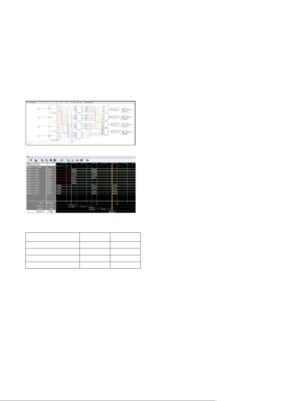
THE EFFECT OF THE DIGIT SLICING ARCHITECTU RE ON THE FFT BUTTERFL Y Yazan Samir, Rozita T eymourzadeh IEEE me mber Department of Elec trical and Electronic, Faculty of Engineering, I nstitut e of Microeng ineering and Nanoelec tronics, Blok Inovasi 2, University Kebangsaan Ma laysia, 43600 B angi, Selangor, Malay sia Email: y azansamir@y ahoo.com , rozita_tey mourzadeh@ya hoo.com ABSTRACT Most co mmunicatio ns systems tend to ach ieve b andwidth, power and cost efficiencies to capa ble to describe modulation scheme. Hence for s ign al modulation orthogon al frequency division multiplexing (OFDM) transceiver is introduced to cover communica tions demand in four generation. However h igh performance Fast Fourier Transforms (FFT) as a main hea rt of OFDM acts beyond the view. In o rder to achieve ca pable FFT, design and realization of its efficient intern al structure is key issues of this research work. In this paper implementation of hig h performa nce butterfly for FFT by applying dig it slicing technique is presented. The proposed design focused o n th e trad e -off between the speed and active silicon area for the chip implementation. The new architecture was investiga ted and simula ted with th e MATLAB software. The Verilog HDL cod e in Xilinx IS E en vironment was derived to describe the FFT Butterfly functionality and was downloaded to Virtex II FPGA board . Keywords --- Digit-Slicing techniqu e; Fast Fourier Transform (FFT); Verilog HDL; Xilinx . 1. INTRODUCTION With the increasing use of transceiver in co mm unication system the usage of and requirement for signal proce ssing has increased. Am ong the digital signal processing block FFT is the most critical p rocessor to transfer one function into another, w hich is called the frequency dom ain representation, o r sim ply the D iscrete Fo urier Transform (DFT) of the original tim e domain. DFT is the main and important procedure in the data analysis , system design and implementation [1]. In order to reduce the complexity computation of the FFT algorithm many m odules have been designed and implem ented in different platf or ms. These modules focus on rad ix ord er or twiddle factor to perform a simply and efficient algorithm which includes the higher radix FFT [2], the mixed-radix FFT [3], the prime-factor FFT [4 ], the recursive FFT [5], low-mem ory reference FFT [6], Multiplier -less based FFT [7, 8, and 9] and app lication-specific integrated circuits (ASIC) system such as [10 ]. ASIC-based system can fit real applicatio n for low- po wer or high per formance; however, it is very solid to modify the function [11] . The study of the digit slicing technique has been dealt by [12, 13, and 14] for the digital filters. The d esign and implementation of Digit slicing FFT has been discussed one time before in [ 15 ]. This paper pro posed the similar id ea with [ 15 ] b y using a different algorithm and different platform which help to improve the p erformance and get higher speed . Recently , FPGAs has b ecome an app licable option to direct hardware solution performance in the real time application. In this p aper, digit slicing ar chitecture was proposed to design the digit -slicing b utterfly . Which is a portion of the computation that combines the results of smaller discrete Fourier transforms into a larger DFT . The FFT butterf ly multiplication is the m ost crucial par t in causing the delay in the computation o f the FFT. I n view of the fact, the twiddle factors in the FFT pr ocessor was know n in advance hence we prop osed to use the digit slicing mu ltiplier to replace with conventional multiplier in FFT butterfly . The paper structure was organized as follow; section 2 describes the FFT ar chitecture in brief, whilst section 3 explains the butterfly conventional architecture . T he digit slicing architecture w ill be discussed in section 4 followed by section 5 that proposes the d esign o f digit slicing butterfly ar chitecture in detail. Finally section 6 and 7 shows implementation result and conclusion respectively. 2. FAST FOURIER TRANSFORM (FFT) A useful m ethod to transform domain from the tim e domain to the frequency domain and the reverse for the implem entation on digital hardware is the discrete Fo urier transform (DFT ). For N -point DFT of a complex data sequence x (n) is defined in equation (1). ) 1 ( 1 ,......., 1 , 0 , ) ( ) ( 1 0 N k W n x k X N n kn N Where x(n) and X(k) are complex numbers, and N j kn N e W / 2 is the twiddle factor. T he DFT of N-point finite sequence represents harmonically related frequency components of x(n) . T he dir ect computation of equation (1) requires the order of N 2 operations where N is the transform size. In 1965, Cooley and Tukey have f ound the new technique to red uce the order o f complexity operations of DFT from N 2 to ( Nlog 2 N ). Consequently , a huge number o f FFT algor ithms have been d eveloped such as Radix-2, radix-4 and split rad ix algor ithm s. These algorithms mostly used for practical applications d ue to their sim ple structure and constant butterfly geometry. In general, higher-radix FFT algorithm h as fewer num bers o f complex multiplications w hereas radix-2 FFT algorithm is the simplest form in all FFT algorithms. Furthermore, it has a regularity that m akes it s uitable for VLSI implem entation as shown in the fallowing equation (2). ) 2 ( ] 1 2 [ ] 2 [ ] [ 1 2 0 2 1 2 0 2 N n nm N m N N n nm N W n x W W n x m X FFT algorithm relies on a divide and conquers methodology, which divides the N coefficient points into smaller blocks in diff erent stages. The first stage computes with groups of two co efficients, yielding N/2 blocks, each computing the addition and subtractio n of the co efficients scaled by the cor responding twiddle factors, called a butterfly for its cr oss-over appearance. These results ar e used to compute the next state of N/4 blocks, which will then combine the results o f two previous blocks, combining 4 coefficients at this point. This process is repeated until we have one main block, with a final computation of all N co efficients [9]. 3. CONVENTIONAL BUTTERFLY ARCHITECTURE The conventional radix-2 DIT butterfly architecture is consisting of co mplex data I/O, complex multiplier and finally complex adder and subtractor Fig. 1. Consider A and B ar e the complex input data, the complex twiddle factor considered as W = Wr – jWi. Finally the complex output are X and Y . T he index r and i represent the real and imaginary par ts resp ectively. ) 4 ( ) 3 ( r N r N W B A Y W B A X ) 6 ( ) ( ) ( ) ( ) ( ) 5 ( ) ( ) ( ) ( ) ( j Bi Br j Wi Wr j Ai Ar jY i Yr j Bi Br j Wi Wr j A i Ar j X i Xr Figure 1. Rad ix-2 DIT FFT Butterfly A rchitecture The implementation of the com plex multiplier required four real multipliers and two real adders Fig. 2. The complex m ultiplier was determined equation ( 11 ). ) 7 ( )] ( ) [( )] ( ) ( ) ( ) ( Wr j Bi j Wi Br Wi Bi Wr Br jW i Wr j Bi Br The real and imaginary parts of the multiplication result is )] ( ) [( Wi Bi Wr Br and )] ( ) [( Wr jB i jWi Br respectively. Figure 2. The Complex Multiplier Structure. The complex adder is required two real adder s to per form addition functionality . ) 8 ( ) ( ) ( ) ( ) ( Bi Ai j Br Ar jB i Br j A i Ar 4. DIGIT SLICING ARCHITECTURE The co ncept behind the digit slicing architecture is any binary num ber can be sliced into a few blocks of shorter binary num bers, w ith each block carrying a different weig ht. In this paper, the fixed- point 2’s com plements arithmetic has been ch osen to represent the input data, wh ich ar e singed numbers with absolute value less than one. The absolute value of the input data x with length of B bits ( x 0 ,x 1 ,x 2 ,….,x B-1 ) has been repre sented in 2’s complemen t as: ) 9 ( 2 1 0 B k j j x x To represent the sliced data, there are many different algorithms . Depend on the data type and word leng th, different structures can b e introduced. In this p aper, the fundam ental sliced algorithm will be presented as followin g: ) 10 ( 2 2 ) 1 ( 1 0 pb b k k pk X x Where x is sliced into b blocks and p is bit widths per block. ) 11 ( 2 1 0 , p j j k j k X X Where X k,j are all either ones or zeros excep t for X k=b-1,j=p-1 wh ich is zero or minus one. This algorithm (6 and 7) applies when the sliced data word length is 2 2 such as 4, 8 , 16, ect. bits. Another algorithm to represent the sliced data with word length 2 2 +1 such as 5 , 9, 1 7, ect. bits can be dealt as following: ) 12 ( 2 1 0 p k k k p X x Br Bi Wr Wi Multipli er Multipli er Multipli er Multipli er Complex Adder Complex Subtractor BrWi+BiWr BrWr-BiWi Ar Ai Br Bi Wi Wr Complex Adder Complex Subtractor Complex Multiplier Yi Xr Xi Yr Delay unit Delay unit Where x is a decimal number whose abso lute value is less than one, and is sliced into b blocks ea ch of p bits wide. The most significant block is k = 0 and this co ntains only the sign bit of x plus leading dummy zeros to make up a block of length p bits [15 ]. on l y or X k 1 0 0 ) 13 ( . 0 1 0 ; 2 1 0 , , k fo r o nly or X X X p j j k j k j k As a comparison betw een the f irst and the second example, the second algorithm required one extra b lock to deal with the sign bit only this mak es the design more complicated and requires more hardw are for the implem entation. In this pap er, the first digit-slicing algorithm has been cho sen to build the digit -slicing FFT butterfly structure. T herefore, any complex numbers, F, can b e sliced into smaller b locks b , each having a shorter word length , p , as illustrated in followin g equ ations: ) 15 ( 2 2 2 2 ) 14 ( ) 1 ( 1 0 ) 1 ( 1 0 pb b k k I pk pb b k k R pk I R F j F F F j F F ) 16 ( 2 2 1 0 , 1 0 , p j j k I j k I p j j k R j k R F F and F F Where F Ik,i and F Rk,I have values wh ich are either zero or one. 5. DIGIT SLICING BUTTERFLY ARCHITECTURE The novel butterfly ar chitecture was designed and investigatin g acco rdingly. In or der to reduce th e co mplexity computation and enhanced the throughput, digit slicing b utterfly obtained by ap plying the digit slicing technique. As mentioned in section 3 the butterfly structure contains of o ne complex multiplier, o ne complex adder and one complex subtractor. The digit slicing architecture has been applied for the butterfly input to slice the data to four groups ea ch carrying f our b its as show n in Fig. 3 . Figure 3. Digit Slicing Structu re The multiplication regarded as the most important operations for most sign al processing systems, but it complex and expensive operatio n. Many techniques have been introduced for red ucing the size and improving the speed of multipliers. Since the tw iddle factor in FFT processor are know n in advanced a special design o f digit slicing multiplier has been proposed to perform the multiplication with the twiddle factor. The digit slicing architecture has been ap plied for the input data and sliced to four groups each has four bits to be multiplied by the constant W = Wr – jWi 16 bits 2’s complement fixed point, which has absolute value less than one to repr esent the FFT twiddle factor. By ap plying eq uation ( 10 and 11 ) to equation (5 and 6) the digit slicing butterfly output will be: ) ( ) ( ) ( ) ( j Bi Br B and j Ai Ar A j Y i Yr Y and jX i Xr X By slicing the input d ata A and B into b blocks each carrying p bits w ide. 1 0 , ) 1 ( 1 0 2 2 2 p j j k j k pb b k k pk A A whe re A A Where A k,j are all either ones or zero s except for A k=b-1,j=p-1 wh ich is zero o r minus o ne. The same for the input B 1 0 , ) 1 ( 1 0 2 2 2 p j j k j k pb b k k pk B B wh ere B B Where B k,j are all either ones or zeros excep t for B k=b-1,j=p-1 wh ich is zero or minus one. The output X has been defined as: 1 0 , ) 1 ( 1 0 2 2 2 p j j k j k pb b k k pk X X w he r e X X Where X k,j are all either ones or zeros excep t for X k=b-1,j=p-1 wh ich is zero o r minus o ne. Putting all the slicing equations above into equation (3) ) 17 ( 2 2 2 2 2 2 ) 1 ( 1 0 ) 1 ( 1 0 ) 1 ( 1 0 r N k k k r N pb b k k pk pb b k k pk pb b k k pk r N W B A X W B A X W B A X r N k ik r N k k rk ik rk k k W B X of part ag and W B A X of part al jX X X nu mber c ompl ex is X Im Re Same step for output X has been applied to get output Y r N pb b k k pk pb b k k pk pb b k k pk W B A Y ) 1 ( 1 0 ) 1 ( 1 0 ) 1 ( 1 0 2 2 2 2 2 2 ) 18 ( r N k k k W B A Y r N k ik r N k k rk ik rk k k W B Y of part ag and W B A Y of part al jY Y Y n umbe r c ompl ex is Y Im Re Finally , the complex output has been represented as followin g: ) 20 ( ) 19 ( Wi B Wr B A X Wi B Wr B A X rk ik ik ik ik rk rk rk ) 22 ( ) 21 ( Wi B Wr B A Y Wi B Wr B A Y rk ik ik ik ik rk rk rk The co nstant tw idd le factor was stored in look -up tab le ROM. 6. IMPLEM ENTATION RESULT Two different modules have bee n implem ented for radix- 2 DIT butterfly. The first module uses the conventional architecture for the butterfly where the twiddle factors are stored in ROM and ca lled by the butterfly to b e multiplied with the inputs using the dedicated high speed m ultiplier equipped with the Virtex-II FPGA and the other module uses the digit slicing m ultiplier -less architecture to A 16 bits Digit Slicing Unit 16 to 4 b its 4 bits A2 4 bits 4 bits 4 bits The in put Data for the butterfly 16 bits A3 A3 A2 perform the multiplication with the twiddle factor. Both modules has been built and tested in MATLAB Fig. 4 , then cod ed in Ver ilog and synthesized using the XST - Xilinx Synth esis Technology tool. The target FP GA w as Xilinx Virtex-II XC2V50 0-6-FG456 FPGA [1 7 ]. ModelSim simu lation result of digit slicing rad ix-2 DIT butterfly is shown in Fig. 5, while the synthesis results for the two m od els are p resented in T able 1, which demonstrates the hardware specificatio ns for the design. It show s the maxim um throughput of 535.9 0 MHz for the mention ed system . As well as the digit slicing multiplier has performed the m aximum throughput of 609 MHz. Figure 4. MAT LAB design of Digit Slicing Butterfly Figure 5. Simulation result of digit slicing Butterf ly TA BLE 1. HARDW ARE SPECI FI CATI ONS OF T HE DIG IT-S LI CING BUTTERF LY Xilinx Virtax- II FPGA XC 2v250-6F G456 Total equivale nt gate Maximum Fre qu ency MHz Conventional butterfly 18,408 198.98 7 Digit-Slicing Butterfly 31,15 9 535.90 Conventional 16 bits M ultiplier 4,131 220.16 Digit-Slicing 16 bit s Multiplier 6,483 609.60 7. CONCLUSION This p aper presented design and implementation of digit slicing butterfly for FFT stru cture. The implementation has been coded in Verilog hard ware descriptive language and was tested o n Xilinx Virtex-I1 XC2V500 -6- FG456 prototyping FPGA boar d. A maxim um clock frequency of 535.90 MHz has been o btained from the synthesis report for the digit slicing butterfly . REFERENCES [1] A. V. Oppenheim and C. M. Rader, “ Discrete-Time Signal Processing, 2nd ed. ” Upper Saddle River, NJ:Prentice-Hall 0137549202, (1990). [2] G. D. Bergland, “A radix -eight fast-Fourier transform subroutin e for real- valued series,” IEEE Trans. Audio Electroacoust , vol. AE-17 , no. 2 , pp.13 8 -144, Jun e 1969. [3] R. C. Singleton, “An algorithm for computing th e mixed radix fast Fourier transform,” IEEE Tra ns. Audio Electroacoust , vol. AE-17, no. 2, pp.9 3-1 03, Jun e 1969. [4] D. P . Kolba and T. W. Parks, “A prime factor FFT algorithm using h igh-speed co n volutio n,” IEE E Trans Acou st. Speech, Sign al Process , vol. ASSP -25, no. 4, p p.281 -29 4, August 1977. [5] A. R. Varkonyi- Koczy, “A recursive fast Fourier transform algorith m,” IEEE T rans Circuits Syst em II , vol. 42, no. 9, p p.614 -616 , September 1995. [6] Y. Wang, Y. Tang, Y. Jiang, J. G. Chung, S. S. Song and M. S. Lim, “Nov el mem ory reference reduction methods for FFT implementation on DSP processors,” IEEE Trans Sign al Processing , vol. 55 , no. 5 , pp.23 38 -234 9, May 2007. [7] Y. Zhou, J. M. Noras and S. J. Shephend, “Nov el design of multiplier- less FFT p rocessors,” sign al processing , vol.87 , Issue 6, pp. 1 402 - 1407, June 200 7. [8] P rasanthi.R, Anuradha. V , S.K. Sahoo, Chand ra Shchar, "Multiplier less FFT Pro cessor Architecture for Signal and Imag e P rocessing", ICISIP , 20 05. [9] Ma hmud Benhamid & Masuri Othman “FPGA Implem entatio n of a Canonical Signed Digit M ultiplier -less based FFT Processor for Wireless Communication Applications” ICSE20 06 Proc ., Kuala Lumpur, Malaysia , 2006. [ 10 ] B. M. Baas, “A low -power, high-performance, 1024 -point FFT processor,” IEEE J. S olid-S tate Circuits , vol. 34, no. 3 , pp.380 -387, March 1999. [ 11 ] Yi -P in Hsu and Shin -Yu Lin," Parallel-computing approach f or FFT impleme ntatio n on digital signal processor (DSP)", World Academy of Science, Engineering and Technology 42, 2008 . [ 12 ] Bin Nun M. A. and Wood ward M. E.: “A Mod ular Approach to the Hardware Implem entatio n of Digital Filters” The Radio and Electronic En gineer , vol.46, no.8/9 , LONDON, September 1976 [ 13 ] P eled A. & Liu B. “ Digital sig nal p rocessing theory, design, an d implementa tion. ” USA: John Wiley & Sons., 1976 [ 14 ] Sharrif Z. A. M. “Digit slicing architecture for real time digital filters”. PhD thesis. Loug hborou gh University.UK , 1980 . [ 15 ] S. A Sama d , A. Ragoub, M. Othman & Z. A. M. sheriff “Implem entation of a High Speed Fas t Fourier Transform VLSI Chip” Microelectronics journa l , UK, 1998. [ 16 ] J. W. Co oley, J. W. Tukey , "An A lgorith m for the Machine Calculation of Complex Fourier Series," Math , Comp, Vol.19 , pp.2 97-3 01, April 196 5. [ 17 ] Xilin x, Inc. http // www .xlinx.com/virtex2
Original Paper
Loading high-quality paper...
Comments & Academic Discussion
Loading comments...
Leave a Comment