Advanced Frequency Identification Power Metering System for Energy Usage
Energy meter measures the amount of power consumed by electrical loads in residential, industrial and commercial applications. In this project, the focus goes to the implementation of a smart power measurement system to allocate identification for in…
Authors: Rozita Teymourzadeh, Ahmed JA Abueida, Kok Wai Chan
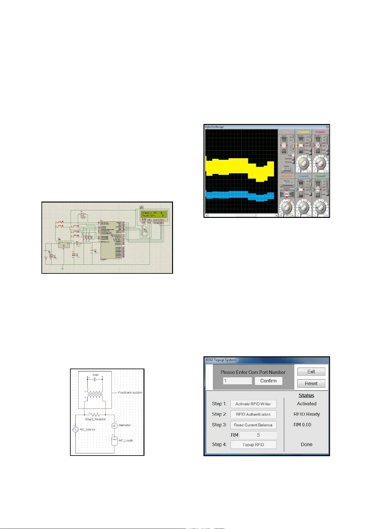
Advanced Frequency Iden tifi cation Power M ete ring Sys tem for Energy Usage Rozita Teymo urzadeh, Ahmed J.A. Abueida, Kok Wa i Chan, Mahmud Iw an S, Vee Hoong Mok Facult y of Engin eering, Technolo gy & Built Environ ment UCSI Univers ity Kuala Lumpur, Malaysia rozita@u csiuniversit y .edu.m y Abstract —Energy meter measures the amou nt of power consumed by electrical loads in residential, in dustrial and commercial applications. In this project, the focus goes to the implementation of a s mart power measurement sy stem to allocate identification f or individuals and determine the client’s energy usage. The incorporat ion of two PIC 16F87 7A microcontrollers and radio-frequency identifica ti on (RFID) reader in t his research wo rk m ake the system opera tion smooth and reliable. T his paper pres ents the development o f an intelligent p repaid power m etering s ystem e nabling pow er utilities to collect electricity bills from consumers prior to the usage of power. Home ow ners are able to monito r reliable power consumption data for efficient power management. To conclude, a graphical us er interface (GUI) has b een designed to b e applied for data t r ansmission b et ween the p ersonal computer and RFID smart card which allows the credit to be transf erre d to the smart card. Index Terms —Prepaid pow er m eter ; G lobal System for M ob ile Communication (GSM) network; Short Message Service (SMS); Radio-frequency identification (RFID); PIC microcontroller I. I NTRODUC TION Recent hikes in home energy costs across many c ountries has led t o the increase i n global energy awareness a mong home o wn ers. The smart prepay ment metering system becomes the economical subst itution to the conven tional electrome chanical mete rs for effic ient u tilization of energ y. While enabling h ome ow ners to co nstantly monitor energ y consumptio n data at a desire d time interval, the prepaid powe r metering system facilita tes a flexible and accurate billing scheme for electri cal power usages. Alo ng with the i ntegration of an intelligent home automation system [1-2], home owners can adjust their electricity consumption behavior by o pting to switch off se lected applia nces remotely during peak p eriod s. The smart prepaid electricity metering s y stem i s capable to detect and deter power theft issues which inc lude tampering and modify ing of con v entional elec tromechanica l meters resulting in lower readi ng on the m eter. In view of the gr owth in globa l en ergy dem and , re search and deve lopment in th e electric al fie ld today has been concentrated on the developme nt of innova tive metering techno lo g ies. Research work ha s been conducted i n [3] utiliz ing Microso ft Visual Basic 6 .0 in devel oping a user int er face program t o issue smart card ID and increase the credit in the custome rs’ card used for the p re paid electricity me ter ing system. ZigBee and GPRS t echnolog ies have been propose d in [ 4] for the design o f the wireless remote househo ld metering system. Dang et al. [5] exp lored the impleme ntation of the power met ering automatic s y stem, while addre ssing the complexi t y of the GPRS/CDMA communicatio n channel to ensure data exchange sec urity and stability of prepaid functio ns. RFID has been integrated into the power meter and outage recording system in [ 6]. M. W asi- ur-Rahman et al. in [7] proposed a SMS based remote metering system that utilize s G SM n etw orks amongst many o ther research works [8-11]. Survey results fro m a user study about the implement ation of a digital feedback sy stem along with a prepaid ele ctricity metering system in a Chinese universit y dormitory in Ch ina have been collec ted and recently published [12]. II. D ESCRIPTI ON Top-up circuitry bas ed p acka ge pla y s a significant role i n the frequency id ent ification system in this project . The top-up circu itry con sists of DC power s upply, r egu lator, RFID writer /reader module, and serial port. In proposed design, the operatio n management of the circuitry s ystem t akes plac e interna lly. In the operatio n of the RFID t op-up s y stem, the RFID re ad er first d etects the RFID card signal and determine the validity of t he card. The top-up operat ion can be achieve d by the interfacing between the top-up circuitry and user persona l computer (PC ) vi a USB RS232 using the graphi cal user inte rface (GUI) window. The RFID reader/ writer m odule operat es at TTL l ogic level whereas t he s erial commu nication i n PC works on RS232 standard (±25V). Since th e RS232 serial communic ation in a com puter is n ot compatible with the RFID reade r/writer mod ule, MAX232 is utilized to enabl e the duplex communi cation b etween t hem by co nvertin g TTL logic levels to RS232 logic levels. T he so urce of th e power for t he RFID to p-up circuitr y is from the DC p ower supply. The DC power supply will supply 7V to 15V DC to the RFID top-up circuitr y . T he regul ator i n the RFID top-up circuitry converts the inpu t DC volt age to + 5V. T his outp ut voltage will be u sed as the power supply for MAX 232 and th e RFID reader/wri ter devi ce. Fi g. 1 shows t he fun damental sy stem operation o f the RFID based top -up circuitr y at a glance. Figure 1. R FID top-up circuitry. The RFID top-up circuitry i s incorpo rated in the proposed inte lli gen t prepa id powe r metering s ys tem, as il lus trated in Fig. 2. Two 8 -bit PIC16F877A microcontrol lers have been chosen to be int eg rated with the prepaid electricity metering system for hi gh eff iciency u sage. The program stored inside the microcont roller contains the p rot ocol for acce ssing various hardware p er ipherals such as LCD, relay, G SM module, and etc. The microco ntroller is essentia l in determining the credit balance from the communicati on between the RFID card and RFID reader, triggering the relay to turn O N the lo ads, and display ing the credit b alanc e along with consumed power i n the LCD display. Another P IC microcont roller is embe dded in the p rot otype of t he proposed RFID prepaid po w er meter which is resp onsible to send 5V to trigger the GSM modem in sending Short M es sage Sy stem ( SMS) text messages as well as produce aler t sound from the buzzer when the cre dit is low. The text m essages sent to mobile p hones contain f eedb ack status indicating lo w credit for the prepaid power meter . Failing to transfer credit s into the RFID card b y consumers upon the credit reaching zero will lead to relay s cutting off t he supply of electrici t y . Once the home owners have increase d credits in t he RFID card using the developed cred it top-up graphical user interface, the relay connects home automation and re sumes the elec trical su pply. Figure 2. Pro totype of the propos ed RFID prepaid power m eter. III. S TAGE R EALIZATION AND S IMULATI ON The RFID prepaid power metering al go rithm is s hown in Fig. 3. The progra m starts executing with the config uration of two I/O ports for the purpose of reading and writing data. The I/O inc ludes the RFID rea der connectio n to the microco ntroller a nd LCD display . Figure 3. RFID prepaid metering algorithm flowchart. Once both the I/O por ts and the direction of data flow have been determined, the RFID card is read from the RFID reader . The RFID reader t rans mits an encoded radio signal to interroga te an d valida te t he card. With the validated RFID card, the PIC microcontroller then com putes the c redit deduction and displays b oth power usage and credit. Due to the uniquenes s of t he RFID s mart card, the credits will not be transfer red to the card if a diff erent RFID card is used. The algorith m is then restarted when the power is turned off. Fig. 4 demonstrates the simulation of the proposed RFID based prepaid power meteri ng system being implemented using P rote us. A 16x2 character LCD is used to display t he remaining credit and total power consumed i n this proposed prepaid power meter for the ease of monitoring by home owners. Both RFID reader/write r module and RFI D card are not simulated with the proposed RFID based prepaid power metering system. Hence, the value of credit bala nce and consumed power display ed on the LCD display during simulation are respe ctively zero. Figure 4. Sim ulation of the p r oposed RFI D based prepaid m etering system. A feedback path is connected at the load as a curren t sensing circuit using r es isti v e shunt. Commonly applied in the RFID power meter, the resis tive shunt is simply a resistor placed in s er ies with the load. A voltage is de ve loped across the shunt th at is directly proportional to the current flowing through t he load. A capacitor connecte d to the o utpu t of the step-d own transformer conver ts the alternating current (A C ) voltage to the direct curren t (DC) voltage as illustrated i n Fig . 5. Amme ter connected in the ci rc uit is used for the purpose of calibrat ion to observe the output V out in relation to the cur rent when ca librated us ing differen t AC load s . Figure 5. C urren t s ensing feedback path. The waveform simulat ion result of the top-up circuitry using Pro t eus software is illust rated in Fig. 6. A series of puls e generator has b een used as an alternative to the RFID writer during simulation to t est the op erati on o f the circuit. The simulate d waveform resembles an amplitude-shi ft keying (ASK) signal. The digital signal modulate s on the c arri er generate d by MAX232. The amplitude of the c arrie r changes with respe ct to the amp litude of t he dig ital signal. He nce, under magn ification, the ASK sig nal is a sinusoidal wave form. Figure 6. ASK signal generated during simulation of RFID top- up circu it r y . The RFID top-up system is a GUI program devel oped for the user to increase the credit i nsid e the valid ated consumer smart card for the prepay me nt power metering system as shown in Fig. 7 . Microsoft Visual Basic 2008 is used as the tool to write the programs for c ommunication between the persona l computer and the smart card. COM port 1 has been utilized for the RF ID credit to p-up program . In the graphical us er interfac e, it displays the buttons for the user to step-by -step select the actions r eq uired to in cre ase the credits on the RFID card. The top-up steps include RFID writer activat ion, RFID card authentication , reading of the curren t cred it balance on the RFID card, and RFID credit top- up. The current status of the cred it top-up process is displaye d on th e GUI termina l. The RFID interface allows the meas ured power consumpti on data to be stored temporari l y i n the RFID smart card and transferred t o the credit top-up graphica l user interface . Figure 7. Test run on proposed RFID based prepaid metering system. With t he RFID s mar t card authenticated, an amount o f credit can then be loaded by the user onto the smart card. User is notified about the success of t he credit t op-up process. The remaining credits inside the smart card after being increase d will then be shown on the 16x2 character LCD. Fig. 8 shows that the remaini ng credit balance on the sm ar t card is RM 5 upon t he successful credit top- up proces s. Figure 8. C r edit top-up for RFID prepaid m eter. IV. R ESULTS A ND D ISCUSSI ONS Table 1. Experimenta l power c onsu mption t est on RFID power meter under diffe rent ligh t bulbs. Time (s) Power Consumpt ion (in Wat ts) Light bul b 1 L ight bu lb 2 Light bulb 3 5 57 24 14 10 57 24 14 15 57 24 14 20 57 24 14 25 57 24 14 30 57 24 14 35 0 24 14 40 0 24 14 45 0 0 14 50 0 0 0 55 0 0 0 60 0 0 0 Experiment t est s were conducted on the operations of the RFID power metering s y stem using dif feren t li ght bulbs and the results were t abled in Table 1. From the experime ntal test results, it is seen that within 1 minute, the light bulb rat ed 60 Watts has turned off. This is due t o the higher power consumpti on b y the 60W light bulb as compared to the power consumpti on b y 25W and 1 5W light bulbs re spectively . From this experiment test, i t can be deduced that higher power consumpti on will l ead to faster credit deduction from the power mete r. Figure 9. D eduction of credits fo r RFID prepaid meter. The experiment was cond ucted on the proposed power metering sy stem with the cr edit balance i n Fig. 9. As the remaining credit c ontinues t o be deducted, total power consumpti on by electrical loads is displayed from the LCD display fo r the ease of energy monitori ng whilst the remaining credit drops to RM 1 (Fig. 10). The PIC microcontrol ler then sends 5V to trigger the GSM modem which then s end s t ex t message s to home o wner s indicating that t he credit for the power meter system is runni ng low (Fig. 11). The delay of receiv ing the text message, as had been tested p ractic ally [ 1], does not exceed 2 or 3 s econ ds due to GSM communicatio n that i s mostly governed by the SMS protocol. Concurre ntly, the alert sound f rom the buzzer will als o be trigge red to ensure that the user s are aware t hat the elect rical power w ill be cut of f if cre dit has yet to be increa sed. Figure 10. Power metering syst e m behavi our during low credit . Figure 11. SMS notification o f low cre dit f or RFID prepaid met er. V. C ONCLUSION A RFID b ased po w er metering system which includes the credit top-up circuitry has been designed and implemented. The proposed power metering system enables consumers to monitor power consumption data at a d esi red time interval. With accurat e power consump tion data, home owners will be able to gain co ntrol on daily home energy usage. Experi mental tests conducte d on the power metering system has shown that the developed graphical user i nter face ensure s consumers pay for their utility bill in a timely m anner to prevent the electric ity bi ll to prevent the electri cal supply from being cut. With the security uniqueness o f the RFID card, this proposed advanced frequency power metering s y stem will be able to deter powe r theft issu es. R EFERENCES [1] R. Teymourzadeh, S. A. Ahmed, C. Kok Wai, and H. Mok Vee, "Smart GSM bas ed Home Automation System," in Proc. 2013 IEEE Confe rence on Systems, Proces s & Control ( ICSPC ) , Kuala Lumpur, Malaysia, pp. 306-309. [2] S. Ah m ad , “Smar t mete rin g and home auto m ation solutions for the next decade,” in Proc. 2011 International Con ference on Emerging Trends in Networks and Computer Communications (ETNCC) , Udaipur, pp. 200-204. [3] B. H. Kwan and M. Moghavvemi, “PIC bas ed s mart card prepayment system,” i n Proc. 2 002 Student Conference on Research an d Development (SCOReD 2 002) , Shah Alam, Malaysia, pp. 440-443. [4] Q. –x. Li and G. Li, “Design of remote automatic meter reading system b ased on Z igBee and GPRS,” in Proc. of the Third International Symposium on Computer S cience and Computational Technology (ISCSCT ’10) , J iaozuo, Chin a, pp. 186-189. [5] S. –l. Dan g, J . –f. Yang, F . –s. Wei, a nd H. – k. Que, “Design of prepayment implementation and i ts data exchange s ec urity protection based on Power Met e ring Au tomatic system,” in Proc. 2 012 IEEE International Conf erence on Co mpute r Science an d Automation Engineering (CSAE) , Zhangjiaj ie, p p. 331-335. [6] C. Shu n-Yu, L. Sh ang -W en, T. Jen-Hao, and T. Ming-Chang, "Design and i m ple me ntati on of a RFID-based power meter and outage r ecording system," in Proc. 200 8 IEEE International Conference on Su stainable Energy Technologies (ICSET 20 08) , Singapore, pp. 750-754. [7] M. Wasi-ur-Rahman, M. T. Rahman, T . H . Khan, and S. M. L . Kabir, “ Desig n of an intelligent SMS based remote met ering system,” in Proc. 20 09 International Conference on Information and Automation (ICIA’09) , Zhuhai, Macau, pp. 1040-1043. [8] G. Bo, L . Xinyu, a nd X . Junming, "Th e Design and Realization of A cquisition Equipment in Remote Reading System Base on Low Voltage P ower Li ne Carrier," in Proc. 2010 Int ernational Symposium on Co mputational Intelligence and Design (ISCID) , Hangzhou, pp. 24-27. [9] K. Li , J. Liu, C. Yue, and M . Zhang, “R emo t e p ower management and meter-reading sys tem bas e d on ARM microprocessor,” in P roc. 2 008 Conference on Precision Electromagnetic Measurements Dig est (CPEM 2008) , Broomfield, Colorado, pp. 216-217. [10] Z. –h. Zheng, X . –j . Z hou, and W. Zhang, "Design and Implementation of Remote M e ter Reading System," in Proc. 2010 2 nd International Conference on Software Technology and Engineering (ICSTE) , San Juan, Pu er to Ri co, Volu me 2, pp. 247-250. [11] Q. Zongming, Y. Xiaoshan, and S. Zhenhai, “Database d es ign of GP RS-oriented re mo te met er reading system,” in Proc. of 2011 International Conference o n Co m puta tional P roblem- Solving (ICCP) , Chengdu, China, pp. 493-495. [12] T. Li u, X. Ding, S. Lindtner, T . Lu, an d N. Gu, “ The Collective Infrastructural Work o f Electricity: Expl oring Feedback in a Prepaid University Dorm in Chi na,” i n Proc. 2013 ACM International Joint Conference on Pervasive a nd Ubiquitous Computing (UbiComp’13) , Zurich, Switzerland, pp. 295-304.
Original Paper
Loading high-quality paper...
Comments & Academic Discussion
Loading comments...
Leave a Comment