An Improved Recursive and Non-recursive Comb filter for DSP applications
The recursive and non-recursive comb filters are commonly used as decimators for the sigma-delta modulators. This paper presents the analysis and design of low power and high-speed comb filters. The comparison is made between the recursive and the no…
Authors: Rozita Teymourzadeh, Masuri Othman
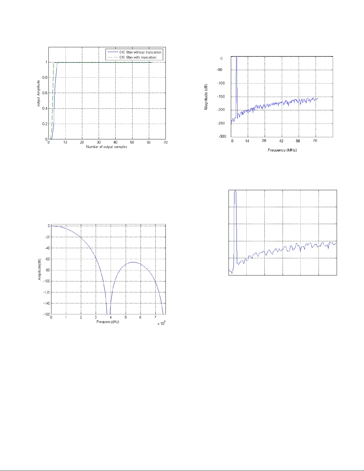
An Impr oved Rec ursive and Non-r ecursive Comb Filter for DSP Applications Rozita Teymourz adeh and Masuri Othman Departm ent of Electrical, E lectronic and System s Engineering VLSI Desig n Research Group National Univers it y of Ma laysia rozita60@v lsi .eng.ukm .my Abstract The recursive and non -recursive co mb filters are co mmonly used as decimators for the sigma delta modulators. This paper presents the analysis and design of low po wer and high speed comb filter s. The comparison is made betwee n the recursive and the non -recursive comb filters w ith the focus o n high speed and sa ving power cons umption . Desi gn procedures and examples are g i ven b y using Matlab and Verilog HDL f or both recursive and non -recursive comb filter with emphasis on fr equency response, trans fer function and register width. The implementation result s show that non-recursi ve comb filter has capabilit y of speeding up the circuit and reducing p ower co mpared to recursive one w hen the decimation ratio and filter order are high. Us ing Modified Carry Look -ahead Adder for summation and also appl y pip elined filter struc ture ma kes it more compatible for DSP ap plication. 1 Introduction lectronic and communicati on system for speech processing a nd radar make use o f s igma d elta modulator in t heir operation [1], [2] . Future system are required to operate with lo w power and high speed and therefore the sigma delta m od ulator must be designed accordingly. The comb filter that will be d esigned in this paper is part of the sigma delta modulato r which is required to be low power and high speed perfor mance. Co mb filter was applied to decimate t he sampling frequency from high to low and obtain hig h resolution . It is also used to perform filtering of the out of band quantization noise and prevent excess aliasing introduced d uring sampling rate decreasing. Comb filter is pop ular because of no multipliers and coefficient storages are requir ed due to all filter co efficients are unity [4]. Hence lo w po wer and high sp eed will be key i ssues i n chip implementation of co mb decimators. There ar e two type of co mb filter, first is rec ursive co mb filter and second is non-recursive co mb filter. In 1981, Eugene Ho genauer [3] invented a new class of economical digital filter for dec imation ca lled a Cascad ed Integrator Comb filter (CIC) o r recursive co mb filter. This f ilter con sists o f t hree pa rts which are Integrator , co mb and down sampler. CIC filter is considered as recursive filter because of the feedback lo op in integrator cir cuit. The seco nd type called non-recursi ve co mb filter which has regular structure and this property makes it s uitable for VLSI implementation. In 19 99, Yonghon g Gao, Lihong Jia and Hannu T enhunen [9] introduced this f ilter bec ause of its advantages such as no rec ursive loop and using l o w po wer consumption due to computations are per formed at lo wer sampling rate. The next section d escribes the mathematical formulation and block diagram o f CIC filters in detail. Sec tion 3 discusses non-rec ursive comb filter al gorithms and it s advantages co mpared to recursive filter. Enhanced high speed architecture is d epicted in section 4. Section 5 shows implementation and design result in brief. Finally conclusion is expressed in sectio n 6. 2 Recursive CIC filter de sign Recursive comb filter or CIC filter consist of N sta ges of integrator and comb filter which ar e connected b y a do wn sampler stage as sho wn in figure 1 in z domain . The CIC filter has t he following transfer function: (1) where N is t he number of stage, M is the differential delay and R is the deci mation factor. E 1 0 1 ) ( ) 1 ( ) 1 ( ) ( ). ( ) ( RM k N k N N RM N C N I z z z z H z H z H In this pap er, N, M and R have b een chosen to be 5, 1 and 16 respectively to avoid overflo w in each stages. Figure 1: One-stage of CIC filter block diagra m N, M and R are parameters to deter mine the register length requirements necessar y to assure no data loss. Equatio n (1) can be express as follo w: From the eq uation, the maximum re gister growth/ width, m ax G can be expressed as: N RM G m ax (3) In other word, m ax G is the maximum register gro wth and a function of the maximum o utput magnitude due to the worst possible input conditions [ 3 ]. If the input data wor d length is in B , most significant bit (MSB) at the filter o utput, m ax B is given by: ] 1 l o g [ 2 m ax in B R N B (4) In o rder to reduce the data loss, nor mally t he first stage of the CIC filter ha s maximum number of bit co mpare d to the other stages. The recursive part of the CIC filter has to operate with the high oversampl ing rate and has large width length which is t he cau se of high po wer consu mption. Due to recursive loop in its struct ure, low power is limited b y the high range of calcula tion in t he integrator s tage. Since the integrator stage works at the highest oversa mpling rate with a large internal word length, decimation ratio a nd f ilter order increase which result i n more po wer co nsumption a nd speed limitation. I n thi s case , a n on -recursive filter is proposed to replace wh e n the decimation ratio and filter order are high . 2.1 Truncation for speeding up purpose Truncation means estimating and removing Least Significant Bit ( LSB) to reduce t he area req uirements o n chip and po wer cons umption and also increase speed of calculation. Although this estimation and removing introduces additional error, t he error can be made small enough to be acceptab le for DSP app lications. Figure 2 illustrates five stages of the CIC filter when m ax B is 25 bit so truncation is ap plied to reduce register width. Matlab software helps to find word length in integrator and comb section . 1 Z + + + - Integrator 1 25 bit 1 Z + + Integrator 2 22 bit R 1 Z + + Integrator 3 20 bit 1 Z + + Integrator 4 18 bit 1 Z + + Integrator 5 16 bit 16 1 Z Comb 1 16 bit + - 1 Z Comb 2 16 bit + - 1 Z Comb 3 16 bit + - 1 Z Comb 4 16 bit + - 1 Z Comb 5 16 bit a_in s_out Figure 2: Five-stag e of truncated CIC filter include integrator and comb cell 3 Non-Recursive Co mb filter design The non-recursive co mb filte r [ 6] , [ 7] has ab ility o f wide range o f rate cha nge. Its tr ansfer function is shown as follow: N M i N i i N R i i i M z z z z H 1 0 2 1 2 0 1 0 1 ) ( (5) where R is the deci mation facto r, N is the filter order and M is the number of stage . Note that R should be a power of 2. Non-recursive co mb filter structure is shown in Figure 3. Compared to the CIC filter structure , 1) it is clear that during d ecimation proc ess and decr easing sa mpling frequency, t he number of bit i ncreases a nd it is the cau se of the sa ving i n power . 2 ) The com b deci mator using the non - recursive algorithm can achie ve higher speed since the first stage always has small word length and also 3 ) whe n decimation ratio increases, the silicon size of the recursive design algorithm increases s lowly compared to the non - recursive design a lgorithm and it i s next ad vantages of using non-recursi ve filter as deci mator. Non-recursive co mb filter was i mplemented and R, M and N are selected re spectively to be 8, 3 and 5 so i f input word length is considered to be 5 output words length change to 20. Every stage is included of N blocks non -recursive comb filter (See Figure 5). N N RM k N RM k k N RM k k N RM k k N RM k k RM z z z z k h z H 1 0 1 0 1 0 1 0 ) 1 ( 0 1 ) ( ) ( Input Sample rate 1 1 1 z R RM z 1 Integr at or Decimator Comb Output Sample rate R F s s F (2) Figure 3: Non-recursive Co mb decimation filte r 4 Speed improve ment 4.1 Pipeline structure One way to ha ve high sp eed comb filter is by i mplementing the pipeline filter struct ure. Figure 4 shows pipeline CIC f ilter str ucture whe n tr uncation is also app lied. In the pipelined structure, no additional pipeline registers are used. So t hat hard ware requirement is the sa me as in the non -pipeline [8 ]. CIC deci mation filter clock rate is d etermined b y t he first integrator stage th a t causes m or e propagation delay than any other stage due to m a ximum number of bit. So it is possible to use a higher clock rate for a CIC decimation filter i f a p ipeline struct ure is used in t he i ntegrator stages, as compared to non -pipelined integrato r stages. Clock rate in in tegrator section is R times h igher than in the comb sectio n, so pip eline structure can not app lied for comb section. Non- recursive co mb filter has no integrator p art; therefore pipeline structure is used for c omb stages. Figure 5 shows Pipe line non- recursive comb filter. It is achieved by locating register after MCLA in stage M . Figure 4: Five-stag e of truncated pipeline CIC filter include integrat or and co mb cell Figure 5: Pi pelined structure of sta ge M in non-recursive Comb filter 4.2 Modified Carr y look-ahea d Adder (MCLA) The other tech nique to i ncrease speed is u sin g Modified Carry Look-ahead Adder. MCLA was selected to perform the su mmation in both recursive and n on - recursi ve co mb filters. This im pro ve in speed is due to the carr y ca lculation in MCLA. In the rip ple carry ad der, m ost si gnificant bit addition has to wait for the ca rry to ripple through from the least signi ficant bit ad dition . T herefore the carry o f MC LA adder has b ecome a focus o f study in speeding up the adder circuits [5 ]. The 8 b it MCLA structure is sho wn in F igure 6 . Its block diagram consists of 2, 4-bit module which is connected and each previous 4 bit calculates carry out for the next carry. The CIC filter i n this paper has five M CLA in integrator parts. T he maximum nu mber of b it is 25 and it is decreased in next stages. So it tr uncated respectively to 25, 22, 20, 18 and 16 bit in each add er, left to right. Non-recursive co mb filter has fifteen MCLA i n non - recursive part. The Verilog code has b een written to i mplement summation. T he M CLA Verilog co de was do wnloaded to the X ilinx FPGA chip. It was found minimum clock perio d on FPGA board is 4.389ns (Maxi mum Frequenc y is 220 MHz). Figure 6: The 8 bit M CLA structure 5 Design Results Figure 7 shows the amplitude of the CI C filter o utput ver sus output samples number, before and after tr uncation is applied for the filter. As see n in Figure 7, o utput amplitude curve of the filter is sharper when it is trunca ted an d some LSB is discarded compared to filter response witho ut truncation . It s hows increasing the speed of filter calculation after tru ncation. When N = 3 Block 1 Block 3 Block 2 N z 1 1 1 Z 1 Z 1 Z 1 Z 1 Z 1 Z + + + a0 b0 p0 g0 a1 b1 p1 g1 a2 b2 p2 c1 c2 a3 b3 p3 g3 CLL-1 c3 a5 b5 p5 g5 a6 b6 p6 g6 c6 a7 b7 p7 g7 c7 a4 b4 p4 g4 c4 c5 CLL-2 c8 c4 s0 s1 s2 g2 s3 PFA PFA PFA s5 s6 s7 s4 PFA PFA PFA PFA ) ( n y N z 1 1 N z 1 1 N z 1 1 ) ( n x i s f 2 / 1 2 / i s f 2 2 2 Stage 1 Stage M Stage 2 C+MN bi t C bit C+2N bit C+N bit 1 Z R 1 Z 1 Z 1 Z 1 Z 1 Z 1 Z 1 Z 1 Z 1 Z + + + - + + + + + + + + + - + - + - + - 25 bit 22 bit 20 bit 18 bit 16 bit 16 in Comb 1 16 bit Comb 2 16 bit Comb 3 16 bit Comb 4 16 bit Comb 5 16 bit out Integrator 1 Integrator 2 Integrator 3 Integrator 4 Integrator 5 Figure 7: Truncation effect on CIC filter am plitude vs. o utput sa mple number Figure 8 illustrate t he frequency response o f the co mb filter when the sa mpling frequency i s 6.144 MHz and the pass band frequency is 348 KHz . Figure 8: Comb filter frequency response for R =16, M =1 and N =5 Figure 9 shows t he meas ured baseb and output spectra before (see Figure 9 (a)) and after ( see Figure 9 (b)) the decimation functions . The recursive and non-recursive comb filter Verilog co de was wrote and si mulated by Matlab soft ware. It is fou nd Signal to No ise ratio (SNR) is 141.56 dB in sigma delta modulator output and SN R is increased to 145 .35 dB in the decimation comb stage. To improve the signal to noise ratio, word length of recursive and non-recursive c omb filter should be increased but the speed of filter calcu lation is also decrea sed . (a) (b) Figure 9: Signal spectra ( a) Output sigma delta m odulator SNR (b) Output Co mb filter SNR Clock frequency versus deci mation factor is shown in Figure 10 when highest clock frequency i s 90 MHz . As seen in the figure , recursive comb f ilter (CIC) c urve decreases wh en d ecimation factor is i ncreased. According to equation (4) , CIC filter word length which has an inverse effect on clock frequency has relation with deci mation factor. so increasing d ecimation factor is the cause of clock frequency li mitation. whereas, wo rd le ngth o f non rec ursive comb filter is not depend o n deci mation factor an d increasing deci mation facto r do se not change clock frequency and its value i s constant. - 250 - 200 - 150 - 100 - 50 0 1 2 3 4 5 0 Frequency (MHz) Magnitude (dB) (a) (b) Figure 10 : Working frequency co mparisons of the (a) recursive and (b) non- recur sive comb filter 6 Conclusions Recursive a nd non-recursiv e comb filter s have been designed and investi gated. Enhanced high Speed recursive and no n-recursive co mb filters was sho wn b y using p ipeline structure a nd replacing with the modified carry look-ahead ad der (M CLA). The evaluation indicates non -recursive comb filter is attractive co mpared to the recursi ve one due to lo wer po wer consumption a nd higher speed. First stage of recursive comb filter (CIC) w ord length always has maximum bit number a nd it is dec reased b y tr uncation function whereas first sta ge of non-recursive filter has minimum word length size co mpared to o ther stages, so it is the cause of achie ving higher speed. However Recursi ve co mb filter (CIC) is attractive when t he decimation ratio and filte r order are not high . References [1] R.E.Crochiere and L.R. Rabiner , Multirate Digital Signal Processing , Engelwood Cliffs, Prentice Hall, New Jersey, 1983 . [2] P .P. Vaid yanathan, Multira te Systems and Filter Ba nks , Engelwood Cliffs, Prentice Hall, New Jer sey, 1993. [3] E.B . Hogenauer, An Economical Class of dig ital filters for Decima tion and interpolation , IEEE T ransactions on Acoustics, Speech, and Signal Prosessing, Vol. ASSP-29,pp.1 55-162, April 1981 . [4] Sangil Park, Principles o f Sigma- delta Modulation for Analog- to -Digital Converters , APR8/D Re v.1, 199 0 [5] Michael D. Ciletti, Advan ced Digita l desig n with the Verilog HDL , P rentice Hal l, Depart ment of Electr ical and Co mputer Engineering U niversity of Colorado at Colorado Spr ings , 2003 [6] J .C. Candy and G.C. T emes, Oversampling Delta- Sigma Data Converters: Theory, Desig n and simulation. I EEE Press, 1992 [7] E. N. Farag , R.-H. Yan, and M. I. Elmasry, A programmab le power-efficien t decimation filter for software radios , in Proc Int.Symp. Lo w Po wer Electronics and design , pp . 68-71, 1997. [8] Y. Dj adi, T . A. K wasniewski, C. Chan and V. Szwarc , A hig h th roughput Programmable Decima tion a nd Interpolation Filter , Proceeding o f I nternational Conference o n Si gnal Pr ocessing Applications and Technology, pp.17 43-1748 , 1994 [9] Y. Gao, L. Jia, H . T enhunen, A Partial-polyp hase VLSI Architecture for very High sp eed CIC Decimation Filters , Electr onic System De sign Laboratory, Royal Instit ute o f T echnology, Stocholm, Sweden,IEEE,199 9 60 70 80 90 128 256 512 64 Decimation factor (R) Frequency (MH z) Non-recurs ive comb filter 60 70 80 90 128 256 512 64 Decim ation factor (R ) Frequency (MH z) Recu rsive CIC filter
Original Paper
Loading high-quality paper...
Comments & Academic Discussion
Loading comments...
Leave a Comment