Performance Analysis for Multi-layer Unmanned Aerial Vehicle Networks
In this paper, we provide the model of the multilayer aerial network (MAN), composed unmanned aerial vehicles (UAVs) that distributed in Poisson point process (PPP) with different densities, heights, and transmission power. In our model, we consider …
Authors: Dongsun Kim, Jemin Lee, Tony Q. S. Quek
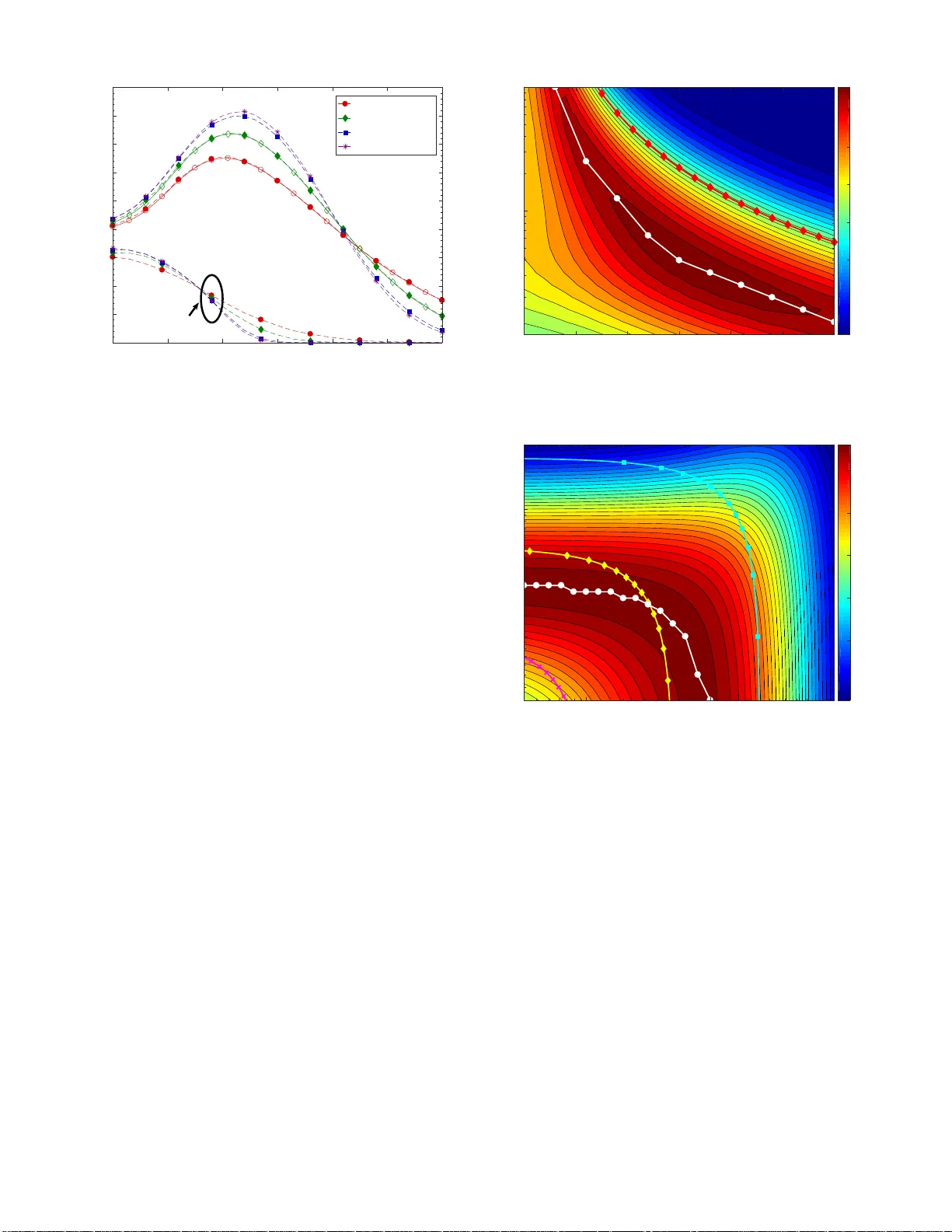
Performance Analysis for Multi-la yer Unmanned Aerial V ehicle Netw orks Dongsun Kim † , Jemin Lee † , and T ony Q. S. Que k ∗ † Daegu Gyeongbuk Institute of Science and T echnology (DGIST), K orea ∗ Singapor e Univ ersity of T echnolo g y an d Design (SUTD), Sing apore Email: yida ever@dgist.ac.kr, jmnlee@dgist.ac.kr , tonyq uek@sutd.ed u .sg Abstract —In this pap er , we provide th e model of the multi - layer aerial network (MAN), composed unmanned aerial vehicles (U A Vs) that distributed in Poisson point process (PPP) with different densities, heights, and transmission power . In our model, we consid er the li n e of sight (LoS) and non- l ine of sight (NLoS) channels which is probabilistically fo rmed. W e fi rstly derive th e probability di stribution fun ction (PDF) of th e main link distance and th e Laplace transform of interference of M AN considering strongest a vera ge receive d p ower -based association. W e then analyze the successful transmission probability (STP) of the MAN and prov ide the u pper bound of th e optimal d ensity that maximizes the STP of the MAN. Through the numerical results, we show the existence of the opti mal height of U A V due to a p erf ormance t radeoff caused by the height of the aerial network (AN ) , and also show th e upper bounds of the optimal densities in terms of the S TP, wh ich decrease wi th the height of the ANs. Index T erms —Stochastic geometry , aerial networks, multi- layer , Po isson p oint p rocess, association rule, optimal density . I . I N T RO D U C T I O N Recent dev elopments in the unman ned aerial vehicle ( U A V) technolog y incr e ase payloads capacity , av erage flight time, and battery ca pacity that enab le s the UA V to play an im- portant role in wireless networks. In the area which n eeds quick d eployment of the b a se station ( BS) due to d isaster or ev ents, UA Vs are expected to act as a tempo ral BS as well [1]. Furtherm ore, the data collection fro m the d evices under certain energy constraints c an be don e by using U A Vs [2]. In additio n, demands on the data acq uisition using UA V in crowd surveillance h av e ar isen [3]. T o utilize U A Vs for the aforemen tioned applications an d services, the resear ch on the establishment o f reliable aerial network (AN) is required . The UA V based wireless co mmunicatio ns has been stud ied in [4]– [6] after mode ling the wireless channel an d th e mob il- ity , which are different from those o f the te r restrial n e tworks. In [4], the probab ility that a link for ms line of sight (LoS), i.e., the Lo S probab ility , is modeled, which is d etermined by th e angle fro m the gro und, and also prop osed the optimal UA V deployment that maximizes the coverage area. In addition, U A V relay networks in cellular networks an d device-to-device commun ications are co nsidered in [5] and [6], respectively . Howe ver, the studies m e ntioned above have considered on ly the small number of UA Vs, wh ich can show the perfo r mance only f or the limited scenar io s. Recently , the research on the ANs, which consist of UA Vs, is p resented in [7], [8] using stochastic geome try , which is a widely-used tool for randomly distributed no des [9]. The coexistence o f AN and the terrestrial cellular networks is studied by considering the distribution of U A Vs as Poisson point pro cess (PPP) in [8]. The coverage p r obability of UA V by using binomial point process (BPP)-based distribution is presented in [ 7]. In additio n, [1 0] studies the multi-tier U A V networks and shows the d ownlink spectr al efficiency of the network via simulations. Howe ver , except f or [10], most of these work s did not co nsider the multiple lay er structu re of ANs. Nev e r theless, no analytical app roach is provided in [10]. In ANs, the UA V hav e limitation on heig ht due to the hardware a nd the law [11]. Further more, as a number of UA V have mobility for serving different service , to avoid the collision between U A Vs and to efficiently manage the resource, it is req uired to have the multiple layer structure in AN which d ifferentiate th e height accordin g to the ro les and typ es of UA V. Therefo re, in this paper, we in vestigate th e perform ance of the mu lti-layer aerial network (MAN) w ith various ty pes of U A V. Specifically , the MAN is composed of K layer ANs that ha ve UA Vs with different transmission power , spa tial densities, and heights. Note that the multip le lay er structure has been con sidered fo r terr e strial networks, wh ich is c a lled as the heterog eneous networks [1 2]–[14]. Howe ver, d ifferent to those works, the heights of no des need to be considered together with the chann e l model which has the LoS probab ility determined by the heigh t of node. This leads to new analysis on the interferenc e a n d the successfu l transmission pr obability (STP) of the MAN considering association rule. T o our best knowledge, there is no analy sis on the STP for mu lti- layer U A V networks consider ing assoc ia tio n rule, LoS, and no n- line of sight (NLoS ) channel. Furthe r more, our analysis on the up per bo und of the optimal d ensity g iv e s u seful insig h ts for futur e MAN im plementation . Our co ntribution can be summarized as follows: • u sing stochastic ge ometry , we newly an alyze the La p lace transform of interferen ce of MAN by considerin g NLoS and LoS chann els with the height- depend ent Lo S pro b- ability; • w e derive the STP when a groun d node selects a U A V ݄ ଵ Ȱ ଵ Ȱ ଶ Ȱ ݄ ଶ 2-layer Aerial Network 1-layer Aerial Network T errestrial Network (0-layer) Fig. 1. An exa mple of two layer AN with ground nodes (i.e., 0 -layer). T he black lines represent the main link from a transmitte r to a recei ver and red dashed lines repre sent interfe rence links which comes from other UA Vs. with association r ules con sidering stron gest av erage re- ceiv ed power for co mmunica tio ns; • to give in sight o n the effect of UA V d ensity on STP, we provide th e up per bound s of the op timal U A V d e nsities of each layer AN that maximize the STP; and • w e show the effects of channel and network par ameters on the op timal heights o f ANs a n d the com patibility of the upp er boun d of op timal den sities. I I . S Y S T E M M O D E L In this section, we pre sen t th e system mode l of MAN with UA V inclu ding the network description an d the channel model. Fur th ermore , we describe the a ssociation ru le which is used to ob tain the p robability distribution f unction (PDF) of the main link distance . A. Multi-layer Aerial Networks W e consider a MAN which con sists of K lay ers of ANs at dif f erent altitudes with a terrestrial network as shown in Fig. 1. W e den ote K as the set of AN lay e r indexes, i.e., K = { 1 , · · · , K } , and layer 0 as the terrestrial network. W e assume U A V in ANs and the gro und nodes in the terrestrial network are distributed according to PPPs [9]. Altho ugh each U A V has giv en p ath scheduled by controller, lo cation of U A Vs at given time is r andom f rom the p erspective of other layers, hence, we use the PPP for the locatio n of the UA V as [8]. Specifically , in the k -layer, the node locations follows a homog e neous PPP Φ k with density λ k and they are at th e fixed altitude h k and transmit with the power P k . Note that the altitude of nodes in the 0 -layer (i.e. , the ter restrial layer) is h 0 = 0 and altitu des of oth er layer s are h k > 0 for k ∈ K . In the MAN, we consider the commun ication fro m a U A V to a ground node. 1 In the communicatio n with U A Vs, we should consider both LoS and NL oS channels since the existence o f obstacles (e.g., buildings) between the transmitter 1 Note that we omitted analysis in cluding the air-to-ai r chan nel in the paper , ev en though our framew ork is readily expa ndable for communication in between U A V which will be presented in the future research. and the receiver can be changed with the altitu d e of U A V. In [ 4], the pro bability of f orming LoS chanel is modeled by a signomial appro ximation of the p r obability of ha ving obstruction s b etween tra nsmitter an d receiver . When a n ode in the k - layer transmits to a g round node, the LoS p robability is defin e d as [ 4] ρ (L) k ( x ) = 1 1 + a exp( − b [sin − 1 h k x − a ]) (1) where a an d b ar e the param eters related with en vironm e nts, and x is the link distanc e between the tran smitter and the receiver . In real environment, U A Vs can act as obstacles, e.g., UA V in 1-layer can block the channel betwe e n ground and 2-la y er AN. Here, we assume existence of UA V d oes not affect the air - to-gro und channel since the density of AN is low , therefo re, the obstruction caused by U A V is negligible. From (1), we can see tha t the LoS pro bability increases with x which means high er altitude gives h igher Lo S prob ability since there will be fewer obstru ctions. The NLoS prob ability is then given as ρ (N) k ( x ) = 1 − ρ (L) k ( x ) . Since each link between a transmitter and a receiver can be in either L oS or NLoS with the probab ilities, ρ (L) k ( x ) and ρ (N) k ( x ) , respec tively , we can divide a set of the k -layer transmitters into th e ones in LoS an d th e ones in NLoS as Φ (L) k and Φ (N) k , respe c ti vely , which are non- homog eneous PPPs. The den sities of no des in Φ (L) k and Φ (N) k with the distance x from a rec eiv e r are, respe c ti vely , defin ed acc o rding to the link d istance x as λ (L) k ( x ) = 2 π xλ k ρ (L) k ( x ) and λ (N) k ( x ) = 2 π xλ k − λ (L) k ( x ) . W e also con sider different chan nel models for links in LoS and NLoS. The pathloss exponen ts for Lo S and the NLoS links are den oted b y α (L) and α (N) , respe c ti vely , a n d gene r ally , 2 ≤ α ( L ) ≤ α ( N ) ≤ 6 . W e co n sider th e Nakagami- m fading for the ch annels of LoS an d the NLo S links, of wh ic h channel gains are respectively presented by G (L) ∼ Γ( m (L) , 1 m (L) ) and G (N) ∼ Γ( m (N) , 1 m (N) ) . Here, we u se m (N) = 1 , which gives Rayleigh fadin g , i.e., G (N) ∼ exp(1 ) , while m (L) ≥ 1 . B. Association Ru le In th is paper, we assume a receiver connects to the transmit- ter , which has the strongest av erage received power d escribed in [1 5]. This can be applied to the scen ario that in th e presen ce of UA V b ased BSs [1], a u ser selects a BS to receive its data. Based on the a ssocia tio n rule, we can pr esent the selected transmitter’ s coo rdinates x main as x main = a rg max x ∈ Φ k ,k ∈K P k k x − x rec k − α x (2) where x rec is the coordin ates the receiver is located, an d α x is the pathloss exponent o f the link between the transmitter at x and the receiver . Based on the association rule above, we can deter mine the PDF of the distance for th e main link fr o m a selected tran s- mitter to a rec e i ver . In co n ven tio nal terrestrial networks, the PDF of main link d istance is determined by the transmission power , the p athloss exponent, an d the link distance. Howe ver , in ANs, we need to addition ally consider the LoS/NLoS probab ilities for all links to the tran sm itter s. W e de note th e channel environmen t by c ∈ { N , L } , where c = N and c = L, respectively , means the L oS and NLoS en vir onmen ts of the link. The PDF of main link distance in c channel cond ition is presented in following lemma. Lemma 1: When a transmitter in the j - la y er u n der the channel en vir onment c is selected , the PDF of m a in link distance Y j ( c ) is giv e n by f Y ( c ) j ( y ) = f V ( c ) j ( y ) A ( c ) j Y k ∈K ,c o ∈ { L, N } , ( k,c o ) 6 =( j,c ) ¯ F V ( c o ) k P k y α ( c ) P j ! 1 α ( c o ) (3) where A ( c ) j is association proba b ility giv en by A ( c ) j = Z y > 0 f V ( c ) j ( y ) Y k ∈K ,c o ∈ { L,N } , ( k,c o ) 6 =( j,c ) ¯ F V ( c o ) k P k y α ( c ) P j ! 1 α ( c o ) .dy (4) Here, V ( c ) j is the distance to the nearest nod e among the nodes in the k - layer u nder the ch annel en viro nment c . ¯ F V ( c ) j ( v ) and f V ( c ) j ( v ) are th e c o mplemen tary cumu lati ve distribution function ( CCDF) and the PDF of V ( c ) j , given by ¯ F V ( c ) j ( v ) = exp " − Z max( v ,h j ) h j 2 π λ j xρ ( c ) j ( x ) dx # , (5) f V ( c ) j ( v ) = 2 π λ j v ρ ( c ) j ( v ) exp " − Z v h j 2 π λ j xρ ( c ) j ( x ) dx # . The PDF f V ( c ) j is 0 when v < h j . Pr oof: The cu mulative distrib u tion func tio n (CDF) of V ( c ) j is giv en by F V ( c ) j ( v ) ( a ) = 1 − exp " − Z max( v ,h j ) h j λ ( c ) j ( x ) dx # (6) where ( a) is fr om th e v o id probability of PPP, and from (6), we have (5).Since the main link h av e smallest pa thloss, probab ility that main link distance is smaller than y when x main ∈ Φ ( c ) j is given by P Y ( c ) j ≤ y ∩ x main ∈ Φ ( c ) j = Z y 0 f V ( c ) j ( v ) P x main ∈ Φ ( c ) j ∩ V ( c ) j = v dv (7) ( a ) = Z y 0 f V ( c ) j ( v ) Y k ∈ K ,c o ∈ { L, N } , ( k,c o ) 6 =( j,c ) P h P j v − α ( c ) ≥ P k V ( c o ) k − α ( c o ) i dv where (a) f rom (2). Th erefore, we der ived the association probab ility as ( 4 ) by y → ∞ . Fu rthermo re, we ca n der i ved the PDF of the m a in link distance as (6). I I I . I N T E R F E R E N C E A N A L Y S I S A N D S U C C E S S F U L LY T R A N S M I S S I O N P RO B A B I L I T Y In this section, we an a lyze the Laplace tran sform of the interferen ce considerin g association rules. Then, we der i ve the STP of the MAN and the upper bo und of the density o f AN that m aximize the STP o f the M AN. A. Laplace T ransform of the Interfer en ce In th e MAN, we first consider interference fro m specific layer and ch annel en viro n ment. Since there is no interferer which have stronger power than main link transmitter, we an- alyze inter ference from specific layer and chann e l to analyze total inter ference. Here, the inter ference from transmitters in the k -layer un der the channe l environment c o is giv e n by I ( c o ) k = X x ∈ Φ ( c o ) k P ( c o ) k ( k x − x rec k ) (8) where P k ( c o ) is the received power from a transmitter which is given by P ( c o ) k ( x ) = P k G ( c o ) x − α ( c o ) . (9) Here, we re present distance b e tween th e transmitter and the receiver as x = k x − x rec k . The Laplace transfo r m of the interferen ce is given in the f o llowing lemma. In the lemm a, we use x ( c ) j ( y ) to r epresent the main link u nder channel en vironmen t c with distanc e y is selected. Lemma 2: When a transmitter in the j - la y er u n der the channel en v ironme n t c with distance y is selected, the L a place transform of the interferen ce fr om the tr ansmitting nodes in the k -lay e r un der the channel environment c o is given by (10), which p r esented on the top of next pa ge, where R ( c,c o ) j,k ( y ) is R ( c,c o ) j,k ( y ) = P k y α ( c ) /P j 1 /α ( c o ) . (11) Pr oof: The Lap la c e transform o f the interfer ence is L I ( c o ) k | x ( c ) j ( y ) ( s ) ( a ) = E Φ ( c o ) k Y x ∈ Φ ( c o ) k 1 1 + sP k x − α ( c o ) m ( c o ) m ( c o ) x ( c ) j ( y ) (12) where (a) is fro m the expec tatio n over chan n el G ( c o ) which giv es the moment- generatin g function (MGF) of Gamma dis- tribution a s [15]. Since λ ( c o ) k ( x ) = 2 π xλ k ρ ( c o ) k ( x ) , the pro ba- bility gener ating function al (PGFL) o f non- homog eneous PPP needs to be o btained as [9] E Y x ∈ Φ ( c o ) k f ( x ) x ( c ) j ( y ) = exp − 2 π λ k Z ∞ R ′ x (1 − f ( x )) ρ ( c o ) k ( x ) dx . (13) In (1 3), selecting a transmitter in th e j -lay er u n der the chann el en vironmen t c b y (2) m e ans there is no inter fering node in th e k -layer under chan nel en vironme nt c o , clo ser th an R ′ = max R ( c,c o ) j,k ( y ) , h k . Combined with ( 12) a nd (13), L I ( c o ) k | x ( c ) j ( y ) ( s ) = exp − 2 π λ k Z ∞ max R ( c,c o ) j,k ( y ) ,h k xρ ( c o ) k ( x ) 1 − 1 1 + sP k x − α ( c o ) m ( c o ) m ( c o ) dx (10) we obtain the Lap lace transfor m interfer e nce under co ndition x ( c ) j ( y ) as ( 10) From Lemma 2 and pr operty o f the Laplace tran sform, we can obtain the Laplace transfor m of the sum of the interferenc e and n o ise as L I | x ( c ) j ( y ) ( s ) = exp( − sσ 2 ) Y k ∈K ,c o ∈{ L,N } L I ( c o ) k | x ( c ) j ( y ) ( s ) (14) where I = P c o ∈{ L,N } k ∈K I ( c o ) k + σ 2 and σ 2 is for the noise power . B. Successful T ransmission Pr obability In this subsection, we define th e STP when the d istance and the channel environment is giv en. Then, we derive the STP of the MAN by using association pro bability and the PDF of the main link distanc e . When the main link is in th e chann el en vironmen t c with the link distance y , th e STP is defined using sign al to interferen ce plus noise ratio ( SINR) as p ( c ) j ( y ) = P h SINR ( c ) j ( d ) > β i (15) where SINR ( c ) j ( d ) = P ( c ) j ( d ) / I , and β is the target SINR, which is related with the tran smission rate. When the associ- ation r ule in (2) is used, the STP o f MAN is p resented in th e following lemma. Lemma 3: The STP of the MAN is given by P = X j ∈K , c ∈{ L, N } Z ∞ h j p ( c ) j ( y ) f Y ( c ) j ( y ) A ( c ) j dy (16) where f Y ( c ) j ( y ) and A ( c ) j is in (3) and (4), p ( c ) j ( y ) is p ( c ) j ( y ) = m ( c ) − 1 X n =0 ( − s ) n n ! d n ds n L I | x ( c ) j ( y ) ( s ) s = S ( c ) j ( y ) , (17) S ( c ) j ( y ) = m ( c ) β P j y − α ( c ) , (18) and L I | x ( c ) j ( y ) ( s ) is in ( 1 4). Pr oof: From the definition of STP, we ha ve the con - ditional STP when a tr ansmitter in j - layer under channel en vironmen t c is selected with the main link distance j represented as p ( c ) j ( y ) ( a ) = E 1 − 1 Γ( m ( c ) ) γ m ( c ) , m ( c ) β P j y − α ( c ) I x ( c ) j ( y ) ( b ) = E m ( c ) − 1 X n =0 ( s I ) n n ! exp ( − s I ) x ( c ) j ( y ) s = S ( c ) j ( y ) (19) where (a) follows from the Gam ma distrib ution of ch annel gain and (b) follows from th e pro perty of lower in c omplete Gamma function. Notice that we derived (18) fro m (b). Using the p roper ty of the f ollowing Laplace transform ( −I ) n L I ( s ) = d n ds n L I ( s ) (20) we o btain ( 17). Furthermo re, fr om th e PDF an d association probab ility in the Lemma 1, we o btain (1 6). When UA Vs are deployed as BSs which serve for gro und receiver , it is impo rtant to maximize STP. In ou r works, we analyze op timal den sity of the tran sm itter . As shown in (16), it is hard to present STP in a closed form, hence, hard to obtain the optimal d e nsities of each AN layer that m aximize ST P. Howe ver, in th e f ollowing co rollary , we p r esent the closed- form upper bou n d of the optimal densities for a special case. Cor ollary 1 : For the case of m (N) = m (L) = 1 , when the optimal d ensity of the j -la y er AN is λ ∗ j , its upper b ound is λ ∗ j ≤ λ b j = 1 2 π ǫ j ( S (L) j ( h j )) (21) where S (L) j ( h j ) is in ( 18), and ǫ j ( s ) is given by ǫ j ( s ) = Z ∞ h j x 1 − ρ (L) j ( x ) 1 + sP j x − α (L) − ρ (N) j ( x ) 1 + sP j x − α (N) ! dx. (22) Pr oof: See App endix A. In Coro llary 1 , the upper bound λ b j is on ly affected by th e network parameter of the j -laye r AN such as h j , but inde- penden t with the d e nsity , height, an d transmission p ower of other ANs. Hen ce, the up per bound of each layer’ s density in MAN can be deter mined ind epende n tly each othe r . Althou gh function ǫ j ( s ) is n ot in the closed fo rm, it is easy to evaluate and analyze. 2 Furthermo re, due to the above inde p endency , we can also obtain the upper bo und of the total d ensity of MAN as λ b T = P k ∈K λ b k . I V . N U M E R I C A L R E S U LT S In this section, we pr esent the numerical results to ev aluate our analysis on the STP o f MAN with single o r two layers of ANs u n der the interferenc e-limited en viro nments. i.e., σ 2 = 0 . For the num e rical results, we use β = 0 . 7 , P k = 1 for all k , α (L) = 2 . 5 , an d α (N) = 3 . 5 . Ex cept for Fig. 2, m (N) = 1 a nd m (L) = 1 are u sed. Mo reover , we use a = 12 . 4231 and b = 0 . 1202 are used for the L oS prob ability , which are determin ed for th e urban ar e a environment in [4]. Fig. 2 shows the STP as a f unction o f the altitude h 1 in single AN f or different values of chan n el coe fficient 2 Note that the upper bound of optimal density λ b j is decrease with height h j under condition β h α (L) j > 1 , h j > 1 which is omitte d in this paper . The conditi ons are readily achie veabl e for aerial netw orks. 0 50 100 150 200 250 300 0 0.1 0.2 0.3 0.4 0.5 0.6 0.7 0.8 0.9 P S f r a g r e p l a c e m e n t s m (L) = 1 m (L) = 3 m (L) = 2 0 m (L) = 100 ρ (L) j ( x ) = 1 h 1 (m) Successful Transmission Probability Fig. 2. STP of single AN according to the al titude h 1 and the LoS coef ficient m (L) when λ 1 = 10 − 5 . ρ (L) j ( x ) = 1 represent the STP when e very link is under L oS channe l. m (L) = { 1 , 3 , 20 , 10 0 } , where λ 1 = 10 − 5 [nodes/ m 2 ]. W e shows the ST P when LoS probab ility is 1 which rep resented with ρ (L) j ( x ) = 1 . Simulation results, obtained f r om Monte Carlo simulatio ns, are presented by the dashed lines with filled markers, while analysis results for m (L) = { 1 , 3 } are presented by the solid lines with unfilled markers. From Fig. 2, we c a n first see that the simulation r esults match well with the an a lysis. W e can also see that for all m (L) , the STP first increases an d th e n de c reases with h 1 . F or small h 1 , as the height increases, the LoS ch annel probability increases, which makes th e main link power stronger and results in the hig her STP. Howe ver, as h 1 keeps in creasing, the main link distance also increases, which makes the main lin k power smaller . As a result, th e optimal value of h eight can be o btained from the tradeoff between the link distance the the LoS probab ility . When the Lo S proba b ility is 1 , th ere is n o tr adeoff, the STP of the AN decr e ase with height, which is same for ρ (L) j ( x ) = 0 . Furthermo re, b y compa ring th e results fo r different m (L) , we can see that for small h 1 , larger L oS coefficient m (L) giv e high e r STP. In sm a ller h 1 , p ower from th e main link is dominan t and mostly LoS ch annel. Since larger LoS chann el coefficient gi ves smaller variance to th e main link channel in smaller h 1 , larger m (L) can give higher STP. Con trary , in larger h 1 , power from the in terferenc e is domin ant. Th erefor e , larger LoS ch annel coefficient g iv es smaller variance to the interferen ce cha n nel which gives lower STP. Howe ver, trends of STP accordin g to th e height are the same for different m (L) . Therefo re, we use m (L) = 1 in the following numer ical r esults because it can g iv e sufficient insigh ts on the per forman ce of MAN. Fig. 3 sho ws the contour of STP as a function of the altitude h 1 and th e d ensity λ 1 of U A V in single AN where m (L) = 1 . W e represent the optimal density as a white line with circles an d the up per bou nd of o ptimal d ensity , obtained from Coro llary 1, as a red lin e with diam o nds. By comparin g the optimal density an d the u p per bound of the 0 50 100 150 200 250 300 10 -6 10 -5 10 -4 0.1 0.2 0.3 0.4 0.5 0.6 P S f r a g r e p l a c e m e n t s h 1 (m) λ 1 (number / m 2 ) Fig. 3. ST P of single AN as functions of the density λ 1 and the height h 1 when m (L) = 1 . T he white line marked by circle s represent s the optimal density when the height is giv en and the red line marked by diamonds represent s the upper bound of the optimal densit y . 10 -6 10 -5 10 -4 10 -6 10 -5 0.1 0.2 0.3 0.4 0.5 0.6 P S f r a g r e p l a c e m e n t s λ 1 (number / m 2 ) λ 2 (number / m 2 ) Fig. 4. STP of 2-layer MAN as functions of the density of 1-laye r λ 1 and the den sity of 2-lay er λ 2 of U A V when m (L) = 1 , h 1 = 100 , and h 2 = 200 . The white line represen ts the optimal λ 2 in giv en λ 1 . The magenta, yello w , and c yan lin es wit h symbol s r epresent s the area whic h ha ve same total d ensity λ T = λ 1 + λ 2 = { 10 − 6 , 10 − 5 . 3 , 10 − 4 . 6 } optimal density , we can notice that the trends according to h 1 are the same. Fr o m Fig. 3, w e can a lso see that as the h eight increases, th e optimal density and its up per bound dec r ease. This is b ecause the n umber of inter fering links in LoS incre a se with h 1 , so the in terferenc e beco mes larger . Fig. 4 sho ws the contour of STP of MAN with two AN as a fun ction of the density of 1 - layer λ 1 and the d e nsity o f 2 -layer λ 2 of U A V, wher e m (L) = 1 , h 1 = 100 , h 2 = 200 . I n this figure, the optim al d e nsity o f 2 -layer λ 2 is presented by a wh ite lin e with circles. The lines with color an d symb ol represent th e STPs of the MAN that h ave th e total density as λ T = λ 1 + λ 2 = { 10 − 6 , 10 − 5 . 3 , 10 − 4 . 6 } [nod es/ m 2 ], respectively . W e can see when density of corre sponding A N is low , the STP incre a se with the den sity , an d when density is high, the STP d ecrease with den sity w h ich is same with th e result of single-layer M AN. Furthermore, fr om the colored lines, we can get th e relationship of o p timal ratio o f densities when the total d ensity of MAN is gi ven. When the total density of the MAN is small, e.g., the ma g enta lin e , the optimal density is λ 2 = λ T . Howe ver, for the large total density , e . g., the cyan line, th e optimal d e n sity is λ 1 = λ T . In other case, as shown in yellow line , we can see the o ptimal is neither λ 1 = λ T nor λ 2 = λ T . Since optimal heig ht of larger AN is low as sho wn in sing le AN, optimal ratio of lower lay er is incre ased with the total density . V . C O N C L U S I O N This paper models the MAN which is wireless networks consist of multi-lay ers o f UA Vs that distributed in PPP with different densities, heights, and powers. W e consider LoS and NLoS chan nel and the stro ngest transmitter association fo r the A N . Our approac h is to derive the PDF of the m ain lin k distance and the Lap lace transfor m of the inter ference for the STP analysis. By ana ly zing the STP, we show that ea ch AN in the MAN have the uppe r boun d of optim al de nsity wh ich is g iven by th e fu n ction of the height of correspo nding AN. In ad dition, our numer ic a l r esults show the tradeoff cau sed by height of the AN, affection of Lo S co efficient, significance of the u p per boun d of the optimal d ensity , and optim al densities and optimal ratio o f densities in th e 2-laye r MAN. Specially , our results show h ig her altitude AN ha ve sparser optimal density and show th at the optimal ratio o f d ensities in the 2-layer MAN is ch anged with the to tal d e nsity of the M AN. A P P E N D I X A. Pr oof of Cor ollary 1 From Lem ma 3, the ST P can be rep resented by P = X j ∈K Z ∞ h j ϕ (L) j ( y ) + ϕ (N) j ( y ) dy , (23) ϕ ( c ) j ( y ) = 2 π ρ ( c ) j ( y ) λ j y exp " − 2 π X k ∈K λ k φ ( c ) j,k y , S ( c ) j ( y ) # , φ ( c ) j,k ( y , s ) = X c o ∈{ L,N } " Z R ′ h k xρ ( c o ) k ( x ) dx + Z ∞ R ′ xρ ( c o ) k ( x ) 1 − 1 1 + sP k x − α ( c o ) dx , and R ′ = max R ( c,c o ) j,k ( y ) , h k , Notice that φ ( c ) j,k ( y , s ) is in- crease with y and s . In add ition, we can deriv e the differential of the total STP with density λ j as ∂ ∂ λ j P = X k ∈K Z ∞ h k ∂ ∂ λ j ϕ (L) k ( y ) + ϕ (N) k ( y ) dy (24) where co mpone n ts inside the in tegral are given b y ∂ ∂ λ j ϕ ( c ) j ( y ) = ϕ ( c ) j ( y ) λ j 1 − 2 πλ j φ ( c ) j,j ( y , S ( c ) j ( y )) (25) ∂ ∂ λ j ϕ ( c ) j ′ ( y ) = ϕ ( c ) j ′ ( y ) − 2 π φ ( c ) j ′ ,j ( y , S ( c ) j ( y )) (26) where j ′ used to represen t j ′ 6 = j . No tice that (25) is differential of th e ST P when main link is j -layer . On the other hand, (26) is d ifferential with λ j for the STP when main link is no t j -lay er , hence the STP always de c r ease with λ k . From (2 5) an d (26), we derive th e ran g e of λ j that m akes the total STP d ecreased with th e λ j . Her e, ϕ ( c ) j ( y ) and λ j is positive for all d omain. Hence, th e total STP decreases with λ j , if following inequ ality holds. max y ,c " 1 2 π φ ( c ) j,j ( y , S ( c ) j ( y )) # ≤ λ j . (27) Furthermo re, a s φ ( c ) j,j ( y , s ) is incre ase with y and s , we can put the minim u m value of y and s which gives φ (L) j,j h j , S (L) j ( h j ) = ǫ j S (L) j ( h j ) . (28) Hence, th e upper b o und of optimal d ensity is given b y (22). R E F E R E N C E S [1] Y . Zeng, R. Zhang, and T . J. Lim, “Wir eless communications with un- manned aerial vehic les: opportunit ies and challe nges, ” IEEE Commun. Mag . , vol . 54, no. 5, pp. 36–42, May 2016. [2] H. Zanjie, N. Hiroki, K. Nei, O. Fumie, M. Ryu, and Z. Baohua, “Resourc e allocati on for data gathering in UA V-aided wireless sensor netw orks, ” in IEEE Conf. on Network Infrastruct ure and Digital Con- tent. IEEE, Jan. 2014, pp. 11–16. [3] N. H. Motlagh, M. Bagaa, and T . T aleb, “U A V-based IoT platform: A cro wd surveil lance use case, ” IEEE Commun. Mag . , vol. 55, no. 2, pp. 128–134, May 2017. [4] A. Al-Hourani , S. Kandee pan, and S. Lardner , “Optimal lap altitud e for maximum cov erage, ” IEEE W irel ess Commun. Lett. , vol. 3, no. 6, pp. 569–572, Jul. 2014. [5] W . Guo, C. Devin e, and S. W ang, “Performance analy sis of micro unmanned airborne communicat ion relays for cellular networks, ” in IEEE Intern ational Symposium on. Communic ation Systems, Netwo rks & Digital Signal Processi ng. IE EE, 2014, pp. 658–663. [6] M. Mozaff ari, W . Saad, M. Bennis, and M. Debbah, “Unmanned aerial vehi cle with underlaid device -to-de vice communicat ions: Performance and t radeoffs, ” IEEE T rans. W ire less Commun. , v ol. 15, no. 6, pp. 3949– 3963, Feb. 2016. [7] V . V . Chetlur and H. S. D hillon, “Do wnlink cov erage analysis for a finite 3-d w ireless network of unmanned aerial vehic les, ” IEE E T rans. Commun. , vol. 65, no. 10, pp. 4543–4558, Jul. 2017. [8] M. M. Azari, F . Rosas, A. Chiumento, and S. Pollin, “Coe xistence of terrestri al and aerial users in cell ular netw orks, ” arXiv pre print arXiv:1710.03103 , Oct. 2017. [Online]. A vail able: https:/ /arxi v .org/pdf/1710 .03103.pdf [9] M. Haenggi and R. K. Ganti, “Interference in large wireless networks, ” F oundations and T re nds in Ne tworking , vol. 3, no. 2, pp. 127–248, 2008. [10] S. Sekander , H. T abassum, and E. Hossain, “Multi-t ier drone archit ec- ture for 5G/B5G cell ular networks: Challenges, trend s, and prospects, ” IEEE Commun. Mag . , vol. 56, no. 3, pp. 96–103, Mar . 2018. [11] S. Chandrasekha ran, K. Gomez, A. Al-Hourani, S. Kandeepan, T . Rasheed, L . Goratti, L. Re ynaud, D. Grace, I. Buc aille, T . W irth et al. , “Designi ng and implement ing future aerial communicat ion networ ks, ” IEEE Commun. Mag . , vol. 54, no. 5, pp. 26–34, May 2016. [12] S. Singh, H. S. Dhillon, and J. G. Andre ws, “Offloa ding in heteroge- neous netwo rks: Modeli ng, analysis, and design insights, ” IEEE T rans. W ire less Commun. , vol . 12, no. 5, pp. 2484–2497, Apr . 2013. [13] H. S. Dhillon, R. K. Ganti , F . Baccelli, and J. G. Andre ws, “Model ing and ana lysis of K-ti er downli nk heteroge neous cellular networ ks, ” IEEE J . Sel. Area s Commun. , vo l. 30, no. 3, pp. 550–560, Apr . 2012. [14] Q. Zhang, H. H. Y ang, T . Q. Quek, and J. Lee, “Hetero geneous cellul ar netw orks with los and nlos transmission s—the role of massive mimo and small cell s, ” IEEE T rans. W ir eless Commun. , vol. 16, no. 12, pp. 7996–8010, Sep. 2017. [15] H. Cho, C. Liu, J. L ee, T . Noh, and T . Q. Quek, “Impact of ele vate d base stations on the ultra-dense networks, ” IEEE Commun. Lett. , Apr . 2018.
Original Paper
Loading high-quality paper...
Comments & Academic Discussion
Loading comments...
Leave a Comment