Digital Predistortion for Hybrid MIMO Transmitters
This article investigates digital predistortion (DPD) linearization of hybrid beamforming large-scale antenna transmitters. We propose a novel DPD processing and learning technique for an antenna sub-array, which utilizes a combined signal of the ind…
Authors: Mahmoud Abdelaziz, Lauri Anttila, Alberto Brihuega
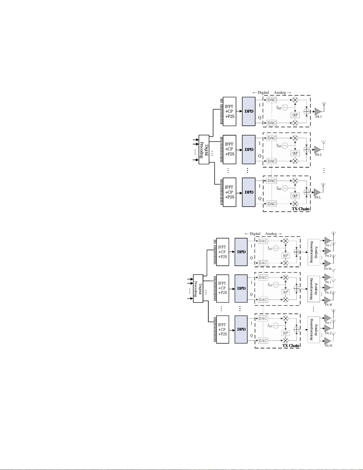
1 Digital Predistortion for Hybrid MIMO T ransmitters Mahmoud Abdelaziz, Member , IEEE, Lauri Anttila, Member , IEEE, Alberto Brihuega, Student Member , IEEE, Fredrik T ufvesson, F ellow , IEEE, Mikko V alkama, Senior Member , IEEE Abstract —This article in vestigates digital predistortion (DPD) linearization of hybrid beamforming large-scale antenna trans- mitters. W e propose a nov el DPD processing and lear ning tech- nique for an antenna sub-array , which utilizes a combined signal of the individual power amplifier (P A) outputs in conjunction with a decorrelation-based lear ning rule. In effect, the proposed approach results in minimizing the nonlinear distortions in the direction of the intended r eceiver . This feature is highly desirable, since emissions in other directions ar e naturally weak due to beamforming. The proposed parameter learning technique requir es only a single observ ation receiver , and theref ore supports simple hardware implementation. It is also shown to clearly outperform the curr ent state-of-the-art technique which utilizes only a single P A for learning. Analysis of the feedback network amplitude and phase imbalances re veals that the technique is rob ust e ven to high levels of such imbalances. Finally , we also show that the array system out-of-band emissions are well- behaving in all spatial directions, and essentially below those of the corresponding single-antenna transmitter , due to the combined effects of the DPD and beamforming . Index T erms —5G, digital predistortion, large-array transmit- ters, hybrid beamforming, power amplifiers, out-of-band emis- sions. I . I N T RO D U C T I O N L ARGE-scale antenna systems are expected to be one of the key enablers of enhanced spectral and energy efficienc y in future wireless communication systems [1], [2]. Utilizing fully-digital beamforming at the transmitter , as most works assume, would mean that each antenna should have a dedicated transmit chain, as depicted in Fig. 1(a). T o relie ve the large hardware costs of such implementations, there has been increasing interest on splitting the beamforming oper- ation between digital and analog domains [3]. One possible implementation of such a hybrid beamforming transmitter is shown in Fig. 1(b). The overall transmitter contains antenna subsystems of M antennas, which are connected to a single RF transmitter chain via an analog beamforming unit. The power ef ficiency of the transmitters is very important in future massi ve antenna arrays with several hundreds of megahertz instantaneous transmit bandwidth, since the con- sumed ener gy per bit is to be kept constant or preferably e ven lowered compared to 4G systems [1], [2]. The po wer ef ficiency Mahmoud Abdelaziz, Lauri Anttila, Alberto Brihuega, and Mikk o V alkama are with the Laboratory of Electronics and Communications Engineering, T ampere Uni versity of T echnology , T ampere, Finland. Fredrik T ufvesson is with the Department of Electrical and Information T echnology , Lund University , Lund, Sweden. This work was supported by T ekes, Nokia Bell Labs, Huawei T echnologies Finland, TDK-EPCOS, Pulse Finland and Sasken Finland under the 5G TRx project, and by the Academy of Finland under the projects 288670 “Massiv e MIMO: Advanced Antennas, Systems and Signal Processing at mm- W aves”, 284694 “Fundamentals of Ultra Dense 5G Networks with Application to Machine T ype Communication”, and 301820 “Competitive Funding to Strengthen University Research Profiles”. 90 ⁰ 90 ⁰ 90 ⁰ D A C D A C D A C D A C D A C D A C D P D f RF D P D f RF D P D f RF I Q I Q I Q ← D i g i t a l A n a l o g → I F F T + C P + P 2 S D i g i t a l P r e c o d i n g I F F T + C P + P 2 S I F F T + C P + P 2 S P A 1 P A 2 P A L T X C h a i n (a) Digital MIMO transmitter architecture with per antenna/P A digital predistortion. P A 2 P A 1 P A M A n a l o g B e a m f o r m i n g P A 2 P A 1 P A M A n a l o g B e a m f o r m i n g P A 2 P A 1 P A M A n a l o g B e a m f o r m i n g 90 ⁰ 90 ⁰ 90 ⁰ D A C D A C D A C D A C D A C D A C D P D f RF D PD f RF D PD f RF I Q I Q I Q ← D i g i t a l A n a l o g → I F F T + C P + P 2 S D i g i t a l P r e c o d i n g I F F T + C P + P 2 S I F F T + C P + P 2 S T X C h a i n (b) Hybrid MIMO transmitter architecture with per sub-array digital predistor - tion. Fig. 1. Digital versus Hybrid MIMO transmitter architectures. Thick lines correspond to complex I/Q processing. of the P As, which are the most power hungry components in the transmitter (independent of whether fully-digital or hybrid beamforming is used), therefore needs to be high. Thus, lo w-cost, small-size and highly energy-ef ficient, and therefore highly nonlinear P As operating close to saturation, are expected to be adopted. Some recent studies hav e in vestigated the impact of P A 2 P A 2 P A 1 P A M A n al o g B e a m f o r m i n g TX c h a i n () xn () xn D P D () yn I n t e n d e d R e c e i v e r 1 () xn () M xn 2 () xn V i c t i m R e c e i v e r Fig. 2. Block diagram of a single sub-array in a hybrid MIMO transmitter . The effecti ve signal radiated towards the intended RX direction, y ( n ) , is the superposition of the individual antenna outputs when assuming ideal beamforming and free-space LoS conditions. The worst-case victim RX, in terms of OOB radiation, lies also in the direction of the main beam. nonlinearities on massive MIMO transmitters [4]–[10]. These studies show that the spectral efficienc y and the energy effi- ciency , both of which are fundamental objectiv es of massive MIMO, are compromised. In [5], the out-of-band radiation due to P A nonlinearity was analyzed in both single antenna and massiv e MIMO transmitter scenarios, assuming a memoryless polynomial model for each P A unit. It was shown that the adjacent channel leakage ratio (A CLR) due to P A nonlinearity in the massiv e MIMO scenario is, on av erage, equal to the single antenna scenario when transmitting with the same total sum-power . This implies that when a highly nonlinear P A is used per RF chain, as mentioned earlier , significant out-of- band distortion can occur in massi ve MIMO transmitters that can easily interfere with neighboring channel transmissions and/or violate the spurious emission limits, as also demon- strated in [6]. In terms of the impact of hardw are impairments on the transmitted signal quality , it was shown in [6] that the error vector magnitude (EVM) degradation due to P A nonlinearity can compromise the spectral efficienc y of the massive MIMO base station. In [6], at least 6 dB backof f was shown to be required in order to reach the maximum tar geted data rate. Moreover , in [7], the authors demonstrated that when practical P A models are used in a massiv e MIMO base station, the signal to interference and noise ratio (SINR) at the user receiv er could be significantly degraded. In [10], a more detailed study was conducted re garding the out-of-band radiation in massive MIMO transmitters when the P A nonlinearity is considered. It was shown in [10] that when assuming a single user per array , and free-space line- of-sight (LoS) propagation with ideal beamforming, the most harmful emissions are in the same direction as the main beam. It was also shown that under this assumption, the in-band and out-of-band unwanted emissions due to the nonlinear P As are identical to the single antenna case in the direction of the main beam to wards the intended RX. Thus, the worst case scenario will occur when a victim user lies in the same direction as the intended user , as sho wn in Fig. 2. In general, applying backoff to overcome the P A distortion is not an attractive solution since it requires using larger P As operating in the linear region, assuming a giv en transmit sum-power requirement. As a result, the cost and size of each RF chain would increase and the energy efficiency would decrease, which directly translates to increased running costs in terms of power supply and cooling. Thus a more intriguing solution is to use smaller P As that operate more efficiently close(r) to saturation, while using a low complexity linearization method to reduce both the in-band and the out- of-band distortion per RF chain. This is the main scope of this paper . Digital predistortion has been studied in the massiv e MIMO context in [11]–[14]. In [11], fully digital beamforming was assumed, and therefore a dedicated DPD unit for each trans- mitter is required. In [12]–[14], DPD in hybrid MIMO was in vestigated. T o this end, as the predistorter is operating in the digital baseband, a single DPD should linearize all the M P As simultaneously . This is essentially an underdetermined problem and will commonly lead to reduced linearization performance for the individual P As. In [12], the DPD learning was based on measuring only one of the P As, while in [13], the P As per sub-array were assumed to be identical. Howe ver , these approaches will work satisf actorily only if the P A nonlinear characteristics are very similar - an assumption that is commonly far from practical. In [14], a single DPD per sub-array was proposed based on the direct learning approach. The learning criteria is based on minimizing the sum of squared errors between the input and output signals of the P As while using a dedicated observation RX chain per P A. The work in [14] was shown to provide better results compared to estimating the DPD parameters using only one of the P A elements. Howe ver , only memoryless DPD processing was proposed in [14] and therefore it was only tested using memoryless P As, which is not a realistic case, especially when considering relativ ely wide-band transmit signals with tens or hundreds of MHz bandwidth. In this paper , we propose a new structure for DPD learning in hybrid MIMO transmitters, which is both simpler and more ef fective than the current state-of-the-art. W e argue that, because the individual P As can anyway not be linearized perfectly , the objective should be to primarily reduce the distortions in the direction of the intended receiv er . For the other spatial directions, [10] showed that the out-of-band emissions will be diluted due to non-coherent superposition of the transmit signals. This philosophy leads us to use the superposition signal of the individual P A outputs for DPD learning, and thus using only a single observation RX chain. In terms of main beam linearization, the proposed DPD is shown to give superior results compared to using only a single P A for learning. T o assess how the emissions behav e in other spatial directions under the proposed DPD solution, we apply a similar numerical approach as [10]. Our results indicate that while the proposed DPD significantly reduces the unwanted emissions in the main beam direction, the out- of-band emissions in the other spatial directions are also well-behaving and essentially belo w those of the reference single-antenna transmitter due to the combined ef fects of DPD and beamforming. The sensitivity of the technique to amplitude and phase imbalance between the feedback paths is also analyzed, and the effects are shown to be negligible with realistic imbalance values. Moreov er , the proposed DPD structure and learning are dev eloped taking into consideration the unav oidable memory ef fects in the P As, and can in general 3 be adopted at below 6 GHz bands as well as at mmW a ve fre- quencies. For realistic performance assessment, the proposed DPD is tested and ev aluated using realistic P A models with memory which are extracted from actual hardware equipment that can be used in a real massive MIMO base station 1 . The rest of the article is structured as follows. Section II analyzes the nonlinear distortion created by the P As of a single sub-array in the direction of the intended RX. Section III then introduces the proposed DPD structure and parameter learning method. The impacts of amplitude and phase mismatches between the feedback paths are then analyzed in Section IV. Section V presents some realistic simulation results using practical RF measurement based P A models with memory . Finally , Section VI concludes the findings of this paper . I I . M O D E L I N G A N D M E A S U R I N G N O N L I N EA R D I S T O RT I O N I N H Y B R I D M I M O T X S U B - A R R A Y S In this section, the nonlinear distortion due to the P As in a hybrid MIMO transmitter architecture is analyzed as a first essential step tow ards developing an efficient DPD structure and parameter learning solution. Considering a single sub- array as shown in Fig. 2, yet without any DPD processing (i.e., ˜ x ( n ) = x ( n ) ), the baseband equi valent input and output signals of the m th P A, assuming a parallel Hammerstein (PH) P A model [15]–[17], read x m ( n ) = w m x ( n ) (1) y m ( n ) = P X p =1 p, odd f m,p,n ? | x m ( n ) | p − 1 x m ( n ) , (2) where x ( n ) denotes the baseband equiv alent transmit signal of the considered sub-array , x m ( n ) and y m ( n ) refer to the baseband equiv alent input and output signals of the P A unit in the m th antenna branch while w m denotes the corresponding beamforming coef ficient. Furthermore, f m,p,n denotes the p th order PH branch filter impulse response for the P A unit of the antenna branch m , and ? is the conv olution operator which is defined as f m,p,n ?x m ( n ) = P N l =0 f m,p,l x m ( n − l ) , where N is the filter memory order . Assuming | w m | = 1 , i.e., only phase rotations are performed in the analog beamforming stage, the transmit signal of the m th antenna element can be equiv alently re-written as y m ( n ) = w m P X p =1 p, odd f m,p,n ? | x ( n ) | p − 1 x ( n ) . (3) In general, the beamforming coef ficients w m are chosen such that most of the allocated power is radiated to wards the intended RX direction. Therefore, in order to further analyze the harmful radiated emissions, we primarily consider the non- linear distortion which is radiated from the TX array towards the intended RX [10]. Assuming next, for simplicity , ideal beamforming in free-space line-of-sight (LoS) conditions, the 1 Lund University Massive MIMO testbed, http://www .eit.lth.se/mamitheme The P A models are a vailable through IEEEXplore. P A 2 P A 1 P A M A n al o g B e a m f o r m i n g A n t i - b e a m f o r m i n g , an d c o m b i n i n g TX c h a i n R X c h a i n () xn () xn D P D B as i s f un c t i o n s G e n e r at i o n D P D F i l t e r D P D Ma i n P a t h P r o c e s s i n g D e c o r r e l a t i o n - b as e d D P D l e ar n i n g () zn Fig. 3. Block diagram of the proposed DPD system for one sub-array . individual signals y m ( n ) will coherently add up to construct an equiv alent receiv ed or observed signal y ( n ) of the form y ( n ) = M X m =1 w ∗ m y m ( n ) (4) = M X m =1 P X p =1 p, odd f m,p,n ? | x ( n ) | p − 1 x ( n ) . (5) In this work, we consider the out-of-band (OOB) emissions in the worst case scenario when the victim RX lies in the same direction as the intended RX, as discussed also in [10] and in the Introduction. In such scenarios, when assuming a single user per sub-array , the OOB emissions are similar to the classical emission scenarios and can be quantified using the adjacent channel leakage ratio (A CLR) metric. Howe ver , the exact method of ev aluating the ACLR in large-array transmitters has not been decided yet in, e.g., 3GPP mobile radio network standardization. In this work we measure the A CLR based on the effecti ve combined signal y ( n ) , which is essentially the sum of outputs from all the antenna elements per sub-array in the intended RX direction. On the other hand, the in-band distortion of the ef fectiv e radiated signal y ( n ) will be very similar to the classical scenarios and will be quantified using the error vector magnitude (EVM) metric in this work. Finally , we note that while the basic modeling and DPD processing dev elopments in this article b uild on the PH or memory polynomial (MP) based approach, also more elaborate nonlinear models such as the generalized memory polynomial (GMP) [18] can be adopted in a straight-forward manner . I I I . P RO P O S E D D P D S T R U C T U R E A N D P A R A M E T E R L E A R N I N G S O L U T I O N In the h ybrid MIMO architecture, each sub-array is fed by a single RF upcon version chain. This implies that only a single DPD stage can be used per sub-array , as shown in Fig. 3. From one side, this reduces the comple xity of the o verall transmitter system in terms of the DPD processing, while on the other side it makes the linearization problem much more challenging, both from the DPD main path processing structure and the parameter learning perspectiv es, as the e xact characteristics of the in volved M parallel P As are generally different. 4 A. Pr oposed DPD Structur e Based on the nonlinear distortion analysis in the previous section, we formulate the proposed DPD structure and learning philosophy in this section keeping in mind that the main objectiv e is to primarily minimize the harmful emissions in the intended RX direction, i.e., the in-band and OOB nonlinear distortion products in the effecti ve combined signal y ( n ) expressed in (5). W e first re write (5) such that the linear and nonlinear terms are separated as follows y ( n ) = M X m =1 f m, 1 ,n ? x ( n ) + M X m =1 P X p =3 p, odd f m,p,n ? | x ( n ) | p − 1 x ( n ) (6) = f tot, 1 ,n ? x ( n ) + P X p =3 p, odd f tot,p,n ? | x ( n ) | p − 1 x ( n ) , (7) where f tot,p,n = P M m =1 f m,p,n . From (7), it can be seen that the nonlinear term of y ( n ) is composed of a linear combination of the static nonlinear (SNL) basis functions u p ( n ) = | x ( n ) | p − 1 x ( n ) and their delayed replicas. Further- more, the ef fective branch filters f tot,p,n depend only on the sums of the individual P A model branch filters f m,p,n , m = 1 , 2 , . . . , M . In general, we focus our attention mostly on the nonlinear distortion, since the linear distortion term in (7) is anyway usually equalized at the recei ver side and can thus be considered to be part of the o verall wireless communications channel. Consequently , the ke y idea of the proposed DPD structure is to inject a proper additional lo w-power cancellation signal, with structural similarity to the nonlinear terms in (7), at the input of the P As of the considered sub-array such that the radiated in-band and OOB nonlinear distortion products are minimized in the intended RX direction. Stemming from the abo ve modeling, an appropriate digital injection signal can be obtained by adopting the SNL ba- sis functions u q ( n ) , q = 3 , 5 , . . . , Q, combined with proper filtering using a bank of DPD filters, α q ,n , with memory order N q . In general, incorporating such DPD processing with polynomial order Q , the output signal of the DPD processing stage of the considered sub-array reads ˜ x ( n ) = x ( n ) + Q X q =3 q , odd α ∗ q ,n ? u q ( n ) . (8) Here, and in the continuation, we use ˜ ( . ) variables to indicate DPD-based processing and corresponding signals. The achiev- able suppression of the nonlinear distortion depends directly on the selection and optimization of the DPD filter coefficients α q ,n . This is addressed in detail in the next subsection. W e also note that an additional branch filter can be applied to the linear signal term in (8) if, e.g., linear response pre-equalization is pursued. B. Pr oposed Combined F eedback based DPD Learning The main philosophy of the proposed DPD learning is to minimize the correlation between the nonlinear distortion ra- diated from the considered sub-array and the SNL basis func- tions u q ( n ) and their delayed replicas. Once such correlation minimization is achieved, the lev el of the nonlinear distortion is significantly reduced. This type of a decorrelation-based learning criteria has been introduced earlier by the authors in [11], [19] in the context of single-antenna transmitters. In this article, a similar approach is adopted and dev eloped in the context of DPD parameter learning in hybrid MIMO transmitters. In order to extract the effecti ve nonlinear distortion at the sub-array output, while also using only a single RX chain in the observation system, we propose to explicitly combine the individual outputs of each P A per sub-array . This can be real- ized by using M directional couplers followed by a co-phasing (or “anti-beamforming”) and combining module before the feedback RX chain as shown in Fig. 3. The purpose of the anti- beamforming is to counteract the effect of the beamforming coefficients in the analog beamforming module such that the observed signal in the feedback observation RX corresponds to the actual signal radiated in the intended RX direction ( y ( n ) ). Another practical alternative is to momentarily set all beamforming weights to one ( w m = 1 for all m ), for the period of DPD parameter learning, and then simply sum up the individual P A output signals, which essentially yields the same observation wav eform. Consequently the baseband equi valent observ ation signal at the feedback RX output, denoted by z ( n ) , while assuming that | w m | = 1 , reads z ( n ) = M X m =1 w ∗ m g c y m ( n ) (9) = g c M X m =1 | w m | 2 P X p =1 p, odd f m,p,n ? | x ( n ) | p − 1 x ( n ) (10) = g c M X m =1 P X p =1 p, odd f m,p,n ? | x ( n ) | p − 1 x ( n ) , (11) where g c denotes the coupling factor in the indi vidual feedback paths. For presentation simplicity , g c is assumed abov e to be identical in all feedback branches. Practical mismatches between the feedback branches will then be considered in detail in Section IV as well as in the numerical e xperiments in Section V. Notice also that since the anti-beamforming stage cancels or removes the effects of the specific beamforming coefficients, parameter learning can take place during the normal operation of the transmitter . Alternatively , a dedicated learning period can also be adopted. In order to utilize the observ ation signal z ( n ) in the DPD learning, we can rewrite (11) as z ( n ) = Gx ( n ) + d ( n ) , (12) where G is the effecti ve complex linear gain while d ( n ) corresponds to the total effecti ve distortion signal due to the P A units. The actual error signal which is then used for the decorrelation-based parameter learning is calculated as follows e ( n ) = z ( n ) − ˆ Gx ( n ) , (13) 5 where ˆ G is the effecti ve linear gain estimate which can be obtained in practice by using, e.g., block least squares (LS). This error signal seeks to provide information at waveform lev el about the currently prev ailing nonlinear distortion sam- ples in the effecti ve combined signal relativ e to the ideal signal samples x ( n ) . In cases where there is substantial frequency- selectivity in the effecti ve linear response, an actual multitap filter can be estimated and utilized in (13). In general, the SNL basis functions u q ( n ) = | x ( n ) | q − 1 x ( n ) and their delayed replicas are strongly mutually correlated, and thus basis function orthogonalization is required in order to hav e a faster and smoother conv ergence of the DPD param- eter estimates during the learning process [20]. In principle, any suitable orthogonalization/whitening transformation with a triangular orthogonalization matrix can be adopted, e.g., QR decomposition (Gram-Schmidt type) or one based on Cholesk y decomposition of the cov ariance matrix of the basis functions. For clarity , the orthogonalized basis functions are denoted in the following by s q ( n ) . The actual block-adaptive decorrelation-based DPD coef fi- cient update, with learning rate µ , then reads ¯ α ( i + 1) = ¯ α ( i ) − µ [ e ( i ) H S ( i )] T , (14) where e ( i ) = [ e ( n i ) ... e ( n i + B − 1)] T is a block of B observed samples of the error signal e ( n ) , while n i denotes the index of the first sample within block i . Furthermore, ¯ α ( i ) in (14) is defined as follo ws α q ( i ) = [ α q , 0 ( i ) α q , 1 ( i ) ... α q ,N q ( i )] T (15) ¯ α ( i ) = [ α 3 ( i ) T α 5 ( i ) T ... α Q ( i ) T ] T , (16) while S ( i ) in (14) is defined using the orthogonal basis function samples s q ( n ) as s q ( n i ) = [ s q ( n i ) ... s q ( n i − N q )] (17) S q ( i ) = [ s q ( n i ) T ... s q ( n i + B − 1) T ] T (18) S ( i ) = [ S 3 ( i ) S 5 ( i ) ... S Q ( i )] . (19) The updated DPD coefficients ¯ α ( i + 1) are then used to filter the next block of B samples, and the process is iterated until con vergence. Using the adaptiv e filter update in (14), it can be shown that the learning algorithm con verges to the point where the residual nonlinear distortion becomes uncorrelated with the adopted orthogonalized basis functions, and hence the name decorrelation-based learning. Finally , we note that the above decorrelation-based iterati ve learning rule can be either executed during the specific param- eter learning/calibration periods, or alternativ ely , be ev en run- ning continuously , in conjunction with the anti-beamforming based combined feedback signal, if one wishes to track the potential changes in the P A characteristics as accurately as possible. This is because e ven though the served intended receiv er(s) change in practical radio networks commonly at 1 ms time scale (the scheduling interval in L TE/L TE-Advanced mobile radio networks), or ev en faster , the anti-beamforming stage makes the feedback signal independent of the actual value of the intended receiv er direction, and hence the algo- rithm can run continuously . I V . I M PAC T O F M I S M A T C H E S B E T W E E N T H E F E E D BA C K B R A N C H E S In order to obtain the feedback signal z ( n ) which is used for the DPD learning, the outputs of the individual P As are first extracted using M directional couplers, then co-phased and combined in the analog domain before being applied into a single observation RX chain which brings the observation signal down to baseband, as shown in Fig. 3. Consequently , in the actual physical circuit implementation, there can be amplitude and phase mismatches between the M observation branches prior to and within combining. In the following, these mismatches are analyzed and their effect on the proposed DPD system and its performance is discussed. Assuming m = β m e j φ m denotes the complex gain devia- tion relative to the nominal coupling factor g c in the m th feed- back coupler path, where β m and φ m are the corresponding gain and phase mismatches, the baseband equiv alent combined observation signal z ( n ) then reads z ( n ) = M X m =1 g c (1 + m ) P X p =1 p, odd f m,p,n ? | x ( n ) | p − 1 x ( n ) (20) = g c M X m =1 P X p =1 p, odd f m,p,n ? | x ( n ) | p − 1 x ( n ) + g c M X m =1 m P X p =1 p, odd f m,p,n ? | x ( n ) | p − 1 x ( n ) . (21) When | m | 1 , the second term in (21) can be essentially neglected and we return back to the expression in (11). How- ev er , when the gain and phase mismatches start to increase, the combined observation signal starts to gradually degrade. Meanwhile, the assumption that the combined observation signal z ( n ) is composed of a linear combination of the SNL basis functions and their delayed replicas will still hold. In order to more explicitly analyze the impact of such gain and phase mismatches between the feedback branches on the DPD learning, and consequently the DPD performance, in closed-form, we proceed as follows. For mathematical tractability , we assume simple third-order memoryless pro- cessing in both the P A and DPD models. For reference, we first deri ve the optimum decorrelation-based DPD coefficient without any mismatches, being then followed by the cor- responding optimum coefficient deriv ation under the branch mismatches. This allows us to analytically address how much the mismatches affect or bias the DPD coef ficient, in the simple example case of a third-order DPD system. Now , the DPD output signal ˜ x ( n ) with third-order memo- ryless DPD processing reads ˜ x ( n ) = x ( n ) + α ∗ 3 | x ( n ) | 2 x ( n ) , (22) where α 3 is the third-order DPD coef ficient applied in its conjugated form in order to conform with the notation adopted in Section III. The corresponding output of the m th P A unit with DPD becomes ˜ y m ( n ) = w m [ f m, 1 ˜ x ( n ) + f m, 3 | ˜ x ( n ) | 2 ˜ x ( n )] . (23) 6 Then, the combined observation at the feedback receiver output, with DPD included, reads ˜ z ( n ) = M X m =1 w ∗ m g c ˜ y m ( n ) (24) = g c M X m =1 ( f m, 1 ˜ x ( n ) + f m, 3 | ˜ x ( n ) | 2 ˜ x ( n )) . (25) Substituting (22) into (25) yields ˜ z ( n ) = x ( n ) g c M X m =1 f m, 1 + | x ( n ) | 2 x ( n ) g c M X m =1 ( α ∗ 3 f m, 1 + f m, 3 ) + | x ( n ) | 4 x ( n ) g c M X m =1 ( α 3 + 2 α ∗ 3 ) f m, 3 + | x ( n ) | 6 x ( n ) g c M X m =1 (2 | α 3 | 2 + α ∗ 2 3 ) f m, 3 + | x ( n ) | 8 x ( n ) g c M X m =1 α ∗ 3 | α 3 | 2 f m, 3 . (26) Since the decorrelation-based learning algorithm aims at min- imizing the correlation between the error signal observed at feedback receiv er output, i.e., e ( n ) = ˜ z ( n ) − ˆ Gx ( n ) , and the SNL third-order basis function | x ( n ) | 2 x ( n ) , we ev aluate the expression of this correlation I E | x ( n ) | 2 x ∗ ( n ) e ( n ) in closed- form while assuming a perfect estimate of the effecti ve linear gain G . W e first write I E | x ( n ) | 2 x ∗ ( n ) e ( n ) = I E " | x ( n ) | 6 g c M X m =1 ( α ∗ 3 f m, 1 + f m, 3 ) # + I E " | x ( n ) | 8 g c M X m =1 ( α 3 + 2 α ∗ 3 ) f m, 3 # + I E " | x ( n ) | 10 g c M X m =1 (2 | α 3 | 2 + α ∗ 2 3 ) f m, 3 # + I E " | x ( n ) | 12 g c M X m =1 α ∗ 3 | α 3 | 2 f m, 3 # . (27) In order to analytically calculate the DPD coef ficient α 3 that minimizes I E | x ( n ) | 2 x ∗ ( n ) e ( n ) , we set (27) to zero. While neglecting the higher-order terms by assuming that they are v anishingly small, as α 3 is in general a small number with any reasonable P A nonlinear response characteristics, the correlation minimization approach yields α ∗ 3 ,opt I E | x ( n ) | 6 g c M X m =1 f m, 1 + ( α 3 ,opt + 2 α ∗ 3 ,opt )I E | x ( n ) | 8 g c M X m =1 f m, 3 = − I E | x ( n ) | 6 g c M X m =1 f m, 3 . (28) Then, denoting P M m =1 f m, 3 / P M m =1 f m, 1 by F 31 we get the following expression α ∗ 3 ,opt = − F 31 1 + ( α 3 ,opt + 2 α ∗ 3 ,opt ) I E | x ( n ) | 8 I E | x ( n ) | 6 . (29) T aking the complex conjugate of (29) provides us with a second equation in α 3 ,opt and α ∗ 3 ,opt which reads α 3 ,opt = − F ∗ 31 1 + ( α ∗ 3 ,opt + 2 α 3 ,opt ) I E | x ( n ) | 8 I E | x ( n ) | 6 . (30) The expressions in (29) and (30) allow then solving for α 3 ,opt which yields α 3 ,opt = − F ∗ 31 (1 + F 31 I E 86 ) 3 | F 31 | 2 I E 2 86 + 2I E 86 ( F 31 + F ∗ 31 ) + 1 , (31) where I E 86 = I E | x ( n ) | 8 I E | x ( n ) | 6 . This expression serves as reference and comparison point for addressing the branch mismatch impact. Next, we introduce amplitude and phase mismatches in the feedback coupling paths and re-deri ve the expression for α 3 ,opt in order to e xamine the ef fect of such mismatches on the proposed learning algorithm. The optimum DPD coef ficient with mismatches included is denoted by ¯ α 3 ,opt , for notational clarity . The feedback observation signal ˜ z ( n ) , with mismatches included, now reads ˜ z ( n ) = g c M X m =1 (1 + m )( f m, 1 ˜ x ( n ) + f m, 3 | ˜ x ( n ) | 2 ˜ x ( n )) . (32) Performing similar analysis steps as above, we get the fol- lowing expression for the decorrelation-based optimum DPD coefficient ¯ α 3 ,opt , expressed as ¯ α ∗ 3 ,opt = − P M m =1 f m, 3 (1 + m ) P M m =1 f m, 1 (1 + m ) × 1 + ( ¯ α 3 ,opt + 2 ¯ α ∗ 3 ,opt ) I E | x ( n ) | 8 I E | x ( n ) | 6 . (33) Then, denoting P M m =1 f m, 3 (1 + m ) / P M m =1 f m, 1 (1 + m ) by ¯ F 31 we get the following expression ¯ α ∗ 3 ,opt = − ¯ F 31 1 + ( ¯ α 3 ,opt + 2 ¯ α ∗ 3 ,opt ) I E | x ( n ) | 8 I E | x ( n ) | 6 . (34) Then, using similar analysis steps as in the case without mismatches, the expression for ¯ α 3 ,opt with mismatches can be shown to read ¯ α 3 ,opt = − ¯ F ∗ 31 (1 + ¯ F 31 I E 86 ) 3 | ¯ F 31 | 2 I E 2 86 + 2I E 86 ( ¯ F 31 + ¯ F ∗ 31 ) + 1 , (35) where ¯ F 31 is giv en by ¯ F 31 = P M m =1 f m, 3 + P M m =1 f m, 3 m P M m =1 f m, 1 + P M m =1 f m, 1 m . (36) When using a relativ ely large number of antennas per sub- array , M , then P M m =1 f m, 3 m → c I E[ f m, 3 m ] where c is a scaling constant, and similarly P M m =1 f m, 1 m → c I E[ f m, 1 m ] . Assuming m is a random variable with zero mean, and since m is, in general, independent of both f m, 3 and f m, 1 , then 7 ¯ F 31 ≈ F 31 , and consequently (35) reduces to (31). Thus, the analysis shows that the mismatches in the feedback branches hav e a very small effect on the proposed decorrelation-based DPD parameter learning, and consequently its performance. Thus, the proposed sub-array DPD system is robust against the possible feedback coupling branch mismatches, a finding that we also (re)confirm using the numerical experiments in the following section. W e note that while the analytical mismatch analysis abov e builds on the simplifying assumption of third- order memoryless models, our numerical experiments will include higher-order nonlinearities and memory in both the P A units as well as in the DPD processing stage. V . N U M E R I C A L E X P E R I M E N T S In this section, a quantitativ e performance analysis of the proposed DPD solution is presented using comprehensive Matlab simulations with practical measured models for P As with memory . The measured P A models are obtained from the Lund Univ ersity massiv e MIMO test-bed which is one of the most established large-array transceiv er platforms currently av ailable, and includes 100 P A units overall. The proposed DPD which uses the combined feedback signal is compared against a classical DPD approach which uses only a single P A output for learning. The P A models are 11th-order PH models extracted from indi vidual USRP modules that are used in the Lund massiv e MIMO hardw are testbed transmitting at 2 GHz RF frequency . The sample rate used to extract these models is 120 MHz. The credibility and practicability of the results presented in this section is thus high when compared to state-of-the-art works in DPD for hybrid MIMO transmitters which usually assume substantially more simple P A models without memory [14], or ev en that all P A units in such array structure would be identical [12], [13]. The signal used in the P A measurements as well as in our DPD simulations is a 20 MHz OFDM signal with 16-QAM subcarrier modulation. Iterativ e clipping and filtering-based P APR reduction is applied to the transmit signal limiting the actual P APR of the signal to approximately 8.3 dB [21]. The output power spectra of 16 different P As of representativ e nature are shown in Fig. 4. A. DPD P erformance Results and Analysis First, we address the achiev able linearization performance in the intended RX direction. Both the inband waveform purity and the adjacent channel interference due to spectral regro wth are quantified using the error vector magnitude (EVM), and the ACLR metrics, respectiv ely [22]. The EVM and ACLR are calculated for the effecti ve combined signal in the intended RX direction as explained in the previous sections. The EVM is defined as E V M % = q P err or /P ref × 100% , (37) where P err or is the power of the error signal, defined as the difference between the ideal symbol values and the corre- sponding symbol rate complex samples at the array output in the intended RX direction, both normalized to the same av erage power , while P ref is the reference power of the ideal symbol constellation. T ypically in EVM e valuations, linear -60 -50 -40 -30 -20 -10 0 10 20 30 40 50 60 -90 -80 -70 -60 -50 -40 -30 -20 -10 0 Fig. 4. Normalized indi vidual P A output spectra of 16 different P A models extracted from a true large-array transmitter system at 120 MHz sample rate. The transmitted OFDM carrier is 20 MHz wide with 16-QAM subcarrier modulation, and the P APR is 8.3 dB. An 11th-order PH model with memory is extracted per P A. The passband power of every P A model is normalized to 0 dB. T ABLE I E V M A N D AC L R R E S U L T S EVM ( % ) A CLR L / R (dBc) W ithout DPD 3.17 40.48 / 40.58 W ith single P A learning 2.09 52.01 / 51.91 W ith proposed DPD 1.85 63.63 / 61.42 distortion of the transmit chain is equalized prior to calculating the error signal [23], and this is also what we do in this w ork. In turn, the ACLR is defined as the ratio of the emitted powers within the wanted channel ( P wanted ) and the adjacent channel ( P ad j acent ), respectively [24], interpreted also for the ef fectiv e combined signal in the direction of the intended RX, namely AC LR dB = 10 log 10 P wanted P ad j acent . (38) In this work, the channel bandwidth of the wanted signal is defined as the bandwidth which contains 99% of the total emitted po wer in the main beam direction. The adjacent channel measurement bandwidth is equal to this. The nonlinearity order Q of the proposed DPD is 9, and the DPD memory depth N is equal to 3 (i.e., 4 memory taps per PH branch filter). The learning block-size B used by the DPD is 100 k samples, and 24 block adaptive iterations are used. These parameters are used both in the proposed DPD and in the reference DPD method which uses only a single P A for learning, while the considered sub-array size M = 16 . The effecti ve linear gain, G , is estimated using ordinary block least squares (LS), per each block iteration. The power spectrum of the effecti ve combined signal from 16 P A elements in the direction of the intended receiver is shown in Fig. 5 in three scenarios: without DPD, with decorrelation-based DPD estimated using the first P A only , 8 -60 -50 -40 -30 -20 -10 0 10 20 30 40 50 60 -90 -80 -70 -60 -50 -40 -30 -20 -10 0 Fig. 5. Normalized output spectra of the effectiv e combined signals from 16 P A elements in the direction of the intended receiver . Three scenarios are shown: without DPD, with DPD estimated for a single P A unit and applied to all P As, and with the proposed DPD. The P A models are 11th-order PH models with memory e xtracted from a true large-array transmitter system at 120 MHz sample rate. The transmitted OFDM carrier is 20 MHz wide with 16-QAM subcarrier modulation and 8.3 dB P APR. Amplitude mismatches between − 10 and 10% and phase mismatches between − 10 and 10 o are incorporated in the feedback paths when using the proposed DPD. 0 5 10 15 20 0 1 2 3 4 5 6 Fig. 6. Example conv ergence of the first two memory taps, per basis function, of the proposed ninth-order decorrelation-based DPD using a single realization of a 20 MHz OFDM carrier with 16-QAM subcarrier modulation and 8.3 dB P APR. Amplitude mismatches between − 10 and 10% and phase mismatches between − 10 and 10 o are incorporated in the feedback paths when using the proposed DPD. The P A models are 11th-order PH models with memory , extracted from a true lar ge-array transmitter system. and with the proposed DPD. Notice that we also implemented for reference the state-of-the-art method from [14] but since the method described in [14] does not take into account the P A memory , the resulting performance is not comparable at all to the other considered methods, and hence not included in the results. T able I shows the corresponding EVM and A CLR values showing an excellent linearization performance of the proposed DPD system. More than 10 dB gain in A CLR is achiev ed when using the proposed DPD compared to using a single P A output for learning. When using the proposed DPD, random amplitude and phase mismatches are included in the feedback paths to facilitate a realistic performance ev aluation scenario. The amplitude mismatches are uniformly distributed between − 10 and 10% , while the phase mismatches are uniformly distributed between − 10 and 10 o . Despite such relativ ely large feedback network mismatches, excellent lin- earization performance is obtained which v erifies the analytical findings reg arding the robustness against mismatches reported in Section IV. Fig. 6 presents an e xample of the proposed DPD coef ficient beha vior , during the learning phase, while showing only the first two memory taps (out of four) per SNL basis function, to keep the visual illustration readable. It is clear from Fig. 6 that the coefficients con verge in a reliable and relativ ely fast manner , when compared to any practical or realistic potential rate of change of the characteristics of the P As in the considered sub-array . Such good con vergence properties are partly due to the basis function orthogonaliza- tion processing, as explained in section III-B. B. Analysis of Unwanted Emissions in Spatial Domain Next, we analyze how the inband power and out-of-band emissions, in all different spatial directions, behave after applying the proposed DPD. In [10], it was shown that the OOB emissions of massive MIMO transmitters essentially follow the beam pattern of the array . Thus, OOB emissions are more powerful in the direction of the intended recei ver , while other directions are attenuated. Ho wev er, there are no studies that analyze ho w the OOB emissions of the array transmitter behav e after applying a certain DPD solution. This analysis is of great importance, especially in the problem at hand, where the de veloped DPD algorithm primarily considers the direction of the intended receiver for acquiring the DPD coef ficients. In Fig. 7, the inband power and OOB emission patterns in the spatial domain are shown for a single antenna transmit- ter , for reference, and for an array transmitter with sixteen antennas. In order to generate such patterns, it is necessary to take into account the indi vidual antenna element radiation pattern, which is here assumed to be isotropic, and the array geometry , which we consider to be a uniform linear array with an antenna spacing of half the wav elength. The direction of the intended user is that of the direction of the main beam, which is 30 degrees in this numerical example. The different power lev els sho wn in the figure represent the total power for the inband and OOB emissions spanning the occupied bandwidth of the allocated channel and the adjacent channel, respectiv ely , at different spatial directions. Since the received passband power is normalized to 0 dB, then taking this as the reference in-band power , the OOB patterns can be interpreted as the A CLR lev el in different spatial directions. For instance, the OOB emissions in the direction of the intended receiver (30 degrees) without predistortion 9 -90 -60 -30 0 30 60 90 -80 -60 -40 -20 0 Fig. 7. In-band power and out-of-band emission patterns from a single antenna transmitter and from a 16-antenna array transmitter for all spatial directions ranging from − 90 to 90 degrees; r-axis represents relativ e powers, such that the received passband power at the intended RX direction, in both SISO and array cases, is normalized to 0 dB. The in-band and OOB power levels are calculated o ver the allocated channel and the adjacent channel, respecti vely . The elements of the antenna array are uniformly distributed with a spacing of half the wavelength. hav e a level of − 40 . 48 dB, while with predistortion it is − 61 . 42 dB. These numbers correspond to A CLRs of 40 . 48 dBc and 61 . 42 dBc, respectiv ely , as also indicated in T able I. The corresponding ACLR numbers for another example direction of − 30 degrees are 63 . 12 dBc and 60 . 51 dBc. Fig. 7 thus constitutes a very useful and easily interpretable way to represent A CLR and its spatial characteristics in lar ge array transmitters. When considering the inband and OOB emissions without DPD, the OOB emissions from the array are nev er larger than those of the single antenna case, as it was also concluded in [10]. This can be seen to be essentially true also after applying the proposed DPD. Howe ver , the OOB emissions in certain specific directions do exceed the reference single antenna case by a small mar gin (a few dBs at most), but are anyway kept at a sufficiently lo w lev el. This behavior is indeed due to the proposed algorithm primarily considering the emissions in the direction of the intended receiver , and the emissions in other spatial directions are defined by the joint effect of the DPD, the P A responses, and the antenna array beampattern. One can assume that the lar ger the antenna array and thus the beamforming gain are, the less probable it is for the array OOB emissions to exceed the reference single-antenna emissions. This is illustrated in Fig. 8, where a 32-antenna array is considered. Due to the higher spatial selectivity provided by the larger array , the OOB emissions are reduced such that they no longer exceed the single-antenna emissions in any spatial direction. V I . C O N C L U S I O N S A novel reduced-complexity digital predistortion (DPD) solution was proposed in this paper for hybrid MIMO trans- mitters. The proposed DPD structure was developed taking into consideration the combined nonlinear effects of the P As -90 -60 -30 0 30 60 90 -80 -60 -40 -20 0 Fig. 8. In-band power and out-of-band emission patterns from a single antenna transmitter and from a 32-antenna array transmitter for all spatial directions ranging from − 90 to 90 degrees; r-axis represents relativ e powers, such that the received passband power at the intended RX direction, in both SISO and array cases, is normalized to 0 dB. The in-band and OOB power levels are calculated o ver the allocated channel and the adjacent channel, respecti vely . The elements of the antenna array are uniformly distributed with a spacing of half the wavelength. in a single sub-array of a hybrid MIMO transmitter . The proposed DPD learning utilizes a combined feedback signal extracted from the P A units and thus requires only a single observation receiv er chain. The proposed decorrelation-based learning aims at minimizing the correlation between the ef- fectiv e nonlinear distortion in the intended receiv er direction, and specific nonlinear basis functions. Memory effects were considered in both the DPD structure and learning. The impact of amplitude and phase mismatches between the P A branches was also analyzed and shown to hav e a negligible effect under realistic assumptions. Practical simulations based on measured P A models were conducted to further demonstrate the effecti veness of the proposed solution. More than 10 dB gain in A CLR was achieved when using the proposed DPD compared to using a single P A output for learning. In addition, the spatial characteristics of the array out-of-band emissions with the proposed DPD structure were analyzed. While the largest reduction in the out-of-band emissions were shown to be av ailable at the direction of the intended receiv er , the emissions in the other spatial directions were also shown to be well-behaving and essentially at the same le vel or lower than those of the reference single-antenna transmitter , thanks to the combined effects of the DPD and beamforming. Thus, when it comes to e valuating traditional figures of merit, such as the A CLR, in antenna array transmitters, new approaches need to be considered since the out-of-band emissions behave differently than in single-antenna legacy systems. R E F E R E N C E S [1] E. G. Larsson, O. Edfors, F . Tufvesson, and T . L. Marzetta, “Massive MIMO for next generation wireless systems, ” IEEE Communications Magazine , vol. 52, no. 2, pp. 186–195, February 2014. [2] F . Boccardi, R. W . Heath, A. Lozano, T . L. Marzetta, and P . Popo vski, “Fiv e disrupti ve technology directions for 5G, ” IEEE Communications Magazine , vol. 52, no. 2, pp. 74–80, February 2014. 10 [3] A. F . Molisch, V . V . Ratnam, S. Han, Z. Li, S. L. H. Nguyen, L. Li, and K. Haneda, “Hybrid Beamforming for Massive MIMO: A Survey, ” IEEE Communications Magazine , vol. 55, no. 9, pp. 134–141, 2017. [4] E. Bjornson, J. Hoydis, M. K ountouris, and M. Debbah, “Massi ve MIMO Systems W ith Non-Ideal Hardware: Ener gy Efficienc y , Estima- tion, and Capacity Limits, ” IEEE T ransactions on Information Theory , vol. 60, no. 11, pp. 7112–7139, Nov 2014. [5] C. Mollen, U. Gustavsson, T . Eriksson, and E. G. Larsson, “Out-of-band radiation measure for MIMO arrays with beamformed transmission, ” in 2016 IEEE International Conference on Communications (ICC) , May 2016, pp. 1–6. [6] J. Shen, S. Suyama, T . Obara, and Y . Okumura, “Requirements of power amplifier on super high bit rate massive MIMO OFDM transmission using higher frequency bands, ” in 2014 IEEE Globecom W orkshops (GC Wkshps) , Dec 2014, pp. 433–437. [7] Y . Zou, O. Raeesi, L. Anttila, A. Hakkarainen, J. V ieira, F . T ufvesson, Q. Cui, and M. V alkama, “Impact of Power Amplifier Nonlinearities in Multi-User Massi ve MIMO Downlink, ” in 2015 IEEE Globecom W orkshops (GC Wkshps) , Dec 2015, pp. 1–7. [8] U. Gustavsson, C. Sanchz-Perez, T . Eriksson, F . Athley , G. Durisi, P . Landin, K. Hausmair , C. Fager, and L. Svensson, “On the impact of hardware impairments on massive MIMO, ” in 2014 IEEE Globecom W orkshops (GC Wkshps) , Dec 2014, pp. 294–300. [9] H. Prabhu, J. Rodrigues, L. Liu, and O. Edfors, “ Algorithm and hardware aspects of pre-coding in massi ve MIMO systems, ” in 2015 49th Asilomar Confer ence on Signals, Systems and Computers , No v 2015, pp. 1144– 1148. [10] C. Mollen, E. Larsson, U. Gustavsson, T . Eriksson, and R. Heath, “Out-of-Band Radiation from Large Antenna Arrays. A vailable at: https://arxiv .org/abs/1611.01359, ” 2017. [11] M. Abdelaziz, L. Anttila, and M. V alkama, “Reduced-complexity digital predistortion for massiv e MIMO, ” in 2017 IEEE International Confer ence on Acoustics, Speech and Signal Processing (ICASSP) , March 2017, pp. 6478–6482. [12] L. Liu, W . Chen, L. Ma, and H. Sun, “Single-P A-feedback digital predis- tortion for beamforming MIMO transmitter , ” in 2016 IEEE International Confer ence on Micr owave and Millimeter W ave T echnology (ICMMT) , June 2016, vol. 2, pp. 573–575. [13] H. Y an and D. Cabric, “Digital predistortion for hybrid precoding architecture in millimeter-wa ve massiv e MIMO systems, ” in 2017 IEEE International Conference on Acoustics, Speech and Signal Pr ocessing (ICASSP) , March 2017, pp. 3479–3483. [14] S. Lee, M. Kim, Y . Sirl, E. R. Jeong, S. Hong, S. Kim, and Y . H. Lee, “Digital Predistortion for Power Amplifiers in Hybrid MIMO Systems with Antenna Subarrays, ” in 2015 IEEE 81st V ehicular T echnology Confer ence (VTC Spring) , May 2015, pp. 1–5. [15] M. Isaksson, D. W isell, and D. Ronnow , “ A comparativ e analysis of behavioral models for rf power amplifiers, ” IEEE T ransactions on Micr owave Theory and T ec hniques , vol. 54, no. 1, pp. 348–359, Jan 2006. [16] A.S. T ehrani, H. Cao, S. Afsardoost, T . Eriksson, M. Isaksson, and C. Fager, “ A comparative analysis of the complexity/accurac y tradeoff in power amplifier behavioral models, ” IEEE T rans. Microw . Theory T ech. , vol. 58, pp. 1510–1520, June 2010. [17] F . M. Ghannouchi and O. Hammi, “Behavioral modeling and predistor- tion, ” IEEE Microw . Ma g. , pp. 52–64, Dec. 2009. [18] D. R. Morgan, Z. Ma, J. Kim, M. G. Zierdt, and J. Pastalan, “A Generalized Memory Polynomial Model for Digital Predistortion of RF Power Amplifiers, ” IEEE T ransactions on Signal Processing , v ol. 54, no. 10, pp. 3852–3860, Oct 2006. [19] M. Abdelaziz, L. Anttila, A. Kiayani, and M. V alkama, “Decorrelation- Based Concurrent Digital Predistortion W ith a Single Feedback P ath, ” IEEE T ransactions on Micr owave Theory and T echniques , v ol. PP , no. 99, pp. 1–14, June 2017. [20] S. Haykin, Adaptive F ilter Theory , F ifth Edition , Pearson, 2014. [21] J. Armstrong, “Peak-to-a verage power reduction for OFDM by repeated clipping and frequency domain filtering, ” Electronics Letters , v ol. 38, no. 5, pp. 246–247, Feb 2002. [22] L TE Evolved Universal T err estrial Radio Access (E-UTRA) Base Sta- tion (BS) radio transmission and reception, 3GPP TS 36.104 V11.8.2 (Release 11) , April 2014. [23] E. Dahlman, S. Parkv all, and J. Skold, 4G LTE/LTE-Advanced for Mobile Br oadband. , Elsevier Ltd., 2011. [24] L TE Evolved Universal T err estrial Radio Access (E-UTRA) User Equip- ment (UE) radio transmission and reception, 3GPP TS 36.101 V12.4.0 (Release 12) , June 2014. Mahmoud Abdelaziz receiv ed the D.Sc. (with hon- ors) degree in Electronics and Communications En- gineering from T ampere University of T echnology , Finland, in 2017. He recei ved the B.Sc. (with hon- ors) and M.Sc. degrees in Electronics and Communi- cations Engineering from Cairo University , Egypt, in 2006 and 2011, respectively . He currently works as a Postdoctoral researcher at T ampere Uni versity of T echnology , Finland. Since February 2018, he has also been working with the electrical engineering department at the British University in Egypt. His research interests include statistical and adaptiv e signal processing in flexible radio transceivers. Lauri Anttila receiv ed the M.Sc. and D.Sc. (with honors) degrees in electrical engineering from T am- pere Uni versity of T echnology (TUT), T ampere, Finland, in 2004 and 2011. Since 2016, he has been a senior research fello w at the Laboratory of Elec- tronics and Communications Engineering at TUT . In 2016-2017, he was a visiting research fellow at the Department of Electronics and Nanoengineering, Aalto Univ ersity , Finland. His research interests are in signal processing for wireless communications, hardware constrained communications, and radio implementation challenges in 5G cellular radio, full-duplex radio, and large- scale antenna systems. Alberto Brihuega recei ved the B.Sc. and M.Sc. degrees in T elecommunications Engineering from Univ ersidad Politecnica de Madrid, Spain, in 2015 and 2017, respectively . He is currently w orking tow ards the Ph.D. degree with T ampere Uni versity of T echnology , Finland, where he is a researcher with the Laboratory of Electronics and Communications Engineering. His research interests include statistical and adaptive signal processing, as well as wideband digital predistortion and precoding techniques for massiv e MIMO. Fredrik T ufvesson received his Ph.D. in 2000 from Lund Univ ersity in Sweden. After two years at a startup company , he joined the department of Electri- cal and Information T echnology at Lund University , where he is now professor of radio systems. His main research interests is the interplay between the radio channel and the rest of the communication system with various applications in 5G systems such as massiv e MIMO, mm wave communication, vehic- ular communication and radio based positioning. 11 Mikko V alkama (S’00–M’01–SM’15) received the M.Sc. and Ph.D. degrees (both with honors) in electrical engineering (EE) from T ampere Univ ersity of T echnology (TUT), Finland, in 2000 and 2001, respectiv ely . In 2003, he was working as a visiting post-doc research fellow with the Communications Systems and Signal Processing Institute at SDSU, San Diego, CA. Currently , he is a Full Professor and Laboratory Head at the Laboratory of Electronics and Communications Engineering at TUT , Finland. His general research interests include radio commu- nications, radio signal processing and sensing, radio positioning, as well as 5G and beyond mobile radio netw orks.
Original Paper
Loading high-quality paper...
Comments & Academic Discussion
Loading comments...
Leave a Comment